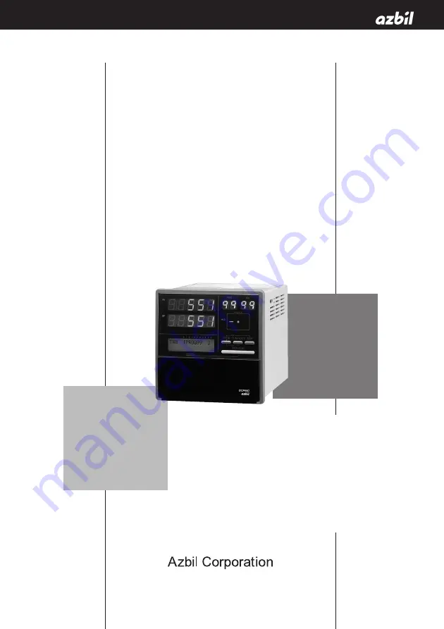
background image

DCP551 Mark 

ΙΙ

DIGITRONIK

Digital Control Programmer

User's Manual

No. CP-SP-1032E

Thank you for purchasing an Azbil
Corporation product.
This manual contains information for
ensuring the correct use of this
product.
It also provides necessary information
for installation, maintenance, and
troubleshooting.
This manual should be read by those
who design and maintain equipment
that uses this product. Be sure to
keep this manual nearby for handy
reference.

(Not for use in Japan)

Summary of Contents for dcp551 mark II

Page 1: ...t This manual contains information for ensuring the correct use of this product It also provides necessary information for installation maintenance and troubleshooting This manual should be read by those who design and maintain equipment that uses this product Be sure to keep this manual nearby for handy reference Not for use in Japan ...

Page 2: ... the product is used Copying or duplicating this user s manual in part or in whole is forbid den The information and specifications in this manual are subject to change without notice Considerable effort has been made to ensure that this manual is free from inaccuracies and omissions If you should find an error or omis sion please contact Azbil Corporation In no event is Azbil Corporation liable t...

Page 3: ... common mode voltages of all I O except for main supply are less than 33Vrms 46 7V peak and 70Vdc EQUIPMENT RATINGS Supply voltages 85 to 264V AC Frequency 50 60Hz Power or current ratings 40VA maximum EQUIPMENT CONDITIONS Do not operate the instrument in the presence of flammable liquids or vapors Operation of any electrical instrument in such an environment constitutes a safety hazard Temperatur...

Page 4: ...ent injury to the operator and others and to prevent damage to proper ty Be sure to observe these safety precautions Examples ii SAFETY PRECAUTIONS WARNING Warnings are indicated when mishandling this product might result in death or serious injury CAUTION Cautions are indicated when mishandling this product might result in minor injury to the user or only physical damage to the product Use cautio...

Page 5: ... 55 56 and 58 59 must meet the specified range Failure to heed this caution may lead to fire or equipment breakdown All terminal screws shall be tightened to specified torque Improperly tightened screws may lead to electric shock or fire Do not use unused terminals on the instrument as relay terminals for other equipment Failure to heed this caution may lead to electric shock fire or equipment bre...

Page 6: ...e inserted with the plus and minus poles correctly oriented Do not use damaged batteries or batteries that leak Do not throw batteries into a fire recharge disassemble or expose them to heat Store batteries in a cool dry place Failure to heed these cautions may result in burns or battery leakage Batteries should be kept out of reach of children since they may swallow them Should a child swallow a ...

Page 7: ...e DCP551 We strongly urge persons responsible for control design on the DCP551 read this chapter Chapter 6 OPERATION This chapter gives the selections of the basic display program selection operation and other information We strongly urge persons responsible for device design and operation on the DCP551 read this chapter Chapter 7 PARAMETER SETUP This chapter describes the parameter setting method...

Page 8: ...2 1 Structure 2 1 2 2 Console 2 2 Basic display status 2 2 Display 2 2 Key pad 2 4 Key chord functions 2 6 Loader jack 2 7 2 3 Input Type and Range Number 2 8 Input 2 8 Chapter 3 INSTALLATION AND MOUNTING 3 1 Before Installation 3 1 Mounting position 3 1 Sources of electrical interference and countermeasures 3 2 3 2 Installation 3 3 Panel cutout dimension 3 3 Installation procedures 3 4 Chapter 4 ...

Page 9: ...485 connection 4 13 RS 232C connection 4 16 Connection to ST221 4 17 4 12 Isolation During Input Output 4 18 Chapter 5 FUNCTIONS 5 1 Data 5 1 Data types 5 1 5 2 Program Pattern 5 2 Pattern 5 2 Events 5 5 PID group selection 5 16 Selection of output limiter group 5 16 G SOAK Guarantee soak 5 17 PV shift 5 18 Repeat 5 19 PV start 5 20 Cycle 5 21 Pattern link 5 22 Tag 5 23 5 3 Mode 5 24 Mode types 5 ...

Page 10: ...etup 7 1 Selecting parameter settings groups 7 1 Progression of individual items in parameter settings 7 1 Modifying individual items and exiting the setting mode 7 2 7 2 Parameter Setting List 7 4 Variable parameter setting 7 5 Detailed information on variable parameters 7 9 Event configuration data settings 7 12 Settings by event type 7 13 PID parameter setting 7 18 Setup data setting 7 21 Detai...

Page 11: ... 9 3 Procedures for saving single programs 9 3 Procedures for saving all programs 9 4 Procedures for saving setup data 9 4 Procedures for saving variable parameters 9 4 Procedures for saving PID parameters 9 5 Procedures for saving event configuration data 9 5 Procedures for saving all parameters 9 5 9 3 Load Procedures 9 6 Load menu 9 6 Card battery alarm panel 9 7 Procedures for loading individu...

Page 12: ...2 Alarm classification 10 2 Display behavior and alarm code upon input burnout 10 2 10 2 Key Input Related Problemst 10 3 Normal display mode problems 10 3 Parameter setting related problems 10 6 Program setting related problems 10 6 10 3 When the BAT LED Flashes 10 8 BAT LED flashes 10 8 Replacing the battery 10 8 Chapter 11 DISPOSAL Chapter 12 SPECIFICATIONS 12 1 Specifications 12 1 Attachment a...

Page 13: ...dicate corresponding parts in an explanation Indicates the result of an operation details displayed on the personal computer or other devices or the state of the device after operation DISP key key Indicate this product s keys These icons represent keys on the DCP551 s console FUNC PROG key Combinations of icons like this indicatate that PROG key must be pressed while holding FUNC key down PA01 C2...

Page 14: ......

Page 15: ...s Selection at setup allows the user to choose from among current proportional setting output current proportional output voltage time proportional output and open collector time proportional output Multi communications Selection at setup enables the user to switch between RS 485 and RS 232C on the rear panel terminal base At setup it is also possible to switch the communications port from the rea...

Page 16: ... PID parameter Setup Constant value control 99 pattern X 99 segment Event PID group output limiter group G SOAK PV shift Repeat PV start Cycle Pattern link Display selection Program No RUN HOLD RESET ADV FAST AUTO MANUAL AT Program setting Parameter setting Memory card operation FAST RAMP E AUTO MANUAL AT G SOAK reset Forward reverse operation Auto load PV1 PV2 selection RUN HOLD RESET ADV Program...

Page 17: ...ameters Five types of patterns are provided variable parameters event configuration data PID parameters setup data and constant value control data 1 3 Chapter 1 PRODUCT OUTLINE Program number 99 Segment count 8 SP Time Program number 3 Segment count 15 Time Program number 2 Segment count 19 SP Time Program number 1 Segment count 6 SP Time 1 2 3 4 5 6 18 19 13 14 15 2 3 4 5 6 7 8 Variable parameter...

Page 18: ...ersonal computer CPL Controller Peripheral Link Communications network is the host communications Chapter 1 PRODUCT OUTLINE PC PC PC RS 232C DCP551 slave station DCP551 slave station ST221DE05DCP Smart Terminal dedicated display slave station RS 485 DCP551 master station RS 232C RS 485 converter CMC10L001A000 RS 485 5 wire system RS 485 Connection example RS 485 3 wire system Communication control...

Page 19: ... D0 Y0 DCP551 Contents Digital programmable controller With memory card reader writer Without memory card reader writer PV input 1 channel PV input 2 channel Fixed 0 Not provided Auxiliary output 1 channel Auxiliary output 2 channel communication Not provided Inspection certificate provided Model number DCP551 0 Complying with the traceability certification ...

Page 20: ......

Page 21: ... Main unit Console and electric circuit board etc Terminal cover Covers power supply and prevents electric shock FUNC AT SETUP ENTER A M PID PARA CLR CARD LOAD SAVE LOADER CYC OUT DEV PV SP TM SYN RUN HLD MAN PRG AT BAT EG1 EG2 PROG RUN HOLD DISP RESET PROG SEG PROFILE MESSAGE MESSAGE ADV Lock screw Secures case to main unit Key cover Prevents operation errors Memory card slot A memory card is ins...

Page 22: ...s LED PV Lights during PV display otherwise off DEV Lights during deviation display otherwise off OUT Lights during output display otherwise off CYC Lights during cycle display otherwise off SP Lights during SP display otherwise off TM Lights during time display otherwise off SYN Off Chapter 2 NAMES AND FUNCTIONS OF PARTS Power on Parameter setting status Program setting status Program copy status...

Page 23: ...stant value control Indicates the alarm code AL when an alarm occurs in basic display status Segment number display Indicates a selected segment number in basic display status Indicates a set segment number in program setting status Off during constant value control Indicates an alarm code number when an alarm occurs in basic display status Mode display LED RUN HLD Indicates the RUN HOLD FAST END ...

Page 24: ...ETUP key Enter key ENTER key A M PID PARA CLR FUNC AT SETUP ENTER Denotes key term used in this manual CAUTION Do not use pointed objects such as mechanical pencils or pins to press the keys on the controller This may result in malfunction FUNC AT SETUP ENTER A M PID PARA CLR LOADER CYC OUT DEV PV SP TM SYN RUN HLD MAN PRG AT BAT EG1 EG2 PROG RUN HOLD DISP RESET PROG SEG PROFILE MESSAGE MESSAGE AD...

Page 25: ...s numerics during MANUAL operation When the MV or SV display flickers Changes program numbers or segment numbers When the program number or segment number flickers PARA Starts the variable parameter setting In basic display status FUNC PARA Starts the event configuration setting In basic display status PID Starts the PID parameter setting In basic display status SETUP Starts the setup setting In b...

Page 26: ...ication Program setting Program copy General reset Memory card operation available on the DCP551A model only Erases or resets a set value When a set value flickers Key operation FUNC CLR Cancels change in set value When a set value flickers DISP FUNC ENTER Inserts or delete a segment when a pattern SP setting is started FUNC PROG Changes RAMP X RAMP T or RAMP X RAMP E when a pattern SP setting is ...

Page 27: ...setting or return to a default value FUNC ENTER Segment insert remove RAMP selection key Press the ENTER key while holding down the FUNC key to go to the segment insert delete panel during SP and time setting in the program setting status Pressing the ENTER key while the FUNC key is held down during SP registration in the program setting status allows you to switch between RAMP X and RAMP T as wel...

Page 28: ...1 0 to 3400 0 1 FS N U13 0 0 to 1300 0 12 32 to 2372 0 1 FS PL II Y13 0 0 to 1300 0 13 32 to 2372 0 1 FS Z13 0 0 to 1300 0 14 32 to 2372 0 4 FS Gold iron chromel Z06 0 0 to 300 0K K Kelvin 15 Input type Symbol Code Accuracy under standard conditions 0 1 FS Input range FS Range No JIS 89Pt100 F50 200 0 to 500 0 64 300 0 to 900 0 0 1 FS F46 200 0 to 200 0 65 300 0 to 400 0 0 1 FS F32 100 0 to 150 0 ...

Page 29: ...2 NAMES AND FUNCTIONS OF PARTS Input type Symbol Code Accuracy under standard conditions 0 1 FS Input range FS Range No mA C01 4 to 20mA 48 Programmable range 19999 to 20000 Decimal point position is variable 0 1 FS Linear Z51 2 4 to 20mA 52 0 1 FS mV M01 0 to 10mV 49 0 1 FS L02 10 to 10mV 50 0 1 FS 0 to 100mV 51 0 1 FS mA C01 4 to 20mA 128 0 1 FS Linear Z51 2 4 to 20mA 134 0 1 FS V 0 to 1V 129 0 ...

Page 30: ......

Page 31: ...ng or wiring this module be sure to turn off the power to the module and all connected devices Doing so may result in an electric shock Do not disassemble the controller as this could lead to electric shock or malfunction CAUTION Be sure to follow the operating requirements regarding temperature humidity voltage vibration shock mounting direction atmosphere etc as stated in the specifications of t...

Page 32: ...ss communications equipment 9 Welding machines 10 High voltage ignition devices If the source of noise cannot be removed take the following measures Use a CR filter to suppress fast rising noise Recommended CR filter Model No 81446365 001 Use a varistor to suppress high amplitude interference Recommended varistors Model No 81446366 001 for 100V 81446367 001 for 200V Handling Precautions Varistors ...

Page 33: ... Handling Precautions Install the DCP551 in a location where the lower panel is not exposed to temperatures that exceed the operating temperature range 0 to 50 C Make sure that the temperatures above and below the controller meet specified requirements 3 3 Chapter 3 INSTALLATION AND MOUNTING 200 or more 450 or more 138 1 0 138 1 0 Unit mm ...

Page 34: ...autions When the provided mounting brackets are firmly secured and there is no looseness turn the screws only one full turn Over tightening the screws of the brackets can deform or damage the case The rear of the instrument must not be more than 10 above or below the horizontal plane Chapter 3 INSTALLATION AND MOUNTING Mounting 2 Mounting 1 Mounting bracket Mounting bracket ...

Page 35: ... equipment Failure to heed this caution may lead to electric shock fire or equipment breakdown Attaching the terminal covers after completing the controller connections is highly recommended Failure to heed this caution may lead to fire or malfunction Terminal covers are supplied with the controller If there is a risk of a power surge caused by lightning use a surge protector to prevent fire or de...

Page 36: ...sure the instrument s input impedance totals at least 1MΩ If less than 1MΩ the DCP551 may not be able to detect sensor disconnection Cautions when using data input devices in combination Input of the DCP551 input or output connected in parallel for input to an A D converter analog scanner etc may cause dispersion of the read data To prevent such occurrence take one of the following corrective meas...

Page 37: ...t the element to the terminals connect via shielded compensating lead wires NOTE For I O other than thermocouple use JCS4364 instrument cable or equivalent is commonly called twisted shielded cable for instrument use The following cable are recommended A shielded multicore microphone cord MVVS may be used if electromagnetic induction is comparatively low 4 3 Chapter 4 WIRING ...

Page 38: ...bject to noticeable vibration or impact be sure to use round crimp style solderless wire connectors to prevent lines from becoming disconnected from the terminals Be careful not to allow any of the crimp style solderless wire connectors to touch adjacent terminals or connectors The terminal screws shall be tightened to 0 78 to 0 98 N m torque 7 4 6 6 or less 7 3 or less Unit mm 3 7 Chapter 4 WIRIN...

Page 39: ...2 10 11 8 9 6 7 18 19 4 5 16 17 3 15 1 2 13 14 12 26 25 30 29 34 33 38 37 41 COM1 COM2 5 6 7 8 1 2 3 4 5 1 6 2 7 3 8 4 11 9 12 10 16 14 15 13 DO COM1 DO COM2 LOAD LOAD FG AUX2 AUX1 OUT2 OUT1 12 10 16 A B C 14 15 13 11 9 mV V RTD T C mA A B C mV V RTD T C O2 mA SDA SDB SD RDA RDB RD SG SG RS 485 RS 232C DI DI DO DO OUT AUX COMM OPTION PV CH1 PV CH2 MADE IN JAPAN 40733000100 Chapter 4 WIRING ...

Page 40: ...sert them in the same conduit or duct Grounding If grounding the shield wire or other lines proves difficult ground them separately to a grounding terminal block Ground resistance Less than 100Ω Conductor Annealed copper wire min 2mm2 AWG14 Max Length 20m Handling Precautions To ground the DCP551 connect the FG terminal terminal 52 or 53 to a single ground point without jumpering 3 1 E 2 4 Recomme...

Page 41: ...according to the type of sensor being used 4 7 T C Thermocouple input Resistance temperature detector input 54 55 56 RTD 54 55 56 A B C Chapter 4 WIRING CAUTION Current applied to current input terminals 55 56 and 58 59 must meet the specified range Failure to heed this caution may lead to fire or equipment breakdown 54 55 56 54 55 56 Current mA transmitter DC voltage input DC current input T C 57...

Page 42: ...Handling Precautions Be careful to connect the input polarities correctly Use shielded cable to connect the input 57 58 59 57 58 59 Current mA transmitter DC voltage input DC current input Chapter 4 WIRING ...

Page 43: ...collector outputs to malfunction There is no short circuit preventing circuit inside When connecting a semiconductor load such as a programmable controller sequencer select a module in which the current directions match Use one made inoperative by the leakage current produced when the digital outputs are shut off 4 9 43 Load 44 4 to 20mAdc Load resistance less than 600Ω Chapter 4 WIRING WARNING Be...

Page 44: ...onnection 48 49 4 to 20mAdc Load resistance less than 600Ω Receiver Chapter 4 WIRING 50 51 4 to 20mAdc Load resistance less than 600Ω Receiver WARNING Before removing mounting or wiring this module be sure to turn off the power to the module and all connected devices Doing so may result in an electric shock ...

Page 45: ...odule in which the current directions match Use one made inoperative by the leakage current produced when the digital outputs are shut off 4 11 5 6 7 8 17 18 19 20 9 EV1 EV2 EV3 EV4 EV5 EV6 EV7 EV8 External power supply 12 to 24Vdc Max load current Max common current Leakage current when OFF External power supply 12 to 24Vdc Max load current Max common current Leakage current when OFF 10 11 22 23 ...

Page 46: ...tc as no voltage contacts use one that maintains a potential of no more than 2V across the contacts when actuated and a leakage current of no more than 0 1mA when shut off The digital inputs remote switch inputs of all SDC40 and SDC10 series units can be connected in parallel If connecting them in parallel to another instrument carefully check the requirements of the other instrument before procee...

Page 47: ...terminating resistances a total of four when connecting a 5 wire system to the ends of the communications lines Use 1 2W or greater terminating resistances of 150Ω 5 If connecting three lines short circuit terminals 60 62 and 61 63 Do not short circuit the RDA to RDB and SDA to SDB terminals Doing so may cause the DCP551 to malfunction 4 13 60 SDB 61 62 63 64 RDA RDB SG SDA Chapter 4 WIRING ...

Page 48: ...e to connect SG terminals each other Failure to do so might cause unstable communications SDA SDB RDA RDB SG FG SDA Shield SDB RDA RDB SG Shield Shield Master station Terminating resistor Terminating resistor Terminating resistor Terminating resistor Slave station side DCP551 SDA SDB RDA RDB SG RDA RDB SDA SDB SG FG Slave station side DCP551 Slave station side DCP551 60 61 62 63 64 60 61 62 63 64 ...

Page 49: ...nly three RS 485 terminals are provided the areas designated with an asterisk are connected internally Handling Precautions Be sure to connect SG terminals each other Failure to do so might cause unstable communications SDA SDB RDA RDB SG SDA Shield SDB RDA RDB SG Shield Shield Master station Terminating resistor Terminating resistor Slave station side DCP551 SDA SDB RDA RDB SG RDA RDB SDA SDB SG ...

Page 50: ...t to point configuration There are three RD SD and SG communications terminals on the RS 232C interface on the master station which may not output data if not short circuited as shown above SD 61 63 64 RD SG 1 2 3 4 5 6 7 8 CD RD SD ER SG DR RS CS Host computer master station Example of connection Chapter 4 WIRING ...

Page 51: ...nating resistances of 150Ω 5 at each end of the communications lines The DCP551 operates as a master station when connected to an ST221 during communications Pin No 1 2 CD RD JIS code DCD RxD Name 3 SD TxD 4 ER DTR 5 SG GND 6 DR DSR 7 RS RTS 8 CS CTS Signal direction Host Instrument Chapter 4 WIRING 60 61 62 63 64 SG 3 4 1 2 5 ST221DE05DCP ...

Page 52: ...ed lines are not isolated Handling Precautions The terminal base is not isolated from internal digital circuits When not in use always replace the cap PV input CH1 PV input CH2 Digital circuit Control output Auxiliary output CH1 Loader communication External switch input Auxiliary output CH2 Communication Event output Memory card input available on the DCP551A model only Chapter 4 WIRING ...

Page 53: ...ink Cycle PV start Data changeable in RUN mode Event type data PID group and output limiter group control parameters Basic data only changeable in the READY mode Constant value control SP PID and other data SP and time SP and θ or SP and SP data Data for event 1 to 16 Data for PID group number used for control and output limiter group number Data indicating whether G SOAK is provided or not PV shi...

Page 54: ...t which is a straight line connecting the start point the SP set value in the previous segment and the end point the SP set value in the current segment Segments are classified as follows Rising RAMP or rising slope Previous segment SP setting current segment SP setting Falling RAMP or descending slope Previous segment SP setting current segment SP setting SOAK soaking Previous segment SP setting ...

Page 55: ...per and lower SP limiter range SP setting 1 to 10000 SPU The start point is the SP set value in the previous segment SP is a value resulting from adding a multiple of the external switch input count to the SP set value when the SP in the previous segment is the start point The segment ends when this SP reaches the SP setting in the current segment and the current segment SP is more than the previo...

Page 56: ...2 0 SPU hour 1 SPU min 2 SPU sec Select SP setting and SP setting decimal position using setup data setting C65 0 XXXXX 1 XXXX X 2 XXX XX 3 XX XXX 4 X XXXX External switch for pulse input requires 1 RAMP E using a setup data setting between C71 to C74 The pulse input interval time can be checked by setting event type 93 in the event Event type 93 is RAMP E time monitored during a period of 0 0 to ...

Page 57: ...ime events The On Time or both the On and Off Time can be set by event number and segment Output on off duration are as shown below NOTE The On Time is indicated by the length of the line from the start of the segment until the upturned arrow The Off Time is indicated by the length of the line from the start of the segment until the downturned arrow When the On Time is less than the off time the o...

Page 58: ...ff Time being set or set to more than 0 the output goes on when the On Time becomes 0 If the output was on at the end of the previous segment it stays on and does not go off momentarily between the two segments See segments 5 and 6 in the figure The G SOAK Time is not included in the On and Off Time See segment 7 Nor is the Wait Time included for a G SOAK that occupies an entire segment On time Of...

Page 59: ...t at the end of a segment or as the end state of the final segment See segment 10 in the figure Note however that an On Time or Off Time setting at the end of a RAMP T segment is either valid or invalid depending on the computational error On time Off time Output ON Output OFF 8 G SOAK wait Start of segment 8 The output goes on at the start of segment 8 when on is set to 0 Segment Chapter 5 FUNCTI...

Page 60: ...ue and H indicates the hysteresis value Outputs in READY mode are OFF But normal PV1 upper and lower limit operation and normal PV2 upper and lower limit operation events run also in the READY mode Event standby Standby events operate as described below If the event is in the gray area shown in the figure during a change from READY to RUN mode or when the power is restored after an outage the even...

Page 61: ...upper and lower limit operation events and PV1 PV2 differential of upper limit and lower limit events during automatic PV channel switching do not operate on models with only one PV input channel Normal PV1 upper and lower limit operation event and normal PV2 upper and lower limit operation events operate in the READY mode PV upper limit Normal PV1 upper limit operation Normal PV2 upper limit oper...

Page 62: ...PV1 PV2 differential lower limit H EV PV1 PV2 PV1 PV2 differential upper limit during automatic PV channel selection EV PV1 PV2 PV1 PV2 differential lower limit during automatic PV channel selection EV PV1 PV2 Note When the output goes on it stays on until READY mode Note When the output goes on it stays on until READY mode Chapter 5 FUNCTIONS ...

Page 63: ...lay Set event value is more than 0 using upper limit event Sampling cycle PV deviation rate upper limit event operation OFF ON up alarm OFF PV deviation rate lower limit event operation ON OFF ON 1 2 3 4 Sampling Time Set event value Set event value Set event value PV Chapter 5 FUNCTIONS Set event value is less than 0 using lower limit event Sampling cycle ON down alarm OFF ON OFF ON Time Set even...

Page 64: ...ntil the program reaches a segment with a new setting Note however that unless a setting is made in the first segment the program will assume that a set value of 0 is set in the first segment Segment Set value Code value 1 in event 3 Code value 2 in event 4 Code value 4 in event 5 Output code 1 2 5 4 3 Not set 3 Not set 6 0 OFF OFF OFF OFF OFF OFF ON ON ON ON ON OFF OFF ON OFF 0 OFF OFF OFF 0 0 0 ...

Page 65: ...the time event Segment Set value Code value 1 in event 3 Code value 2 in event 4 Code value 4 in event 5 Output code 1 2 5 4 3 Not set 5 3 Not set 6 0 OFF ON ON OFF OFF OFF ON OFF 0 OFF OFF OFF 0 0 0 5 1 3 OFF OFF OFF 0 0 0 0 3 0 OFF OFF OFF 0 0 0 Set time Not set 0 00 0 10 Not set 0 30 0 00 Time 0 10 0 30 OFF OFF OFF OFF OFF OFF OFF OFF OFF ON ON ON 3 2 6 4 Example Setting a timed code with 3 out...

Page 66: ...elay has to be entered for each channel Decimal 1 Binary code output 0 Off output 1 On output 0 0 0 0 0 0 1 2 0 0 0 0 0 1 0 3 0 0 0 0 0 1 1 4 0 0 0 0 1 0 0 5 0 0 0 0 1 0 1 6 0 0 0 0 1 1 0 7 0 0 0 0 1 1 1 8 0 0 0 1 0 0 0 9 0 0 0 1 0 0 1 10 0 0 0 1 0 1 0 11 0 0 0 1 0 1 1 12 0 0 0 1 1 0 0 13 0 0 0 1 1 0 1 14 0 0 0 1 1 1 0 15 0 0 0 1 1 1 1 16 0 0 1 0 0 0 0 17 0 0 1 0 0 0 1 Decimal 1 BCD code output 0 ...

Page 67: ...m PV1 selected PV2 selected Battery voltage drop The event goes on when the specified instrument state is reached and is off at other times Alarm Alarms are of two types PV range alarm group alarm code number 01 to 04 and instrument alarm group alarm code number 91 to 99 and battery voltage drop When the event type is all alarm the event goes on if one alarm occurs When the event type is a PV rang...

Page 68: ...stants that are used according to SP values are automatically selected to calculate control output The PID group number for each segment specifies A Seven PID groups from PID A1 to PID A7 can be used Selection of ouput limiter group Output limiter group number can be set for each segment to control the lower limit OL and upper limit OH of the control output oL and oH groups 1 to 9 can be used The ...

Page 69: ...d using setup data setting C71 to C74 1 G SOAK is cleared when an external switch contact is set to on or when PV meets the G SOAK clearing conditions 2 G SOAK is cleared when an external switch contact is set to on and PV meets the G SOAK clearing conditions G SOAK at start of segment PV and SP are compared at the beginning of the segment The segment starts when the absolute value of the differen...

Page 70: ...ait state continues until these conditions are met which is announced by the flashing of the linear LED at the left and the center of the profile display The operating condition is the same as HOLD at the continued time PV shift A PV correction value can be set for each segment PV is PV input value plus PV bias and PV shift Note however that in the READY mode and the constant value control mode PV...

Page 71: ...Handling Precautions When repeat operations involve multiple segments and the destination segment settings overlap nest or intersect the repeat operation will become an abnormal eternal loop Do not make such settings When the current segment does not contain a set value or the value is 0 executed values for program items for example set PV event values or set PID group selection values that are se...

Page 72: ...r that if there is no point where PV and SP are equal operation starts from the beginning of segment 1 When a PV start has been implemented the event operating point and the time event time are automatically corrected This is described in the figure shown below When PV is at 1 in the figure a rising PV start or a bi directional PV start starts from B and a falling PV start starts from C When PV is...

Page 73: ... is n 1 During cycle operation the operation at the last point in the final segment is not performed and executed values of program items sequels to settings in the previous segment for example PV event value pid group number that continue from a previous segment are cleared before program restart When the SP start point and end point are not equal SP changes in a step like manner during cycle ope...

Page 74: ...hat continue from a previous segment are cleared before program restart When a PV start has been programmed in a pattern at the destination link the PV start function operates after the link has been made PID computations are not initialized but continued after a link has been established When the READY mode is invoked at the end of an operation or in a RESET operation operation returns to program...

Page 75: ...an be entered in a program When segment 1 pattern item is set in a program setting a total of eight characters consisting of PROG plus two characters in the program number and __ two space characters Example Program no 1 PROG01__ Program no 19 PROG19__ Chapter 5 FUNCTIONS ...

Page 76: ... on values set in the segments are turned off Note however that DCP551 state dependent events still run Program numbers between 1 to 99 and set segment numbers can be selected during program operation All setup data some event configuration data and some constant value control data parameters can be changed in the READY mode Memory cards can also be used in the READY mode AUTO MANUAL Program opera...

Page 77: ...t be invoked END The END mode indicates the state of a program that has run its course When a program stops at the end MV output and events operate during PID control ON OFF control and other types of control During constant value control the END mode cannot be invoked READY FAST The READY FAST mode is a combination of the READY and FAST modes MV output SP output and events operate in the same way...

Page 78: ...ching between program operation and constant value control Constant value control data ConSt control mode item in the READY mode is used to switch between these two modes 0 Program operation 1 Constant value control NOTE Constant value control is available only when setup data setting C21 is set to more than 0 When C21 is set to 0 ConSt is also set to 0 END AUTO END MANUAL READY AUTO READY MANUAL ...

Page 79: ... FAST mode is invoked from the RUN HOLD READY and READY FAST modes During constant value control the FAST mode cannot be invoked AUTO Switches from the MANUAL mode to AUTO mode MANUAL Switches from the AUTO mode to MANUAL mode The basic display status changes as follows during this transition A controller function displays PV and output value The programmer function displays PV and SP Switching fr...

Page 80: ...d via communications may not go to the next segment but to the segment set in the communications message Operation RUN To RUN mode HOLD To RUN mode RESET To READY mode ADV To next segment FAST To FAST or READY FAST mode Original mode Program operation READY RUN HOLD FAST END READY FAST READY RUN Key Switch Commu nication Key Switch Commu nication Key Switch Commu nication Key Switch Commu nication...

Page 81: ...d by keys available in the basic display status Programmer PID control computations are not performed and 4 to 20mA output of scaled SP signals are output In the MANUAL mode SP levels can be controlled by keys available in the basic display status NOTE The constant value control mode cannot be invoked when the programmer function is used 5 29 Controlled process DCP551 Controller PV MV Chapter 5 FU...

Page 82: ...etector For thermocouple Setting setup data C07 C10 For DC current or voltage Setting setup data C08 C09 For DC current or voltage Setting setup data C04 to C06 For thermocouple or resistance temperature detector Setting setup data C02 C03 Setting setup data C30 Variable parameters PA51 to PA70 Setting variable parameter PA13 Setting program setting PV shift item Setting variable parameter PA12 Ch...

Page 83: ...ble parameter PA13 Setting program setting PV shift item Setting variable parameter PA12 PV PV1 Setting variable parameter PA111 Analog input 2 Cold junction compensation Wiring resistance compensation A D conversion Input range type Square root extraction Upper and lower limit alarm Temperature unit range Upper and lower limit value scaling Ratio Digital filter PV shift Bias Setting setup data C1...

Page 84: ...used The manipulated variable setting during this overrange is valid The normal channel is CH1 and the subchannel is CH2 Note however that when 7 is set in one of setup data C71 to C74 this situation is reversed when an external switch is turned on NOTE Switching type Setup data setting C25 0 Low temperature CH1 high temperature CH2 1 Low temperature CH2 high temperature CH1 2 CH1 setting 3 CH2 se...

Page 85: ...e lower limit of the dead band the channel switches from the high temperature to the low temperature sensor Example 2 1 When the temperature rises and the high temperature sensor senses that the temperature has risen to changeover point A the channel switches from the low temperature sensor to the high temperature sensor 2 When the high temperature sensor senses that the temperature has risen abov...

Page 86: ...hen the high temperature sensor senses that the temperature has risen to changeover point A the channel switches from the low temperature to the high temperature sensor 2 When the high temperature sensor senses that the temperature has risen above the upper limit of the dead band and reached point B the channel switches from the high temperature to the low temperature sensor at changeover point C ...

Page 87: ...ween point A the lower dead band limit and point B the higher dead band limit the controller calculates the value between the low temperature sensor and the high temperature sensor The ratio of the high temperature sensor varies between 0 at point A and 100 at point B 3 When the high temperature sensor senses that the temperature has risen above point B the higher dead band limit the channel switc...

Page 88: ...output performs a PID computation to prevent a major disturbance from occurring When a major disturbance occurs in the control output select automatic changeover C Select setup data setting C29 when an initial changeover setting is desired at power on during automatic changeover A and B When set to 0 the power stays off when set to 1 a switch is made to CH1 and when set to 2 a switch is made to CH...

Page 89: ... control computation Setting variable parameter PA16 PID parameter oL oH During ON OFF control AT computation Setting variable parameter PA08 PA09 PA10 AT executed Manipulated variable during overrange Setting setup data C33 C34 During overrange Manipulated variable in READY mode Setting setup data C32 In READY mode MANUAL Manipulated variable In MANUAL mode Preset MANUAL value Manipulated variabl...

Page 90: ... 5 respectively During AT executing Setting setup data C33 C34 During overrange Setting setup data C32 In READY mode In MANUAL mode Preset MANUAL value Output 1 time proportional output cycle Setting variable parameter PA15 Setup data C93 ON OFF control and AT execution are valid when setup data C21 is set to 2 or 4 respectively Setting setup data C35 C36 Output voltage 1 control During 6D output ...

Page 91: ...DY mode Setting setup data C32 In READY AUTO mode MANUAL SP In MANUAL mode Output 1 Current output 4 to 20mA Chapter 5 FUNCTIONS Auxiliary output 1 type Setting setup data C45 Upper and lower limit scaling Setting setup data C46 C47 4mA When the auxiliary output type is SP or deviation in the READY mode When the auxiliary output type is PV2 and a model with a PV input channel is used Auxiliary out...

Page 92: ......

Page 93: ...invoked READY HOLD END and READY FAST modes continue operating YES YES YES NO NO READY RUN HOLD FAST END and READY FAST modes continue operating Check start of general reset Parameters are reset to default values All programs are cleared Program run mode READY mode AUTO mode The program is reset to segment number 1 in program number 1 Segment advancing time 0 NO Program operation and fixed command...

Page 94: ...ram and segment number of the selected program in the READY program run mode Displays the program and segment number of the program and segment number of the currently running program in modes other than READY mode Both displays are off in the fixed command control mode Profile display Indicates when a program has been set in program run mode The display is off when no setting has been made When a...

Page 95: ...NUAL mode the number of digits available for SP recording flashes Display A2 Display A3 When the controller function is used in MANUAL mode the number of digits available for output values flashes OUT PV PROG SEG PROFILE Program number Segment number PV Output value Pattern trend DEV PROG SEG PROFILE Program number Segment number PV Deviation Pattern trend PV PV SP PROG SEG PROFILE Program number ...

Page 96: ...used in MANUAL mode the number of digits available for SP recording flashes Select Hours and Minutes Minutes and Seconds or 0 1 Seconds in the time unit setup data In the setup data also select Remaining Segment Time or Total Running Time SP TM PROG SEG PROFILE Program number Segment number SP Time Pattern trend CYC PV PROG SEG PROFILE Program number Segment number PV Remaining cycles Pattern tren...

Page 97: ...h Time display in hours and minutes Elapsed time Remaining time Displays events 1 to 8 from the left Displays events 9 to 16 from the left indicates that events are on and _ indicates that they are off The displays the 8 character tag PV CH1 value PV CH2 value indicates currently used channel In automatic switching C during intermediate CH1 and CH2 opera tion is displayed for both O U T D E V T I ...

Page 98: ...ays in the following order Display C1 display C2 display C3 display C1 Display C1 Display C2 Display C3 In MANUAL mode the number of digits available for output values flash OUT PV PROG SEG PROFILE PV Output value DEV PV PROG SEG PROFILE PV Deviation PV SP PROG SEG PROFILE PV SP Chapter 6 OPERATION ...

Page 99: ...is flashing to select a segment number When no program has been set only 1 can be selected When a program has been set any of the set segments can be selected The message panel displays the program tag when a program or segment number flashes The 8 character tag display is off when no program has been set Press the RUN key to start RUN mode operation from the displayed segment number when the prog...

Page 100: ... external switch is on a normal or reverse operation that is the reverse of setup data setting C23 is performed External switch number Function Detection way SW1 RUN Leading edge SW2 HOLD Leading edge SW3 RESET Leading edge SW4 ADV Leading edge SW5 Selects one of the following functions using setup settings SW6 RAMP E Leading edge SW7 FAST Leading edge SW8 Clears G SOAK using the OR condition Stat...

Page 101: ... OFF OFF ON ON OFF OFF ON ON OFF OFF OFF OFF OFF OFF ON ON ON ON OFF OFF OFF OFF OFF OFF OFF OFF OFF OFF ON ON 0 10 20 30 40 50 60 70 80 90 Status BCD system the one digit External switch number Weight SW9 1 SW10 2 SW11 4 SW12 8 Number selection OFF ON OFF ON OFF ON OFF ON OFF ON OFF OFF ON ON OFF OFF ON ON OFF OFF OFF OFF OFF OFF ON ON ON ON OFF OFF OFF OFF OFF OFF OFF OFF OFF OFF ON ON 0 1 2 3 4...

Page 102: ...system External switch number Weight SW9 1 SW10 2 SW11 4 SW12 8 SW13 16 OFF ON ON OFF ON ON OFF ON OFF OFF ON OFF OFF OFF ON ON OFF OFF ON OFF OFF OFF OFF OFF OFF OFF ON OFF OFF OFF OFF OFF OFF ON ON ON ON ON OFF ON OFF OFF OFF OFF OFF SW14 32 ON OFF ON ON OFF OFF ON ON ON SW15 64 OFF OFF OFF OFF ON ON ON ON ON Number selection 32 31 33 63 64 65 97 98 99 Chapter 6 OPERATION ...

Page 103: ... leading edge of the RUN signal to number selection hold 0 2 seconds or more 3 Time from RUN signal OFF to leading edge of RUN signal 0 2 seconds or more 4 Time from leading edge of RUN signal to RUN signal ON hold 0 2 seconds or more 5 Time from entry of selected number to program number change 0 4 seconds or less 6 Time from leading edge of RUN signal to start of RUN signal 0 4 seconds or less H...

Page 104: ...e setting registration there is no need to press the ENTER key Use the and keys to move the flashing digit Regardless of setup data C35 setting output changes going from AUTO to MANUAL modes are smooth Changes from MANUAL to AUTO program pattern SP are used and abrupt output changes may occur Auto tuning AT Set values can automatically be written when using auto tuning AT in the RUN HOLD FAST and ...

Page 105: ...using a variable parameter PA08 setting of 3 or 4 causes auto tuning to be performed on SP PID parameters tP A1 to tP A7 in order Auto tuning can be started by the AT key external switch input and by transmission The AT LED flashes during auto tuning Auto tuning terminates without writing PID constants and the AT LED goes off when any of the following conditions occur Operation is terminated by pr...

Page 106: ...t outputs are repeated several times and PV fluctuates When equipment failure may be caused by PID fluctuations set the PID value manually If just PID value can not be got in case of control object sets PID value with manual A variable parameter PA08 setting makes values set at the start of auto tuning valid A change in the PA08 setting made during auto tuning execution is ignored The new value is...

Page 107: ... Individual items are displayed in the vertical horizontal matrix shown on the following page with matrix sizes varying according to settings group The key key key and key are used to cycle through individual items The PARA key valid for variable parameters and event configuration data PID key valid for PID parameters and constant value control data or the SETUP key valid for setup data allow you ...

Page 108: ...rmal on state Pressing the DISP key enables the normal display mode Should display panel 2 show during display of an individual item or pressing the ENTER key not enable the registration state it means that settings cannot be made or modified for that item Handling Precautions When PA01 is set to more than 1 in a variable parameter setting PA03 and items beyond are not displayed PA03 and items bey...

Page 109: ...9 C10 C01 C100 Normal display mode DISP key Set value flashes Change set value ENTER key ENTER key Individual item Individual item key DISP key Use the PARA PID or SETUP keys as required by the specific settings group The ENTER key stores set values in memory The ENTER PID or SETUP keys do not store set values in memory key key key key key Chapter 7 PARAMETER SETUP ...

Page 110: ... is linear the PV1 linear decimal point position setup data setting C04 causes the decimal point position to change For example in a decimal point position of 1 19999 PVU PV1 becomes 19999 9 and 20000 PVU PV1 becomes 2000 0 PVU PV2 Like PVU PV1 a PV2 range type setup data setting C11 a PV2 decimal point position setup data setting C13 and a PV2 linear decimal point position setup data setting C14 ...

Page 111: ... 110 0 OUT 0 1sec 110 0 PA 15 Time proportional output cycle 15 1 to 240sec 10 PA 16 On off control differential 16 0 to 1000 SPU 50 SPU PA 17 PID computation initialize manipulated variable 17 5 0 to 105 0 Description is displayed and setting is not possible 0 0 PA 18 Unused 18 PA 19 Unused 19 PA 20 Unused 20 PA 21 Unused 21 PA 22 PV2 digital filter 22 0 0 to 120 0sec Description is displayed and...

Page 112: ...on A setting of 0 turns off the EG1 LED 0 PA 42 EG2 LED display event number 42 0 to 16 Description A setting of 0 turns off the EG2 LED 0 PA 43 PID computation initialize 43 0 No initialization during advance processing and PID group change 1 Initializes during advance processing but not during PID group change 2 No initialization during advance processing but initializes during PID group change ...

Page 113: ...compensation point No 8 0 PVU PA 66 66 PV1 equalizer compensation amount No 8 4000 PVU PA 67 67 PV1 equalizer compensation point No 9 0 PVU PA 68 68 PV1 equalizer compensation amount No 9 Range upper limit value PA 69 69 PV1 equalizer compensation point No 10 0 PVU PA 70 70 PV1 equalizer compensation amount No 10 Range lower limit value PA 71 71 PV2 equalizer compensation point No 1 0 PVU PA 72 72...

Page 114: ...on amount No 16 8000 PVU PA103 103 PV2 equalizer compensation point No 17 0 PVU PA104 104 PV2 equalizer compensation amount No 17 8500 PVU PA105 105 PV2 equalizer compensation point No 18 0 PVU PA106 106 PV2 equalizer compensation amount No 18 9000 PVU PA107 107 PV2 equalizer compensation point No 19 0 PVU PA108 108 PV2 equalizer compensation amount No 19 1 000 PA111 111 PV1 ratio Range upper limi...

Page 115: ...card load SAVE key memory card save The following keys are disabled when PA01 is set to 3 or to 2 Normal display mode PROG key program selection RUN HOLD key RUN operation HOLD operation PROG RUN HOLD keys RESET operation PROG DISP keys ADV operation FUNC keys FAST operation A M key AUTO operation MANUAL operation AT key AT start AT cancel Note however that in the normal display mode in MANUAL mod...

Page 116: ...e LOAD key can only be performed when PA05 is set to 0 A program autoload using the external switches can be performed when PA05 is set to 0 or 1 PA14 manipulated variable deviation rate limit When output deviation after a PID computation is larger than the set limit value the controller limits the output deviation both of the increase or decrease to the set value The following example shows the a...

Page 117: ... is shown in the diagram below PA41 EG1 LED display event number The console EG1 LED lights when an event number set in PA41 goes on and is off when it goes off Note however that the EG1 LED is off when PA41 is set to 0 PA42 EG2 LED display event number The console EG2 LED lights when an event number set in PA42 goes on and is off when it goes off Note however that the EG2 LED is off when PA42 is ...

Page 118: ...y setting 1 E07 2 21 Event 7 auxiliary setting 2 0 0 E08 t 22 Event 8 event type E08 1 23 Event 8 auxiliary setting 1 E08 2 24 Event 8 auxiliary setting 2 E09 1 26 Event 9 auxiliary setting 1 E09 t 25 Event 9 event type E09 2 27 Event 9 auxiliary setting 2 0 E10 t 28 Event 10 event type E10 1 29 Event 10 auxiliary setting 1 E10 2 30 Event 10 auxiliary setting 2 0 E11 t 31 Event 11 event type E11 1...

Page 119: ...ype Segment type PV type Event type 8 10 11 9 Meaning Message Absolute value deviation upper limit A DEV H Absolute value deviation rate upper limit with stanby A DEV H W Absolute value deviation lower limit with stanby A DEV L W Absolute value deviation lower limit A DEV L Range of auxiliary setting 1 Message Hysteresis 0 to 1000 SPU hysteresis Hysteresis 0 to 1000 SPU hysteresis Hysteresis 0 to ...

Page 120: ...19999 to 20000 SPU set point Operating point 19999 to 20000 SPU set point Operating point 19999 to 20000 SPU set point Setting category Operation category Instrument type PV type Instrument type PV type Instrument type PV type Instrument type PV type Event type 20 22 23 21 Meaning Message SOAK absolute value deviation lower limit S A DEV L SOAK absolute value deviation lower limit with stanby S A ...

Page 121: ...00 0sec sampling rate Hysteresis 0 to 1000 SPU hysteresis Hysteresis 0 0 to 100 0 hysteresis Hysteresis 0 to 1000 SPU hysteresis Range of auxiliary setting 2 Message Operating point 19999 to 20000 SPU set point Operating point 19999 to 20000 SPU set point Operating point 5 0 to 105 0 set point Operating point 19999 to 20000 SPU set point Setting category Operation category Instrument type PV type ...

Page 122: ...3 94 92 Meaning Message Segment number BCD code SEG BCD RAMP E time monitoring RAMP E TIME OUT Segment time SEG TIME Special segment SEG SEQUENCE Range of auxiliary setting 1 Message Number of output points 1 to 8 channels Operating point 0 0 to 3000 0sec 2 time out On Time 0 00 to 500 00 3 on time Segment specification 2 to 2 1 segment Range of auxiliary setting 2 Message Unused Unused Off Time 0...

Page 123: ...ype Mode type Instrument type Mode type Instrument type Mode type Instrument type Mode type Event type 138 140 141 139 Meaning Message Advance ADV PV range alarm PV ALARMS DCP551 alarm DCP ALARMS All alarm logical OR ALL ALARMS Range of auxiliary setting 1 Unused Unused Unused Unused Range of auxiliary setting 2 Message Unused Unused Unused Unused Setting category Operation category Instrument typ...

Page 124: ...vative time PID group 6 0 0 to 1000 0 ON OFF control when set to 0 0 0 to 3600sec No integral operation when set to 0 0 to 1200sec No derivative operation when set to 0 0 0 to 100 0 5 0 to manipulated variable upper limit Manipulated variable lower limit to 105 0 19999 to 20000 SPU 19999 to 20000 SPU Item code Item No User settings Settings and descriptions Factory default settings P l d rE oL oH ...

Page 125: ...p9 100 0 50 0 P A1 55 Proportional band PID group A1 0 I A1 56 Integral time PID group A1 0 d A1 57 Derivative time PID group A1 1000 SPU CP A1 59 Changeover point PID group A1 rE A1 58 Manual reset PID group A1 500 SPU tP A1 60 Tuning point PID group A1 100 0 P A2 61 Proportional band PID group A2 0 I A2 62 Integral time PID group A2 0 d A2 63 Derivative time PID group A2 50 0 rE A2 64 Manual res...

Page 126: ...0 0 rE A6 88 Manual reset PID group A6 6000 SPU CP A6 89 Changeover point PID group A6 5500 SPU tP A6 90 Tuning point PID group A6 100 0 P A7 91 Proportional band PID group A7 0 I A7 92 Integral time PID group A7 0 d A7 93 Derivative time PID group A7 50 0 rE A7 94 Manual reset PID group A7 20000 SPU fixed CP A7 95 Changeover point PID group A7 6500 SPU tP A7 96 Tuning point PID group A7 Item code...

Page 127: ...or t c and RTD display and setting is not possible 0 C 08 8 PV1 square root extraction 0 2 to 10 0 ratio depends on input range Description C01 settings for T C and RTD display and setting is not possible 0 2 C 09 9 PV1 square root extraction dropout 0 0 C 10 10 PV1 cold junction bias Item code Item No User settings Settings and descriptions Factory default settings 0 to 2 A setting of 0 means no ...

Page 128: ... display Ò Ó and setting cannot be performed 0 C 17 17 PV2 cold junction compensation 0 No 1 Yes Description C11 settings for T C and RTD display Ò Ó and setting cannot be performed 0 C 18 18 PV2 square root extraction 0 2 to 10 0 ratio depends on input range Description C11 settings for T C and RTD display Ò Ó and setting cannot be performed 0 2 C 19 19 PV2 square root extraction dropout 1 0 to 1...

Page 129: ...rtional Description is displayed and setting is not possible on model with one PV input channel When C25 is set to more than 1 is displayed and setting is not possible 0 C 26 26 PV channel switching system 19999 to 20000 PVU PV1 Description is displayed and setting is not possible on model with one PV input channel When C25 is set to more than 1 is displayed and setting is not possible When C26 is...

Page 130: ...en C21 is set to 0 the output is smooth regardless of setting 0 C 35 35 Manual change mode 5 0 to 105 0 0 0 C 36 36 Preset MANUAL value Description is displayed and setting is not possible C 37 37 Unused C 38 38 Unused C 39 39 Unused C 40 40 Unused C 41 41 Unused C 42 42 Unused 0 to 3600sec When set to 0 operation continues regardless of outage time Description The HOLD mode is invoked when the ou...

Page 131: ...nd lower limit of the range PV1 range upper limit C 67 67 SP limit upper limit Description is displayed and setting is not possible C 68 68 Unused C 69 69 Unused C 70 70 Unused 0 SP 1 PV 2 Deviation DEV 3 Manipulated variable MV 4 PV1 5 PV2 Description is displayed and setting is not possible on model without auxiliary output or with one auxiliary output 0 C 48 48 Auxiliary output 2 type 19999 to ...

Page 132: ... displayed and setting is not possible on model without communications 0 C 80 80 Communication method Description Can only be referenced for mechanical service use C 81 81 ROM ID C 82 82 ROM ITEM C 83 83 ROM revision C 85 85 CPU board ID C 86 86 I O board ID Description is displayed and setting is not possible C 87 87 Unused C 88 88 Unused C 89 89 Unused 1 C 90 90 PID type 0 Yes 1 No 0 C 91 91 PV1...

Page 133: ...are selected using C76 to C80 The communication address is used for settings 1 to 15 4800bps 8 bits even parity 1 stop bit 0 C 97 97 Communications port Description is displayed and setting is not possible C 99 99 Unused 0 to 255 Description A setting of 0 is normally used 0 C 98 98 Special function Description is displayed and setting is not possible C100 100 Unused Item code Item No User setting...

Page 134: ...input in the square root extraction is C09 or less than the dropout set in C19 an output of 0 can be obtained in the square root process Square root extraction is not performed when C08 and C18 are set to 0 C46 auxiliary output 1 lower limit C47 auxiliary output 1 upper limit C49 auxiliary output 2 lower limit C50 auxiliary output 2 upper limit This is the scaling setting of the auxiliary output T...

Page 135: ...de In G SOAK wait repeat cycle and pattern link time is displayed as integrated values When the time unit is hours min or min sec the display returns to 0 00 after 499 59 When the time unit is 0 1 sec the display returns to 0 0 after 2999 9 When the time unit is hour min a total operating time of 501 hours 30 minutes and 59 seconds is displayed as 1 30 In FAST mode a setting of 0 or 1 displays the...

Page 136: ...ge range input Check that the voltage between the terminals of the voltage pulse output is within the specified range This example shows the calculation for the connection of this unit and the PGM10N015 Note For connection with other model number check the specifications of each model Input current maximum Since the input current is 10mA or less up to two units 10mA X 2 20mA 24mA maximum allowable...

Page 137: ... below Description of symbols 1 Settings I0 set DCP551 output current range 2 to 22mA V0 end to end load voltage 13 2V VSSR actual voltage input to SSR VSSR rated input voltage range for SSR VSSR MIN to VSSR MAX VSSR MIN minimum SSR rated input voltage VSSR MAX maximum SSR rated input voltage Z internal SSR impedance VD internal SSR voltage drop normally about 1 to 2V 2 Equivalent circuit showing ...

Page 138: ... MAX Equation 4 VSSR I0 X Z VD 4 Equivalent circuit showing parallel connection of n SSRs Equations 5 and 6 below must be satisfied VSSR MIN I0 N X Z VD V0 Equation 5 VSSR VSSR MAX Equation 6 VSSR I0 N X Z VD I V 0 0 SSR 1 V Z V I N SSR n VSSR Z VD I N 0 DCP551 SSR D 0 I V 0 0 SSR 1 VSSR Z VD SSR n VSSR Z VD DCP551 Chapter 7 PARAMETER SETUP ...

Page 139: ...the DCP551 is 22mA Thus two PGMs can be connected in parallel When connected in series the maximum output current of the DCP551 is 22mA the allowable load resistance is 600Ω and the maximum voltage that can be applied to a load is 13 2V 22mA X 600Ω When 8 9mA is applied to a PGM the maximum voltage of the input terminals end to end is 3 7V 0 0089 X 260 X 1 05 1 3 3 7V Since 13 2 3 7 3 5 three PGMs...

Page 140: ...0 is displayed and setting is not possible 0 I 4 Integral time 0 to 1200 sec No integral operation when set to 0 Description When P is set to 0 0 is displayed and setting is not possible 0 d 5 Derivative time 0 0 to 100 0 Description When P is set to 0 0 is displayed and setting is not possible When I is not equal to 0 is displayed and setting is not possible 50 0 rE 6 Manual reset 5 0 to upper li...

Page 141: ...r starts flashing use the PROG key or the and keys to select a number Handling Precautions Program numbers cannot be selected during external switch input See Section 6 3 Selecting Programs page 6 7 for details Selecting program number during programming Press the FUNC and PROG keys in program setting state so that the program number starts to flash Use the and keys to make the desired changes and...

Page 142: ... items When programming is started the number of the started program and its segment are displayed State transition The figure below shows the transition of states during programming The numbered items 1 to 19 are described on the following page Normal display mode Program setting status Set point display status FUNC PROG key 1 DISP key 19 Program number or segment number flashes FUNC PROG key 16 ...

Page 143: ...EAr to delete the program beyond that segment Note however that the FUNC and CLR keys are invalid when a program is running 9 When the ENTER keys is used the program beyond the point where the key was pressed is deleted Pressing the DISP key does not delete any data but causes the display to show set values 10 Increase or decrease the values in the second setting and move the flashing digits 11 Co...

Page 144: ... setting 0 3 Use of controller function setup data C21 is set to something other than 0 4 These are settings used in each program and are shared by all segments Program item Pattern Event 1 Event 2 Event 3 Event 4 Event 5 Event 7 1 Event 7 2 PIG group output limiter group G SOAK PV shift Repeat PV start Cycle Pattern link Tag Segment number 1 No 1 setting 2 No 2 setting 1 SP 2 Time 1 Operating poi...

Page 145: ...ssing the ENTER key press the FUNC and ENTER keys to switch between RAMP types selecting RAMP X RAMP T or RAMP X RAMP E is made with setup data C61 5 Use the and keys to make the second setting time Setting range 0 00 to 500 00 0 0 to 3000 0 Time units are selected using setup data C62 to set Hour min Min sec 0 1 sec Since a colon cannot be displayed the decimal point is used instead 6 Press the E...

Page 146: ...ed in the top row and events 9 to 16 are displayed in the lower row The meaning of the codes used are listed below event off T time event P PV PV deviation rate event D Deviation absolute deviation M MV event S SP event C code time code event SP TM PROG SEG PROFILE Program number Segment number Set SP value Pattern trend Set time value RAMP type Event setting on off Chapter 8 PROGRAM SETUP ...

Page 147: ...nt operating point Setting range OFF 19999 to 20000 SPU OFF 0 to 20000 SPU for absolute value deviation events OFF 5 0 to 105 0 for MV events 4 Press the ENTER key to stop the flashing on display panel 1 Pressing the FUNC and CLR keys causes display panel 1 to return to unset state and the flashing stops Display PV events Unset values are indicated as NOTE A PV event setting consists of a setting ...

Page 148: ...ting 0 01 to 500 00 Off time setting 0 1 to 3000 0 6 Press the ENTER key to stop the flashing on display panel 2 Pressing the FUNC and CLR keys causes display panel 2 to return to unset state and the flashing stops Display time event Unset values are indicated as When the On Time is set to 500 00 or 3000 0 an Off Time cannot be set NOTE A time event setting consists of one setting an On Time or tw...

Page 149: ...auxiliary setting 1 4 Press the ENTER key to stop the flashing on display panel 1 Pressing the FUNC and CLR keys causes display panel 1 to return to unset state and the flashing stops Display code event Unset values are indicated as NOTE Code events use one subfunction A subfunction cannot be used when a setting has not been made Events that follow the event number of a code event number of output...

Page 150: ...e the second setting time Setting range 0 00 to 500 00 0 0 to 3000 0 Time units are selected using setup data C64 to set Hour min Min sec 0 1 sec Since a colon cannot be displayed the decimal point is used instead 6 Press the ENTER key to stop the flashing on display panel 2 Pressing the FUNC and CLR keys causes display panel 1 and 2 to return to unset state and the flashing stops Display Code eve...

Page 151: ...K wait at the end of a segment or an END mode at the end of a program an On Time or Off Time setting that is the same as the segment time is valid When the event is an event off Such event items on the programming map are skipped and not displayed When the event is an instrument event Such event items on the programming map are skipped and not displayed Chapter 8 PROGRAM SETUP ...

Page 152: ...ld 0 otL 0 and the flashing stops Display Unset values are indicated as Pld 0 otL 0 When setup data C21 is set to 0 and the programmer function is selected or when C58 is set to 1 PID groups output limiter group number items are skipped and not displayed NOTE When a PID group or output limiter group number is not 0 or both are something other than 0 they use a subfunction A subfunction cannot be u...

Page 153: ...flash Pressing the FUNC and CLR keys causes display panel 1 and 2 to return to unset state g S 0 and the flashing stops 5 Use the and keys to make the second setting G SOAK width Setting range 0 to 1000 SPU 6 Press the ENTER key to stop the flashing on display panel 2 Pressing the FUNC and CLR keys causes display panel 1 and 2 to return to unset state g S 0 and the flashing stops Display Unset val...

Page 154: ... FUNC and CLR keys causes display panel 1 to return to unset state and the flashing stops Display Unset values are indicated as When setup data C59 is set to 1 a PV shift item on the programming map is skipped and not displayed NOTE PV shift uses a subfunction A subfunction cannot be used when a setting has not been made Handling Precautions When PV shift is not set it is a sequel to a PV shift va...

Page 155: ...ses display panel 1 and 2 to return to unset state rP 0 and the flashing stops 5 Use the and keys to make the second setting repeat segment times Setting range 1 to 10000 6 Press the ENTER key to stop the flashing on display panel 2 Pressing the FUNC and CLR keys causes display panel 1 and 2 to return to unset state rP 0 and the flashing stops Display Unset values are indicated as rP 0 When setup ...

Page 156: ...V start 1 descending PV start 2 ascending PV start 3 bi directional PV start 4 Press the ENTER key to stop the flashing on display panel 2 Pressing the FUNC and CLR keys causes display panel 2 to return to unset state 0 and the flashing stops Display A PV start item is a program setting and is the same for each segment When setup data C60 is set to 1 a PV start item on the programming map is skipp...

Page 157: ... value Setting range 0 to 10000 4 Press the ENTER key to stop the flashing on display panel 2 Pressing the FUNC and CLR keys causes display panel 2 to return to unset state 0 and the flashing stops Display A cycle item is a program setting and is the same for each segment When setup data C60 is set to 1 a cycle item on the programming map is skipped and not displayed NOTE A cycle item setting does...

Page 158: ...tern link 1 to 99 program number at pattern link destination 4 Press the ENTER key to stop the flashing on display panel 2 Pressing the FUNC and CLR keys causes display panel 2 to return to unset state 0 and the flashing stops Display A pattern link item is a program setting and is the same for each segment When setup data C60 is set to 1 a pattern link item on the programming map is skipped and n...

Page 159: ...nd keys to make the first setting selecting the 8 characters for the tag The table below shows the 128 characters that can be used 4 Press the ENTER key and the cursor in the message panel disappears Pressing the FUNC and CLR keys causes the message panel return to displaying an 8 character tag consisting of PROG a two digit program number and two space characters The cursor is turned off Display ...

Page 160: ...ngs 3 Press the FUNC and CLR keys and you are prompted to confirm program deletion CLEAr flashes in display panel 1 4 Press the ENTER key to delete the program 5 The set value display state appears and is shown in both display panel 1 and 2 Display Segments that have not been set and unset values for SP and time are indicated by A program that is running in RUN HOLD FAST END or READY FAST mode can...

Page 161: ...letion dEL flashes in display panel 1 4 Pressing the ENTER key when InS is displayed in display panel 1 inserts the segment Pressing the ENTER key when dEL is displayed in display panel 1 deletes the segment 5 The set value display state appears Display segment insertion Display segment deletion When a segment is inserted a new segment is automatically created and the numbers of subsequent segment...

Page 162: ...een set the segment insertion indication InS is not displayed When 2000 segments have already been set pressing the ENTER key to execute an insertion cannot be used to insert a segment When segments are deleted the following segments are moved up and the numbers of subsequent segments are decremented by one When the final segment is deleted the displayed segment becomes an unset segment A program ...

Page 163: ...switch inputs See Section 6 3 Selecting Programs page 6 7 for details 3 Press the key and the PROG key to display COPY in display panel 1 The number of the program to be copied starts to flash in display panel 2 4 Press the and keys and currently unset program numbers that can be used as numbers for the program to be copied start to flash When there are no unset numbers is displayed in display pan...

Page 164: ...he ENTER key to execute the general reset and start startup operations that occur after a power up Press the DISP key cancels the general reset and returns the normal display mode Display In the constant value control mode program number segment number and profile display go off When the RAM backup fails at startup the controller automatically prompts you to confirm a general reset no key input is...

Page 165: ...del Memory card types The following memory cards can be used by the DCP551 Memory card functions Save write Saves selected DCP551 data on the memory card Load read Loads selected memory card data onto the DCP551 Model No Memory type Battery Capacity Byte No of programs SKM008A RAM Not replaceable 7 00K Max 20 SKM016A RAM Not replaceable 14 50K Max 52 SKM064A RAM Not replaceable 61 75K Max 99 SKM25...

Page 166: ...g single programs page 9 3 Saves all programs Save DCP Card All Programs ENTER key Procedures for saving all programs page 9 4 Saves setup data Save DCP Card SETUP Data ENTER key Procedures for saving setup data page 9 4 Saves variable parameters Save DCP Card PARA Data ENTER key Procedures for saving variable parameters page 9 4 Saves PID parameters Save DCP Card PID Data ENTER key Procedures for...

Page 167: ...e one program on the DCP to a memory card Program number selection Save Program 01 PROG01 File number selection ENTER key Save 01 PROG01 Card 01 File delete check ENTER key Save 01 PROG01 Card 01 Delete Save check ENTER key Delete Save 01 PROG01 Card 01 Save Save complete SAVE key Save 01 PROG01 Card 01 Good ENTER key Displays the tag to right side of the number key key Displayed when there are fi...

Page 168: ...51 setup data on a memory card Procedures for saving variable parameters This procedure saves the DCP551 variable parameter data on a memory card Data delete check Delete Old Data SAVE Save complete SAVE key PARA Data SAVE Good DISP key Normal mode display Save operation is not performed DISP key Normal mode display Displayed when there is data on the card Data delete check Delete Old Data SAVE Sa...

Page 169: ...formed Characters for saved parameters disappear as they are saved SET setup data PARA parameter PID PID parameters and constant value control data EV event configuration Displayed when there is data on the card Save complete All Parameters SAVE Good DISP key Normal display mode Data delete check Delete Old Data SAVE Save complete SAVE key EVENT Data SAVE Good DISP key Normal display mode Save ope...

Page 170: ...atteries are too low cause a card battery alarm panel to be displayed before the Load menu panel is displayed Normal display mode Load individual programs LOAD key ENTER key L o a d Card DCP Pro g ram Procedures for loading single programs page 9 7 Load all programs L o a d Card DCP All Programs ENTER key Procedures for loading all programs page 9 8 Load setup data L o a d Card DCP SETUP Data ENTE...

Page 171: ...key Procedures for loading individual programs This procedure loads single memory card files on the DCP551 File number selection Load Program 01 PROG01 Program number selection ENTER key Load 01 PROG01 DCP 01 Program delete check ENTER key Load 01 PROG01 DCP 01 Delete Load check ENTER key Delete Load 01 PROG01 DCP 01 LOAD Load complete LOAD key Load 01 PROG01 DCP 01 Good ENTER key Displays the tag...

Page 172: ...rs on the memory card onto the DCP551 Procedures for loading PID parameters This procedure loads PID parameters and constant value control data on the memory card onto the DCP551 Data delete check Delete Old Data LOAD Load completed LOAD key PID Data LOAD Good DISP key Normal display mode Load operation is not performed DISP key Normal display mode Data delete check Delete Old Data LOAD Load compl...

Page 173: ...be made when setup data variable parameters or all parameters saved on a DCP551 are loaded onto a DCP551 Mark II Setup data C21 C45 to C50 C52 C53 C80 C90 to C97 Variable parameters PA15 Setup data and all parameters stored on a DCP551 Mark II cannot be loaded onto a DCP551 A loading attempt generates card error 16 Data delete check Delete Old Data LOAD Load completed LOAD key All Parameters LOAD ...

Page 174: ...1 has been loaded onto the DCP551 program number 1 disappears File number 1 on a memory card is loaded onto the DCP551 as program number 1 When a load operation is successful the AUtO and LOAd indications go off and the normal display mode appears Unless the number of a program is selected using external switch inputs program 1 in segment 1 is selected If the load operation fails the AUtO and LOAd...

Page 175: ... 2 When program number 1 has been loaded onto the DCP551 program number 1 disappears File number 1 on a memory card is loaded onto the DCP551 as program number 1 When a load operation is successful the AUtO and LOAd indications go off and the normal display mode appears Unless the number of a program is selected using external switch inputs program 1 in segment 1 is selected If the load operation ...

Page 176: ...rd access sequence error Do over in file control 15 Card battery voltage drop warning Replace the card replace the card battery If replaceable 16 Wrong file version Create new file and create new data 17 Data or file are missing Create new file and create new data 18 DCP551 data full program load Delete unnecessary programs in the DCP551 19 DCP551 hardware error load error Do over 20 Card data inv...

Page 177: ... input signal due to disconnection or other cause lies outside the 10 0 to 110 0 range Alarm codes are displayed when errors are detected Self diagnostic routines performed continuously during operation PROM failures This routine is designed to detect errors in system programs stored in the PROM Not totally infallible there are cases where errors go undetected and result in measuring device operat...

Page 178: ...re than 110 FS Check PV1 AL02 PV1 underrange PV1 is less than 10 FS AL03 PV2 overrange PV2 is more than 110 FS Check PV2 AL04 PV2 underrange PV2 is less than 10 FS AL07 Oxygen sensor Oxygen sensor impedance Replace the oxygen sensor impedance error exceeded 130Ω AL90 Board configuration failure Incorrect board configuration Request the repair AL92 Adjustment value is abnormal Analog input output R...

Page 179: ...key once again Set to END mode Perform a reset operation press the PROG RUN and HOLD keys Invoke the READY mode and perform a RUN operation press the RUN HOLD key to go to the RUN mode Set to constant value control mode Set constant value control data ConSt to 0 Set to key lock Set variable parameter PA01 between 0 to 2 Cause Measure Select the set program Set to END mode Set READY mode to execute...

Page 180: ...to something other than 0 0 to switch from ON OFF control to PID control On off control is set with segment PID group number on off Set the segment PID group number between 1 to 9 or to A to switch to PID control Set to key lock Set variable parameter PA01 between 0 to 2 Cause Measure Set to program time unit as 0 1 sec Set 0 or 1 setup data C62 setting Set to END mode Perform a reset operation pr...

Page 181: ...e parameter PA01 to 0 Cause Measure Normal display mode not on Press DISP key to invoke normal display mode Set to constant value control mode Set constant value control data ConSt setting to 0 Set to key lock Set variable parameter PA01 between 0 to 2 Cause Measure Normal display mode not on Press DISP key to invoke normal display mode Mode other than READY Set READY mode to execute RESET operati...

Page 182: ...ect value for setup data C66 and C67 Cause Measure Not pattern item set Set SP and time data Cause Measure Set to memory protect Set variable parameter PA02 to 0 2 or 4 Cause Measure displayed in display panel 2 This item cannot be displayed or set To change setting connection item it may be able to change or set Data displayed in display panel 2 cannot be changed This item is display only Set to ...

Page 183: ...SET operation PROG RUN HOLD keys Cause Measure Set to memory protect Set variable parameter PA02 to 0 2 or 4 Program being set is running in RUN HOLD FAST END READY FAST Set READY mode to execute RESET operation PROG RUN HOLD keys Not set to pattern item on programming map Move to the pattern item on the programming map This segment is not set on the programming map Move to a set segment or set th...

Page 184: ...he user Phillips screwdriver New lithium battery model number 81446140 001 Chapter 10 MAINTENANCE AND TROUBLESHOOTING CAUTION Be sure to turn off the power supply when you are replacing the batteries Failure to heed this warning may lead to electric shock Be sure not to touch internal components during battery replacement or just after the power has been turned This may result in burn injuries Mak...

Page 185: ...he memory during battery replacement To charge this capacitor supply power to the DCP551 for about 10 minutes Replace the battery less than 24 hours after the power supply has been turned off When the BAT LED starts flashing replace the battery according to the following instructions 1 Leave the power on for about 10 minutes 2 Turn off the power 3 Open the console key cover and remove the lock scr...

Page 186: ...from the clip 10 Insert the new battery in the clip 11 Orient the positive pole of the battery forwards and press the clip with the battery into the square opening 12 Insert the connectors in the printed circuit board 13 Slide the controller back into the case 14 Open the key cover and firmly tighten the lock screw under the ENTER key using a Phillips screwdriver 15 When all procedures have been c...

Page 187: ...her temperatures When the BAT LED is flashing memory data is protected if the power is on When the data in memory is corrupted one of the following two conditions will occur 1 g rESt is displayed at power up and normal operation is not possible Press the ENTER key to perform a general reset and reset parameters to their factory default values and delete all program settings 2 Normal operation can ...

Page 188: ......

Page 189: ...emove the battery and dispose of both the product and the battery as industrial waste following local regulations Battery removal method See Replacing the battery in Chapter 10 MAINTENANCE AND TROUBLESHOOTING of this user s manual 11 1 EU ...

Page 190: ......

Page 191: ...tance Thermocouple DC voltage input Thermocouple 0 5µV Ω DC voltage lower than 1V range 0 5µV Ω DC voltage 5V range 3µV Ω DC voltage 10V range 6µV Ω Resistance temperature detector input Max 0 01 FS Ω within wire resistor 0 to 10W The ranges of F01 F33 P01 and P33 are Max 0 02 FS Ω Allowable wiring resistance Resistance temperature detector input The ranges except F01 F33 P01 and P33 are lower tha...

Page 192: ...arameter setting status On detection Min hold time 0 2s program number is 0 4s Input sampling cycle 0 1s Segment number display Digital 2 digits 7 segments green color Indicates a segment number on basic display status indicates a item number on parameter setting status Indicates an alarm code number when an alarm occurs Program number display Digital 2 digits 7 segments green color Indicates a pr...

Page 193: ... during program run No of PID groups 16 groups for program operation 9 segment specific and 7 automatic zone selecting Fixed command control mode READY Preparation state control stop RUN Run state AUTO Automatic run state MANUAL Manual run state output is operatable to console AUTO Automatic run state MANUAL Manual run state Enables manual output from system console Normal reverse operation select...

Page 194: ...CP551 provided with only slave node functionality 1 to 16 units max DIM 1 to 32 units max CMC SCM Data flow Half duplex Sync system Start stop sync Transmission system Balanced type differential Data line Bit serial Signal line Transmit and receive 5 lines 3 wires are connectable Communication speed 1200 2400 4800 9600 bps selectable Communication distance Max 500m sum total 300m in case of MA500 ...

Page 195: ...er composition 11 bits characters Data length 8 bits Isolation All inputs and outputs except external switch inputs are completely isolated Save SAVE Copies DCP551 data into a card Load LOAD Model No SKM008A SKM016A SKM064A SKM256C SKM008E SKM032E Memory type RAM RAM RAM RAM EEPROM EEPROM Capacity bytes 7 00K 14 50K 61 75K 251K 7 00K 29 75K No of programs Max 20 Max 52 Max 99 Max 99 Max 20 Max 99 ...

Page 196: ...rature range 20 to 70 C Terminal screw M3 5 self up screw Terminal screw tighten torque Mask and case material Mask Multiron Case Multiron Mounting Panel flush mount Mass Approx 1 5kg Standards compliance Mask and case color Musk Dark gray Munsell sign 5Y3 5 1 Case Light gray Ambient humidity range 10 to 90 RH without condensation Rated power supply voltage 105Vac Ambient humidity range 10 to 95 R...

Page 197: ...s Terminal cover 81446176 001 1 Auxiliary devices and others Optional Lithium battery set Memory card RAM battery not replaceable 81446140 001 SKM008A SKM016A SKM064A Memory card RAM battery replaceable SKM256C Memory card EEPROM no battery required SKM008E SKM032E DCP551 552 program work sheet CP SP 1002E Available on the DCP551A model only Chapter 12 SPECIFICATIONS ...

Page 198: ... 4 5 6 7 8 9 10 FUNC AT SETUP ENTER A M PID PARA CLR CARD LOAD SAVE LOADER CYC OUT DEV PV SP TM SYN RUN HLD MAN PRG AT BAT EG1 EG2 PROG RUN HOLD DISP RESET PROG SEG PROFILE MESSAGE MESSAGE 161 137 7 7 137 9 15 5 185 3 144 144 ADV Unit mm DCP551A console FUNC AT SETUP ENTER A M PID PARA CLR LOADER CYC OUT DEV PV SP TM SYN RUN HLD MAN PRG AT BAT EG1 EG2 PROG RUN HOLD DISP RESET PROG SEG PROFILE MESS...

Page 199: ...2 1 2 1 2 1 2 1 2 1 2 1 2 1 2 1 PID group 2 Output limiter group 1 Type 2 Count Shift value 1 Return segment 2 Count Type Count Link destination program 8 character tag Pattern Event 1 Event 2 Event 3 Event 4 Event 5 Event 6 Event 7 Event 8 Event 9 Event 10 Event 11 Event 12 Event 13 Event 14 Event 15 Event 16 PID group or Output limiter group G SOAK PV shift Repeat PV start Cycle Pattern link Tag...

Page 200: ......

Page 201: ...performed on PID groups A1 to A7 in READY mode 4 AT writing overshoot proof PID values to PID groups A1 to A7 in READY mode continuously performed 9 PA 09 Auto tuning MV lower limit 0 0 5 0 to upper limit 10 PA 10 Auto tuning MV higher limit 100 0 Lower limit to 105 11 PA 11 SP bias 0 SPU 10000 to 10000 SPU 12 PA 12 PV1 digital filter 0 0 0 0 to 120 0sec 13 PA 13 PV1 bias 0 PVU 1000 to 1000 PVU PV...

Page 202: ...000 PVU PV1 65 PA 65 PV1 equalizer compensation point No 8 3500 PVU 19999 to 20000 PVU PV1 66 PA 66 PV1 equalizer compensation amount No 8 0 PVU 1000 to 1000 PVU PV1 67 PA 67 PV1 equalizer compensation point No 9 4000 PVU 19999 to 20000 PVU PV1 68 PA 68 PV1 equalizer compensation amount No 9 0 PVU 1000 to 1000 PVU PV1 69 PA 69 PV1 equalizer compensation point No 10 Range lower PV1 range upper limi...

Page 203: ...4 0 PVU 1000 to 1000 PVU PV2 99 PA 99 PV2 equalizer compensation point No 15 7000 PVU 19999 to 20000 PVU PV2 100 PA100 PV2 equalizer compensation amount No 15 0 PVU 1000 to 1000 PVU PV2 101 PA101 PV2 equalizer compensation point No 16 7500 PVU 19999 to 20000 PVU PV2 102 PA102 PV2 equalizer compensation amount No 16 0 PVU 1000 to 1000 PVU PV2 103 PA103 PV2 equalizer compensation point No 17 8000 PV...

Page 204: ...t type 0 0 to 253 17 E06 1 Event 6 auxiliary setting 1 19999 to 20000 Setting range is variable according to the event types 18 E06 2 Event 6 auxiliary setting 2 19999 to 20000 Setting range is variable according to the event types 19 E07 t Event 7 event type 0 0 to 253 20 E07 1 Event 7 auxiliary setting 1 19999 to 20000 Setting range is variable according to the event types 21 E07 2 Event 7 auxil...

Page 205: ...iary 2 None 5 No Item code Item Factory default User Settings and descriptions settings settings 34 E12 t Event 12 event type 0 0 to 253 35 E12 1 Event 12 auxiliary setting 1 19999 to 20000 Setting range is variable according to the event types 36 E12 2 Event 12 auxiliary setting 2 19999 to 20000 Setting range is variable according to the event types 37 E13 t Event 13 event type 0 0 to 253 38 E13 ...

Page 206: ... absolute value deviation lower limit 86 SOAK absolute value deviation upper limit with standby 87 SOAK absolute value deviation lower limit with standby 88 Program No binary code Measuringinstrument Code Auxiliary 1 No of output Auxiliary 2 None 89 Segment No binary code 90 Program No BCD code 91 Segment No BCD code 92 Specified segment Measuringinstrument Mode Auxiliary 1 Segment specification A...

Page 207: ...38 Advance Measuringinstrument Mode Auxiliary 1 None Auxiliary 2 None 139 All alarms logical OR 140 PV range alarm 141 Instrument alarm 142 PV1 selection 143 PV2 selection 144 Battery voltage drop 145 to 253 Event off Auxiliary 1 None Auxiliary 2 None DCP551 Parameter Work Sheet ...

Page 208: ...t 18 oH 3 Manipulated variable upper limit Output limiter group 3 100 0 Manipulated variable lower limit to 105 0 19 P 4 Proportional band PID group 4 100 0 0 0 to 1000 0 0 0 On off control 20 I 4 Integral time PID group 4 0 0 to 3600sec 0 no integral operation 21 d 4 Derivative time PID group 4 0 0 to 1200sec 0 no derivative operation 22 rE 4 Manual reset PID group 4 50 0 0 0 to 100 0 23 oL 4 Man...

Page 209: ...eset PID group 9 50 0 0 0 to 100 0 53 oL 9 Manipulated variable lower limit Output limiter group 9 0 0 5 0 to manipulated variable upper limit 54 oH 9 Manipulated variable upper limit Output limiter group 9 100 0 Manipulated variable lower limit to 105 0 55 P A1 Proportional band PID group A1 100 0 0 0 to 1000 0 0 0 On off control 56 I A1 Integral time PID group A1 0 0 to 3600sec 0 no integral ope...

Page 210: ... group A5 50 0 0 0 to 100 0 83 CP A5 Switching point PID group A5 5000 SPU 19999 to 20000 SPU 84 tP A5 Tuning point PID group A5 4500 SPU 19999 to 20000 SPU 85 P A6 Proportional band PID group A6 100 0 0 0 to 1000 0 0 0 On off control 86 I A6 Integral time PID group A6 0 0 to 3600sec 0 no integral operation 87 d A6 Derivative time PID group A6 0 0 to 1200sec 0 no derivative operation 88 rE A6 Manu...

Page 211: ...16 PV2 linear range upper limit 10000 PVU 19999 to 20000 PVU PV2 17 C 17 PV2 cold junction compensation 0 0 Provided Compensated inside the instrument 1 Not provided Compensated outside the instrument 18 C 18 PV2 root extraction 0 0 Not provided 1 Provided 19 C 19 PV2 root extraction dropout 0 2 0 2 to 10 0 Ratio to input range 20 C 20 PV2 cold junction bias 0 0 1 0 to 1 0 C 21 C 21 Control output...

Page 212: ...al to 3 1999 9 to 2000 0 C45 set to 3 48 C 48 Auxiliary output 2 type 0 0 SP 1 PV 2 Deviation DEV 3 Manipulated variable MV 4 PV1 5 PV2 49 C 49 Auxiliary output 2 lower limit 4mA 0 SPU 19999 to 20000 SPU C48 not equal to 3 1999 9 to 2000 0 C48 set to 3 50 C 50 Auxiliary output 2 upper limit 20mA 10000 SPU 19999 to 20000 SPU C48 not equal to 3 1999 9 to 2000 0 C48 set to 3 52 C 52 SP output lower l...

Page 213: ...ps 2 2400bps 3 1200bps 78 C 78 Transmission code 0 0 8 bits even parity 1 stop bit 1 8 bits no parity 2 stop bits 79 C 79 Communication protocol 0 0 CPL 1 ST221 no PV trend 2 ST221 PV trend 80 C 80 Communication method 0 0 RS 485 1 RS 232C 81 C 81 ROM ID Description 82 C 82 ROM ITEM Can only be referenced for mechanical service use 83 C 83 ROM revision 84 C 84 Data version 85 C 85 CPU board ID 86 ...

Page 214: ... limit 3 P Proportional band 100 0 0 0 to 1000 0 0 0 On off control 4 I Integral time 0 0 to 3600sec 0 no integral operation 5 d Derivative time 0 0 to 1200sec 0 no derivative operation 6 rE Manual reset 50 0 0 0 to 100 0 7 oL Manipulated variable lower limit 0 0 5 0 to upper limit 8 oH Manipulated variable upper limit 100 0 Lower limit to 105 0 DCP551 Parameter Work Sheet Constant value control d...

Page 215: ...isplay panel 2 2 2 2 3 E EG1 LED 7 11 EG2 LED 7 11 END end 5 25 End of run 5 26 5 27 Error message list memory card 9 12 Event 5 5 8 7 Event configuration data 7 1 7 12 Event on delay 7 11 Event output open collector output connection 4 11 External dimensions 12 8 External switch input connection 4 12 External switch operation 6 8 F FAST fast 5 25 5 27 G G SOAK guarantee soak 5 17 8 13 General res...

Page 216: ...2 3 Program running 5 24 Program selection 6 7 6 9 Programmer 5 29 Programming map 8 4 PV deviation rate event 5 11 PV input analog input connection 4 7 PV shift 5 18 8 14 PV start 5 20 8 16 PV type event 5 8 R Range No 2 8 READY ready 5 24 READY FAST ready fast 5 25 Repeat 5 19 8 15 RESET reset 5 27 Resistance temperature detector 2 8 4 7 Root extraction 5 30 5 31 7 28 RS 232C 1 4 4 16 RS 485 1 4...

Page 217: ...cautions deleted 9 9 Set up data C91 C90 changed 10 9 Changed description of the 3rd item of Handling Precautions 11 5 CMA50 CMC10 changed 11 6 Weight Mass changed Oct 2001 6th Edition 1 5 Contents of D0 and Y0 changed 4 16 Handling Precautions deleted 6 4 Display A6 PV SP corrected Feb 2004 7th Edition RESTRICTIONS ON USE changed i Category II IEC664 1 IEC1010 1 IEC60364 4 443 IEC60664 1 changed ...

Page 218: ...s changed ii 3 1 4 1 4 8 Warning was changed 2 8 The thermocouple table was corrected 4 5 The label was changed 10 5 A descriotion was added 12 5 Power consumption was corrected 12 6 Standard compliance was corrected Dec 2013 16th Edition i Description of built in fuse was added 7 27 C99 and C100 were changed 7 33 7 34 C99 PV1 zener barrier adjustment and C100 PV2 zener barrier adjustment were del...

Page 219: ......

Page 220: ...1st edition June 1998 W 18th edition Feb 2016 F Specifications are subject to change without notice 09 1 12 2 Kawana Fujisawa Kanagawa 251 8522 Japan URL http www azbil com ...

Reviews: