

Note: Please read this instruction carefully for correct use of the product and preserve it for reference purposes.
All the examples and pictures used here are for reference only. There may be several technically incorrect places
or printing errors in this manual. The updates will be added into the new version of this manual. The contents of
this manual are subject to change without notice.This device should be operated only from the type of power
source indicatedon the marking label. The voltage of the power must be verified before using the same.
Network Video Recorder
Quick Start Guide
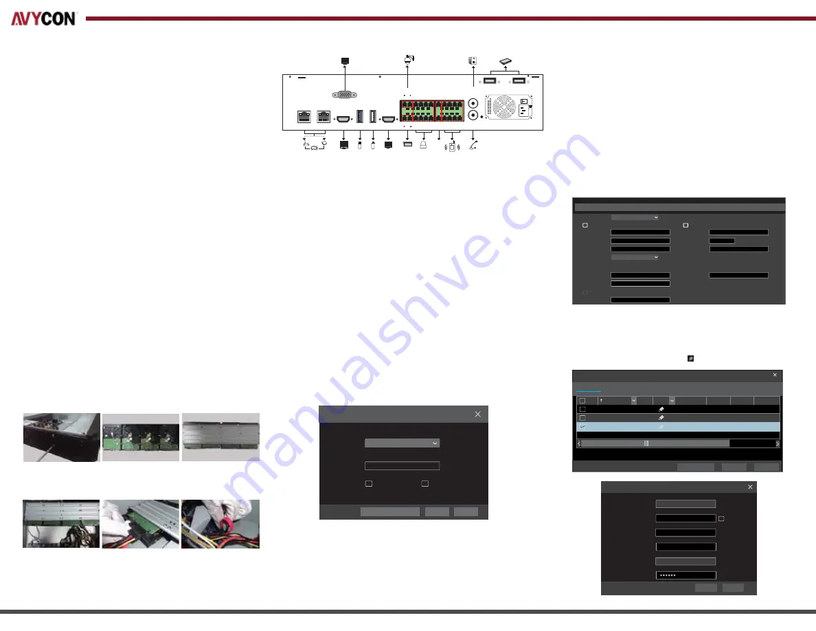
This series of the product supports 8 SATA hard drives.
The pictures of the installation are only for reference, please take the
real object as standard. Please make sure that the device is powered off
before installation
3. Install the mounting bar with HDDs back to the device.
4. Connect the power and data cables.
5. Install the upper four HDDs as the method mentioned above and
install back cover
Please check the device and the accessories after getting the device.
If there are any damages, shortages or defects, please contact your
dealer immediately.
For our HN500 series NVRs, the
default username is admin
and the
default password is 123456
. When starting HN500 series NVR for
the first time, you will see a prompt to begin a startup wizard. You can
skip this wizard if you would like, but it will help you configure basic
settings for your NVR. The wizard may allow you to also change the
default password for better security. If you decide to skip the wizard,
to access the live view and start using your NVR click on the Start
button in the bottom left of the menu bar on the bottom of the
screen and then click on Login and enter in the default password.
2. HDD Installation
1. Packing Check
3. Rear Panel Installation
The interfaces of the rear panel are for reference only.
• Startup
1. Connect the monitor and the power.
2. The device will boot and the power indicator will display blue.
3. A wizard window will pop up.
• Shutdown
Go to “Main Menu” and then select “Shutdown” icon. This will bring
up a shutdown window. The device will shut down by clicking “OK”
button. Then disconnect the power.
4. Startup & Shutdown
4. Login
Username
Password
admin
Login
Enter Password
Display Password
Log In Automatically
Login
Edit
S
ecurity
Q
uestion
Cancel
After you finish adding IP cameras, you can see the live images through
the monitor of the NVR. The following will mainly introduce how to add
the IP cameras via LAN/WAN. This NVR has two network ports, you can
select the network work pattern as required. Network fault tolerance
and multiple address setting are optional.
Network Fault Tolerance:
Bound two network ports to one IP address.
This pattern can increase the network bandwidth and form a network
redundant array to share the load. When one port goes wrong, the
otehr port will take over the entire load immediately and seamlessly.
Multiple Address Setting:
You shall set the IP address, subnet mask,
gateway and DNS of each ethernet port respectively.
The pictures are only for referenc, please refer to User anua for details
5.
Network Configuration
• LAN
1. Set the network of the NVR. Go to Start
→
Settings
→
Network
→
TCP/IP. Input IP address, subnet mask, gateway,
etc. If using DHCP, please enable DHCP in both the NVR and
the router.
2. Go to Start
→
Settings
→
Network
→
Port. Input HTTP port
(the default value is 80), server port (the default port is 6036).
3. Click “Apply” to save the settings.
4. Go to Start
→
Settings
→
Camera
→
Add Camera. The NVR
will automatically refresh the cameras searched. The IPC which
supports the Onvif protocol may be added manually. If the IPC
searched is not in the same local network as the NVR, you
should select the device and click to modify the IP address.
1.
Remove the cover and loosen the screws to take out two mounting bars.
2.
Get ready the HDDs installed and fix the HDDs on the mournting bar.
(For installing the HDDs well, please fix the round screw holes first)
Internet
12
LAN 2
LAN 1
AUDIO
IN
AUDIO
OUT
HDMI 2
HDMI 1
USB
USB3.0
VGA
e-SATA 1
e-SATA 2
8
1
3
5
7
2
4
6
G
N
D
N
O
1
N
O
2
N
O
3
N
O
4
G
N
D
C
O
M
1
C
O
M
2
C
O
M
3
C
O
M
4
Z Y
B A
P/Z
K/B
ALARM OUT
ALARM IN
RS 485
IP Address Settings
Obtain an IPv4 address automatically
Obtain
DNS
automatically
Obtain an IPv6 address automatically
Ethernet Port 1 ( Online )
Ethernet Port 2 ( Online )
Address
MCA Address
Address
MAC Address
192 . 168 . 1 . 2
10 .
151 . 151 . 1
0 . 0 . 0 . 0
. . .
0
192 . 168 . 1 . 1
Network Fault Tolerance
Ethernet Port 1
1500
Subnet Mask
Preferred DNS
Mask Length
Gateway
Primary Card
Work Pattern
(Modifying work pattern need to reboot )Gateway
Gateway
MTU
3.4.2
3.4.2
4.0.0.1.beta1
Version
80
80
80
No.
Address
Edit
Port
Protocol
Model
Subnet Mask
1
2
3
192.168.1.20
192.168.1.38
192.168.2.45
XXX
XXX
XXX
XXX
XXX
XXX
255
.
255
.
255
.
0
255
.
255
.
255
.
0
255 255 255 0
.
.
.
Quickly Add
Manually Add
Add Recorder
Add
Camera
Selected: 1/3
Add
Default Password
Remain Bandwidth: 108 / 120 Mb
Cancel
Mac Address
Address
Sync to IPC
Edit Camera
192
.
168
.
1
. 45
255
.
255
.
255
. 0
admin
192
.
168
.
1
. 1
Subnet Mask
Username
Gateway
Password
OK
Cancel
CE :98 :23 :75 :35 :22


