

Note: Please read this instruction carefully for correct use of the product and preserve it for reference purposes.
All the examples and pictures used here are for reference only. There may be several technically incorrect
places or printing errors in this manual. The updates will be added into the new version of this manual. The
contents of this manual are subject to change without notice.This device should be operated only from the
type of power source indicatedon the marking label. The voltage of the power must be verified before using
the same.
Network Video Recorder
Quick Start Guide
This series of the product supports 2 SATA hard drive. Please make
sure that the device is powered off before the installation. The pictures
of the installation are only for reference, please take the real object as
the standard.
The default username is
admin
and the default password is
123456
.
You must configure the wizard if you start the NVR for the first time
and you may change the password when you configure the wizard for
the first time. You can skip the settings of wizard next time. Click
“Start” and select “Login”. This will take you to see a login box. Input
default username and password you set and you can see the live
image.
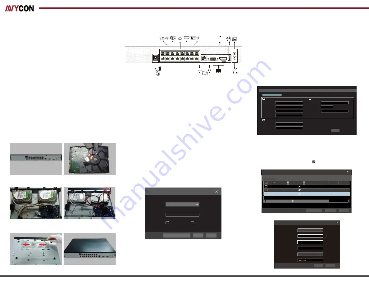
1. HDD Installation
2. Rear Panel Installation
1.
Loosen the screws to open the cover.
2. Screw the screws into the holes of HDD but
not tighten them.
3. Put the HDDs onto the bottom of the device.
5. Turn over the machine and secure the HDD
with the screws.
6. Install back the cover and secure it with the
screws.
Tips: Please check the inside structure of the device and make sure the cables connected well
before installing the cover back.
4. Connect the power and data cables.
The interfaces of the rear panel are for reference only.
• Startup
1. Connect the monitor and the power.
2. The device will boot and the power indicator will display blue.
3. A wizard window will pop up.
• Shutdown
Click “Start” and then select “Shutdown” icon. This will bring up a
shutdown window. The device will shut down by clicking “OK” button.
Then disconnect the power.
3. Startup & Shutdown
4. Login
Username
Password
admin
Login
Enter Password
Display Password
Log In Automatically
Login
Edit
S
ecurity
Q
uestion
Cancel
• LAN
1. Set the network of the NVR. Go to Start
→
Settings
→
Network
→
TCP/IP. Input IP address, subnet mask, gateway,
etc. If using DHCP, please enable DHCP in both the NVR and
the router.
2. Go to Start
→
Settings
→
Network
→
Port. Input HTTP port
(the default value is 80), server port (the default port is 6036).
3. The internal ethernet port is the port which connects all the PoE
ports with the NVR system. The PoE ports are available if the
internal ethernet port is online; if it is offline, all the PoE ports
will be unavailable. The IP address and subnet mask of the internal
ethernet port can be changed to make the port in the same
network segment with the IP cameras which directly connect to
the PoE ports of the NVR.
4. Go to Start
→
Settings
→
Camera
→
Add Camera. The NVR
will automatically refresh the cameras searched. The IPC which
supports the Onvif protocol may be added manually. If the IPC
searched is not in the same local network as the NVR, you
should select the device and click to modify the IP address.
2
4
6
8 10
12
14
16
AUDIO
OUT
DC48V
1
3
5
7PoE Ports9
11
13
15
LAN
VGA
AUDIO
USB IN
Internet
IP Address Settings
Ethernet Port 1 ( Online ) Internal Ethernet Port ( Online )
Obtain an IPv4 address automatically
Obtain an IPv6 address automatically
Address
192 . 168 . 1 . 2
Address
Subnet Mask
255 . 255 . 255 . 255
Mask Length
0
Gateway
192 . 168 . 1 . 1
Gateway
MTU
1500
Obtain
DNS
automatically
Preferred DNS
. . .
Alternate DNS
. . .
Apply
After you finish adding IP cameras, you can see the live images
through the monitor of the NVR. The following will mainly
introduce how to add the IP cameras via LAN/WAN.
5.
Network Configuration & Add IP Camera
CE :98 :23 :75 :35 :22
192
.
168
.
1 . 45
255
.
255
.
255 . 0
Edit Camera
Mac Address
Address
Sync to IPC
Subnet Mask
Gateway
192
.
168
.
1 . 1
Username
admin
Password
OK
Cancel
Add Camera
Quickly Add
Manually Add Add Recorder
2 192.168.1.38
80
255
.
255
.
255
.
0 XXX
XXX
3.4.2
3 192.168.2.45
80
255
.
255
.
255
.
0 XXX
XXX 4.0.0.1.beta1
No. Address
1 192.168.1.20
Port
Edit
Subnet Mask
Protocol
Model
Version
80
255
.
255
.
255
.
0
XXX
XXX
3.4.2
Selected: 1/3
Remain Bandwidth: 108 / 120 Mb
Default Password
Add
Cancel


