Classification: Avery Dennison - Public
Operators and Service Manual
Avery Dennison
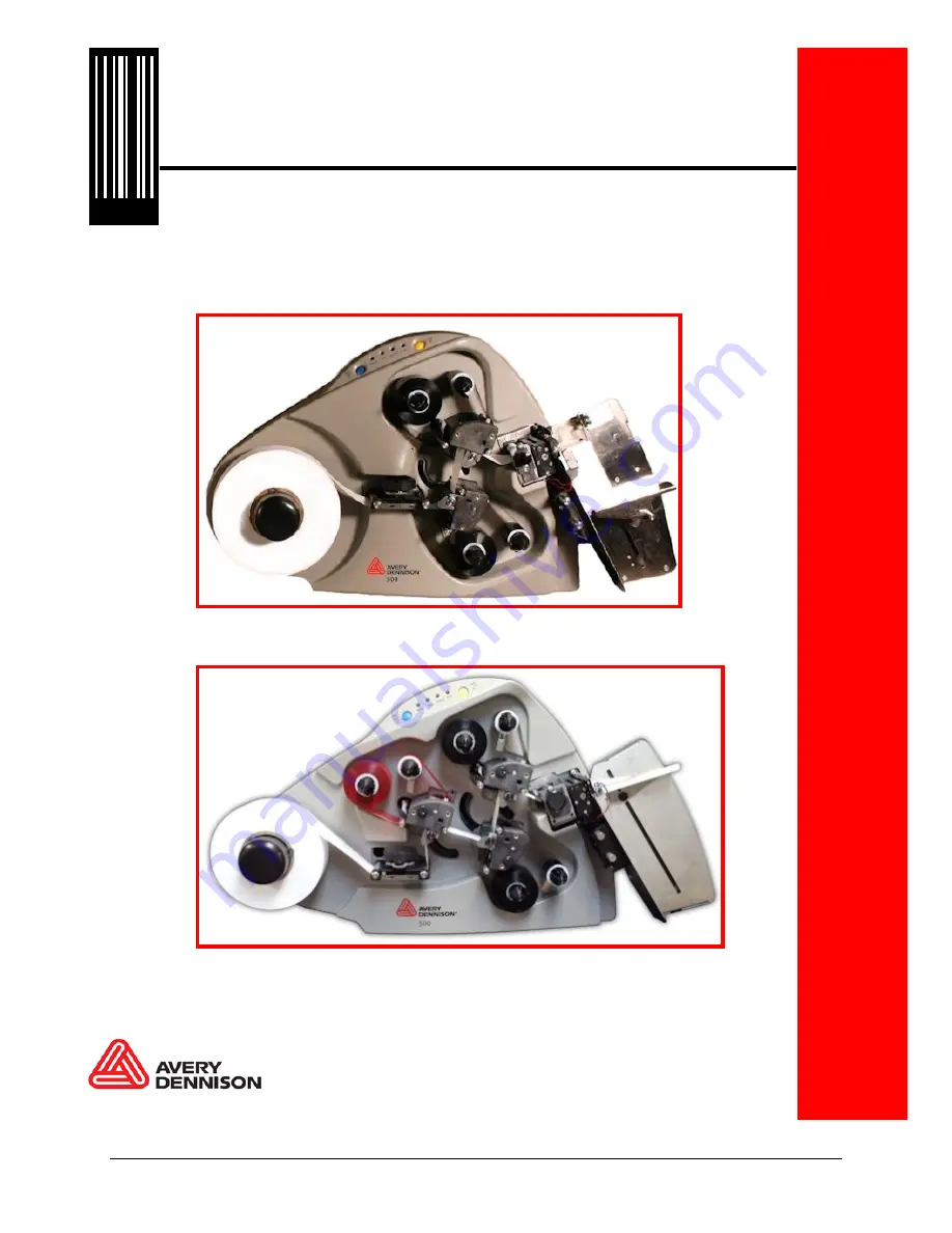
SNAP
TM
500 Thermal Printer, Gen 1 and Gen 2
300dpi: 2/1 2/0 1/1 1/0
600dpi: 1/1 2/1
Gen 1
– 2 heads
Gen 2
– 1, 2, or 3 heads
05631398 Rev 5.2 02/17
Original Instructions
© 2017 Avery Dennison Corp. All rights reserved
028028