WARNING:
To minimize the risk of potential safety problems, you should follow all applicable local and national
codes that regulate the installation and operation of your equipment. These codes vary from area to area and it is your
responsibility to determine which codes should be followed, and to verify that the equipment, installation, and operation
are in compliance with the latest revision of these codes.
Equipment damage or serious injury to personnel can result from the failure to follow all applicable codes and standards. We
do not guarantee the products described in this publication are suitable for your particular application, nor do we assume any
responsibility for your product design, installation, or operation.
If you have any questions concerning the installation or operation of this equipment, or if you need additional
information, please call us at 1-800-633-0405 or 770-844-4200.
This publication is based on information that was available at the time it was printed. At
Automationdirect.com
®
we
constantly strive to improve our products and services, so we reserve the right to make changes to the products and/or
publications at any time without notice and without obligation. This publication may also discuss features that may not
be available in certain revisions of the product.
®
3505 HUTCHINSON ROAD
CUMMING, GA 30040-5860
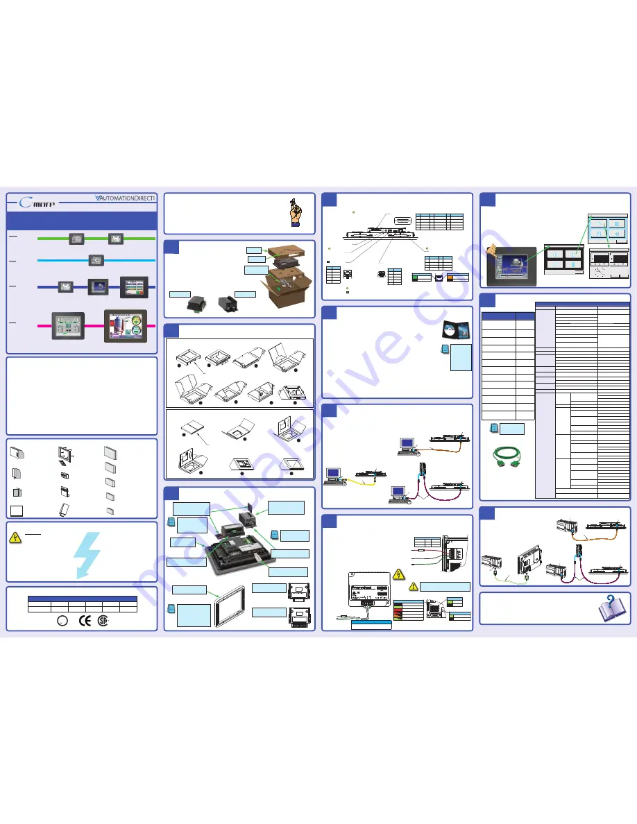
Minimum items required to create a working system:
•
C-more
Touch Panel - 6”, 8”, 10”, 12” or 15” model
•
C-more
Programming Software, p/n EA-PGMSW
•
C-more
USB Programming Cable, p/n USB-CBL-AB15 or Ethernet connectivity between PC and Touch Panel
• Power source:
C-more
AC/DC Power Adapter, p/n EA-AC or a dedicated 24 VDC (20.4 - 28.8 VDC) switching
power supply @ 1.5 A minimum
• Personal computer - to run the
C-more
programming software
• Communications Cable (serial or Ethernet) – to connect the
C-more
Touch Panel to your controller
•
Unpack the
C-more
Touch Panel from its shipping carton. Included in
the carton is the
C-more
Touch Panel, cutout template, mounting clips,
temporary support stand, DC power connector, gasket, and this Quick
Start Guide.
• Unpack any accessories that have been ordered, such as:
AC/DC Power Adapter, Expansion Assembly, CompactFlash memory,
programming cable, communications cable, etc.
• Inspect all equipment for completeness. If anything is missing or
damaged, immediately call the
AutomationDirect®
returns
department @ 1-800-633-0405.
Before you begin...
MAIN MENU
Information
Setting
Test Menu
Memory
E x i t
3
Unpack and Inspect
Install Optional Hardware Accessories (sold separately)
Assemble Temporary Support Stand
Connect Touch Panel to Computer
Accessing the Touch Panel Setup Screens
Additional Help and Support
• For product support, specifications, and installation troubleshooting, a Hardware User Manual can be
downloaded from the On-line Documentation area of the
AutomationDirect
Web site or
purchased through the
AutomationDirect
Sales team @ 1-800-633-0405 as part number EA-USER-M.
• For software programming help, refer to the
C-more
Programming Software on-line embedded help.
• Refer to demos of the product at: http://c-more.automationdirect.com/software/software_demo.html
• For additional technical support and questions, call our Technical Support team @ 1-800-633-0405 or
770-844-4200.
Data Sheet: EA-QSG, Rev. P
Copyright 2005-2014,
Automationdirect.com
Incorporated/All Rights Reserved Worldwide
• Access the Main Menu of the touch panel setup screens by pressing the extreme upper left
corner of the panel display area for three (3) seconds as shown below.
• Adjust the time and date for the panel by pressing the Setting button on the Main Menu,
then press the Adjust Clock button on the Setting screen.
• Use the right pointing arrows for the time or date display to select the unit to change. Use
the up and down arrows to increment or decrement the value for the selected unit.
• Press OK when done to accept the changes to the time and date that is retained in the
touch panel’s battery backed memory, or press Cancel to exit the Adjust Clock setup
screen without making any changes.
• Press the Main Menu button on the Setting screen and then the Exit button on the Main
Menu screen to return to the application screen.
2
5
6
Connect Touch Panel to PLC
Quick Start Guide
Quick Start Guide
Quick Start Guide
Quick Start Guide
Quick Start Guide
1
Purchased Cable
Description
Cable
Part Number
AutomationDirect CLICK,
Direct
LOGIC
PLC RJ-12 port, DL05, DL06, DL105,
DL205, D3-350, D4-450 & H2-WINPLC
(RS-232C)
EA-2CBL
Direct
LOGIC (VGA Style) 15-pin port
DL06, D2-250 (250-1), D2-260
(RS-232C)
EA-2CBL-1
Direct
LOGIC PLC RJ-11 port, D3-340
(RS-232C)
EA-3CBL
Direct
LOGIC DL405 PLC 15-pin D-sub
port, DL405 (RS-232C)
EA-4CBL-1
Direct
LOGIC PLC 25-pin D-sub port,
DL405, D3-350, DL305 DCU and
all DCM’s (RS-232C)
EA-4CBL-2
Allen-Bradley MicroLogix 1000, 1100,
1200, 1400, 1500 (RS-232C)
EA-MLOGIX-CBL
Allen-Bradley SLC 5-03/04/05,
ControlLogix, CompactLogix, FlexLogix,
DF1 port (RS-232C)
EA-SLC-232-CBL
Allen-Bradley PLC-5
DF1 port (RS-232C)
EAPLC5-232-CBL
Allen-Bradley MicroLogix, SLC
5-01/02/ 03, PLC5 DH485 port (RS-232C)
EA-DH485-CBL
GE 90/30, 90/70, Micro 90,
VersaMax Micro
15-pin D-sub port (RS-422A)
EA-90-30-CBL
MITSUBISHI FX Series 25-pin port
(RS-422A)
EA-MITSU-CBL
MITSUBISHI FX Series 8-pin mini-DIN
(RS-422A)
EA-MITSU-CBL-1
OMRON Host Link
C200 Adapter, C500
(RS-232C)
EA-OMRON-CBL
4
Available Communication Ports
For Future Use
Audio Line Out,
stereo, 1 Volt rms,
3.5mm Mini Jack
(Amplifier Required)
USB Port - Type B
Programming/Download
USB Port - Type A
USB Device Options
Ethernet 10/100 Base-T
PLC Communications,
Programming/Download
1 8
2
1
3 4
2 1
3
4
8 1
15 9
Pin
Signal
1 Frame
GND
TXD (232C)
RXD (232C)
Future
2
3
4
5 Logic
GND
Pin Signal
Pin Signal
6 LE
CTS (232C)
RTS (232C)
RXD+ (422/485)
7
8
9
10 RXD–
(422/485)
11 TXD+
(422/485)
TXD– (422/485)
Term. Resistor
do not use
12
13
14
15 do not use
Pin
Signal
1 TD+
TD–
RD+
do not use
2
3
4
Pin Signal
5
do not use
RD–
do not use
do not use
6
7
8
Pin
Signal
1
Vbus
D–
D+
GND
2
3
4
Pin
Signal
1 Vbus
D–
D+
GND
2
3
4
Shield
Shell
PLC Serial Communications
Network Activity LED (Orange)
On
Active Network Data
Network Idle
Off
Link Status LED (Green)
On Ethernet
Linked
No Ethernet Comm.
Off
Bottom View
Note: Device is not available on Base Feature touch panels, part numbers EA7-S6M-R and EA7-T6CL-R.
Compact Flash
memory slot #1
is located at the
top of panel.
Note: Use USB Programming Cable, p/n USB-CBL-AB15.
Shield
SHELL
6“ & 8” Touch Panel – Temporary Stand
1
2
3
4
5
6
7
8
Shipping Carton Packing Material
10”, 12“ & 15” Touch Panel – Temporary Stand
1
Shipping Carton Packing Material
2
3
5
6
4
Insert tabs
between layers
12
9
3
6
Adjust Clock
Cancel
OK
Time
Date
10 : 45 : 23
09 - 01 - 2005
AC/DC Power Adapter:
EA-AC
CompactFlash
Memory Card:
EA-CF-CARD
F
C
CF Card Interface Module:
EA-CF-IF
Expansion Assembly:
EA-EXP-OPT
6 inch Adapter Plate:
EA-6-ADPTR
(Used to retrofit new
C-more
6” touch panel
into existing EZTouch
non-slim panel cutout.)
Non glare 15 inch screen cover:
EA-15-COV2
(pk of 3)
D-SUB 15 pin 90 degree
Comm Port Adapter:
EA-ADPTR-4
D-SUB 15 pin to
Terminal Block Adapter:
EA-COMCON-3
Non glare 12 inch screen cover:
EA-12-COV2
(pk of 3)
Non glare 10 inch screen cover:
EA-10-COV2
(pk of 3)
Non glare 8 inch screen cover:
EA-8-COV2
(pk of 3)
Non glare 6 inch screen cover:
EA-6-COV2
(pk of 3)
USB Pen Drive,
2 GB:
SDCZ4-2048-A10
Touch Panel to PLC Communication Protocols & Cables
Safety Information
Accessories (sold separately)
General Description
The
C-more®
series of Touch Panels provides excellent capabilities and expanded features with their enhanced graphical
programming software, rugged hardware, and convenient accessories. Engineered into the product design to provide excel-
lent hardware and software are features such as those listed below. Some features are not available on the base feature panels.
• Analog touch screen (no touch cell boundaries)
• Plenty of memory and methods to get data in/out of the panel
• Overlapping active devices on the screen
• 65,536 colors for enhanced graphics
• Screen resolutions up to 1024 X 768 pixels
• Built-in project simulation, test on PC while developing
• Serial RS232, RS422/485 and Ethernet 10/100Base-T communications
• Programming via USB or Ethernet (Ethernet on full feature only.)
• Optional AC/DC Power Adapter (EA-AC)
• User replaceable bezels on 8”, 10”, 12” & 15” panels
• Animation of bitmaps and objects
• PID face plate, trending, alarming and a recipe database
• 4,000 built-in symbols, classic fonts: 6x8, 8x16, 8x32, 8x64, 16x16, 16x32, 16x64, 32x16, 32x32, 32x64, and Windows fonts
• Event Manager to trigger actions based on assigned state changes, schedules, PLC tag names, etc., setup in a database environment.
The event can also trigger a sound byte, initiate a screen capture, send a data file (FTP), send an E-mail, etc.
• Select unique background for each screen
• Trend Data logging
• Built-in FTP client/server, E-mail client, and Web server
• Internet Remote Access
• Audio output port, stereo – requires amplifier and speaker(s)
A table of complete specifications for all touch panels is located on the back of this Quick Start Guide. Touch
Panel and accessory dimension and mounting information is also located on the back. Please refer to the individual
data sheet inserts that are included with each accessory for additional details.
UL/CUL/CSA/CE Certification Numbers
Name
UL/CUL
UL508
CSA
CE
ISO-9000
C-more
Touch Panels &
Accessories
E157382
Per file #
E157382
234884
EN61131-2
✔
Agency Approvals
Setting
Adjust Clock
Adjust Display
Adjust Touch Panel
Beeper
Main Menu
C-more
to
Direct
LOGIC
VGA 15-pin port
serial cable
p/n EA-2CBL-1
DL-06 PLC
C-more
Touch Panel
Port 2
1
DL06 PLC
Stride™
Ethernet Switch
10/100 Base-T
(such as SE-SW5U)
H0-ECOM/H0-ECOM100
Ethernet Module
Ethernet CAT5
Cable - Straight-thru
C-more
Touch Panel
(Bottom View)
Ethernet
Port
Base Feature
STN and TFT
displays
Full Feature
STN displays
Full Feature
TFT displays
Full Feature
and very large
TFT displays
6” STN grayscale
EA7-S6M-R
6” TFT color
EA7-T6CL-R
6” grayscale
EA7-S6M
6” color
EA7-T6CL
8” color
EA7-T8C
10” color
EA7-T10C
12” color
EA7-T12C
15” color
EA7-T15C
Serial
Ethernet via
Hub or Switch
NOTE: EZTouch serial PLC
communication cables are
compatible with C-more
touch panels.
UL
C
US
R
8
NOTE: Refer to the individual
product data sheets that are
included with the accessories
for additional information.
NOTE: The C-more 6” touch panels
will fit into the existing cutout of
any EZTouch 6” slim bezel panel.
Use the C-more 6” Adapter Plate,
p/n EA-6-ADPTR, to install C-more
6” panels into existing cutouts of
EZTouch 6” non-slim (rounded
bezel) panels.
Expansion Assembly
EA-EXP-OPT
CF Card
Interface Module
EA-CF-IF
Compact Flash
Memory Card
EA-CF-CARD
AC/DC Power Adapter
EA-AC
6” Adapter Plate
EA-6-ADPTR
Shipping Carton Contents
AC/DC Power Adapter
EA-AC
Expansion Assembly
EA-EXP-OPT
Country of Origin
Date code
IOIOI – PLC
EA-ADPTR-4
KOYO ELECTRONICS INDUSTRIES CO., LTD.
Country of Origin
EA-COMCON-3
GND
SD–
SD+
RD–
RD+
TERM
Date code
KOYO ELECTRONICS INDUSTRIES CO., LTD.
Serial Port Adapter
EA-COMCON-3
Serial Port Adapter
EA-ADPTR-4
C-more
Touch Panel
Temporary
Support Stand
C-more
Touch Panel
USB Port – Type B
Programming/Download
USB Port –
Type A
PC
USB-CBL-AB15
USB
C-more
Touch Panel
(Bottom View)
Ethernet
Port
1
Ethernet CAT5
Cable - Straight-thru
Ethernet
Port
PC
Stride™
Ethernet Switch
10/100 Base-T
(such as SE-SW5U)
DL06 PLC
C-more
Touch Panel
(Bottom View)
Ethernet
Port
H0-ECOM/H0-ECOM100
Ethernet Module
Ethernet CAT5
Cable - Crossover
Ethernet via Crossover Cable
NOTE: CompactFlash memory
card designations – CF Slot #1
is at the top of the panel and
CF Slot #2 is the CF Card
Interface Module, p/n EA-CF-IF.
C-more
Touch Panel
(Bottom View)
Ethernet
Port
Ethernet CAT5
Cable - Crossover
Ethernet
Port
PC
• Connect a USB Programming Cable, p/n USB-CBL-AB15, from
a USB port type A on the PC to the USB type B programming
port on the
C-more
touch panel
•
or
connect the
C-more
touch panel and PC together
via an Ethernet hub or switch, and Ethernet cables (full
feature panels only)
•
or
use an Ethernet crossover cable directly between the
C-more
touch panel Ethernet port and the PC Ethernet port
(full feature panels only)
Ethernet via
Hub or Switch
Ethernet via
Crossover Cable
CF card plugs
into slot #1
at top of panel
CF card interface
module installs
in right slot only,
left slot for future
Cutout Template
located here.
EA-2CBL-1
USB Pen Drive
SDCZ4-2048-A10
10
Mounting Clips
and DC power connector
located in here.
Install the Software and Develop a Project
Following are the minimum system requirements for running
C-more
Programming Software,
p/n EA-PGMSW, on a PC:
• Personal Computer with a 333 MHz or higher processor (CPU) clock speed recommended; Intel® Pentium/
Celeron family, or AMD® K6/Athlon/Duron family, or compatible processor recommended
• Keyboard and Mouse or compatible pointing device
• Super VGA color video adapter and monitor with at least 800 x 600 pixels resolution
(1024 x 768 pixels recommended)
64K color minimum
• 300 MB free hard-disk space
• 128 MB free RAM (512 MB recommended); 512 MB free RAM (1 GB recommended) for Vista
• CD-ROM or DVD drive for installing software from the CD
• USB port or Ethernet 10/100 Mbps port for project transfer from software to touch panel (Ethernet port not
available on -R models)
• Operating System - Windows® XP Home / Professional Edition Service Pack 2 (32 bit), Windows 2000 with
Service Pack 4, Windows Vista® (32 or 64 bit) or Windows 7 (32 or 64 bit)
NOTE: To check your
computer system
information, go to
the Start Menu –
All Programs and
select Accessories,
then System Tools,
and finally System
Information.
Insert the supplied CD-ROM into the PC’s CD-ROM drive and follow the instructions. If you
need assistance during the software installation, please refer to the supplied Software Installation
Guide or call the
AutomationDirect
Technical Support team @ 770-844-4200.
7
100 - 240 VAC
50/60 Hz
AC Power Adapter
Not recommended for use with the EA7-T15C
when operating temperatures are expected
to be above 40 deg C.
Recommended AC Supply Fuse
3.0 A time delay, ADC p/n MDL3
Provide Power to the Touch Panel
PWR
CPU
TxD
RxD
BATT
IOlOl–PLC
Power LED (Green)
On
Power On
Power Off
Off
Serial TxD/RxD LED (Green)
On Comm. is active
No communication
Off
CPU Status LED (Green, Orange & Red)
Off
Power Off
Normal – CPU Run State
Green
Red
Memory Error
Operating System not found
Blinking
Red
Blinking
Orange
LCD Backlight Failure
Rear View
C-more
LED Status Indicators
Blinking
Green
Power Loss Detection
PWR
CPU
BATT
24 VDC, -15%, +20%
(20.4 - 28.8 VDC)
+
–
GND
Equipment
Ground
Recommended DC Supply Fuse
Panel Size
6“ – 10”
12“ & 15”
2.5 A
4.0 A
MDL2-5
MDL4
Rating
ADC p/n
EA-AC
DC Wiring
AC Wiring
• Wire a
dedicated
24 VDC (20.4 - 28.8 VDC) power source rated at a
minimum of 1.5 Amps to the DC connector on the rear of the
C-more
touch panel, include wiring the ground terminal to a
proper equipment ground. The recommended power supply is
AutomationDirect P/N: PS24-050D
•
or
install a
C-more
AC/DC Power Adapter, p/n EA-AC, to the rear
of the touch panel and wire an AC voltage source of 100-240 VAC,
50/60Hertz, to its AC connector
•
then
turn on the power source and check the LED status indicators
on the rear of the
C-more
touch panel for proper indication
9
Tightening Torque
Power supply cable torque
71 - 85 oz-in (0.5 - 0.6 Nm)
Mounting flange screw torque 57 - 71 oz-in (0.4 - 0.5 Nm)
PLC Compatibility Table
PLC Family
Model
Protocols
Allen-Bradley
MicroLogix 1000, 1100, 1200, 1400, 1500,
SLC 5-01/02/03, PLC5
DH485/AIC/AIC+
MicroLogix 1000, 1100, 1200, 1400, 1500
DF1 Half Duplex; DF1 Full Duplex
SLC 5-03/04/05
ControlLogix™, CompactLogix™, FlexLogix™
PLC-5
DF1 Full Duplex
ControlLogix, CompactLogix, FlexLogix - Tag Based
DF1 Half Duplex; DF1 Full Duplex
ControlLogix, CompactLogix, FlexLogix -
Generic I/O Messaging
EtherNet/IP Server
ControlLogix, CompactLogix, FlexLogix - Tag Based
EtherNet/IP Client
MicroLogix 1100, 1400, SLC 5/05,
both via native Ethernet port
MicroLogix 1000, 1100, 1200,1400, 1500,
SLC 5-03/04/05, all via ENI Adapter
Modbus TCP/IP
Modbus TCP/IP devices
Modbus TCP/IP
GE
90/30, 90/70, Micro 90, VersaMax Micro
SNPX
Mitsubishi
FX Series
FX Direct
Q02, Q02H, Q06H, Q12H, Q25H
Q CPU
Q, QnA Serial
QnA Serial
Q, Qna Ethernet
QnA Ethernet
Omron
C200 Adapter, C500
Host Link
CJ1/CS1 Serial; CJ1/CS1 Ethernet
FINS
Modicon
984 CPU, Quantum 113 CPU, AEG Modicon Micro
Series 110 CPU: 311-xx, 411-xx, 512-xx, 612-xx
Modbus RTU
Siemens
S7-200 CPU, RS-485 Serial
PPI
S7-200 CPU, S7-300 CPU; Ethernet
ISO over TCP
Productivity 3000
Productivity3000 Serial (P3-550)
AutomationDirect Prod. 3000 Serial
Productivity3000 Ethernet (P3-550)
AutomationDirect Prod. 3000 Ethernet
CLICK
all
AutomationDirect Modbus (CLICK)
AutomationDirect
Direct LOGIC
DL05/DL06
all
K-Sequence
Direct
NET
Modbus (Koyo addressing)
H0-ECOM/H0-ECOM100
Direct
LOGIC Ethernet
DL105
all
K-Sequence
DL205
D2-230
K-Sequence
D2-240
K-Sequence
Direct
NET
D2-250/D2-250-1/D2-260
K-Sequence
Direct
NET
Modbus (Koyo addressing)
D2-240/D2-250-1/D2-260
Using DCM
Direct
NET
Modbus (Koyo addressing)
H2-ECOM/H2-ECOM100
Direct
LOGIC Ethernet
DL305
D3-330/330P
(Requires the use of a Data
Communications Unit)
Direct
NET
D3-340
Direct
NET
D3-350
K-Sequence
Direct
NET
Modbus (Koyo addressing)
D3-350 DCM
Direct
NET
Modbus (Koyo addressing)
DL405
D4-430
K-Sequence
Direct
NET
D4-440
K-Sequence
Direct
NET
D4-450
K-Sequence
Direct
NET
Modbus (Koyo addressing)
All with DCM
Direct
NET
Modbus (Koyo addressing)
H4-ECOM/H4-ECOM100
Direct
LOGIC Ethernet
H2-WinPLC (Think & Do) Live V5.2 or later and
Studio any version
Think & Do Modbus RTU
(serial port)
H2-WinPLC (Think & Do) Live V5.5.1 or later and
Studio V7.2.1 or later
Think & Do Modbus TCP/IP
(Ethernet port)
W
ARNING
: The AC/DC Power Adapter should not be
used with the EA7-T15C touch panel when operating
temperatures are expected to exceed 40 °C [104 °F].
• Connect the serial communications cable between
the
C-more
touch panel and the PLC
•
or
connect the
C-more
touch panel and PLC together via
an Ethernet hub or switch, and Ethernet cables (full feature
panels only)
•
or
use an Ethernet crossover cable directly between the
C-more
Ethernet port and the PLC Ethernet port (full feature
panels only)