


Page 1
DURA
pulse
GS4 AC Drive Quick-Start Guide – 1st Ed, Rev.C 07/02/2021
DURA
pulse
GS4 AC Drive Quick-Start Guide
GS4_QSP_1edRevC 07/02/2021
GS4 AC Drives Installation Instructions
Sensorless Vector Control Variable Frequency Drive
• Please read this instruction sheet thoroughly before installation and keep this instruction sheet.
• To ensure the safety of operators and equipment, only qualified personnel familiar with AC drives should
install, wire, program, and operate the GS4 drive. Always read this instruction sheet thoroughly before using
the GS4 drive, especially the WARNING, DANGER and CAUTION notes. If you have any questions, please contact
AutomationDirect.
PLEASE READ PRIOR TO INSTALLATION FOR SAFETY
DANGER
• The ground terminal of the GS4 drive must be grounded correctly. The grounding method
must comply with the laws of the country where the GS4 drive is to be installed.
• After power has been turned off, the capacitors in the GS4 drive may retain a charge for
several minutes. To prevent personal injury, visually verify that the “CHARGE” LED has
turned off. Then measure to confirm that the DC bus voltage level between terminals (+1)
and (-) is less than 25VDC before touching any terminals. (Will take at least 5 minutes for
most GS4 models; 10 minutes for GS4 models ≥40hp.)
• The CMOS ICs on the internal circuit boards of the GS4 drive are sensitive to static electricity.
Please DO NOT touch the circuit boards with your bare hands before taking anti-static
measures. Never disassemble the internal components or circuits.
• If wiring changes must be made, turn off power to the GS4 drive before making those
changes. Allow the internal DC bus capacitors in the GS4 drive sufficient time to discharge
prior to making changes in power or control wiring. Failure to do so may result in short
circuit and fire. To ensure personal safety, allow DC bus voltage to discharge to a safe level
before making wiring changes to the GS4 drive.
• DO NOT install the GS4 drive in locations subject to high temperature, direct sunlight, or
flammable materials.
WARNING
• Never apply power to the output terminals U/T1, V/T2, W/T3 of the GS4 drive. If a fault
occurs during operation of the GS4 drive, refer to the fault code descriptions and corrective
actions to reset the fault before attempting to operate the GS4 drive.
• DO NOT use Hi-pot test for internal components. The semi-conductors in the GS4 drive are
easily damaged by high voltage.
CAUTION
• Long motor lead lengths may result in reflective wave due to impedance mismatch between
the motor cable and the motor. Reflective wave may damage the insulation of the motor.
To avoid the possibility of reflective wave damage, use an inverter-rated motor with an
insulation rating of 1600 volts. A load reactor installed between the GS4 drive and motor
will help to mitigate reflective wave.
• Nominal supply voltage to the GS4 drive should be less than or equal to 240 volts AC for
GS4-2xxx models, and less than or equal to 480 volts AC for GS4-4 models.
• Nominal supply current capacity should be less than or equal to 5kA RMS for GS4 models of
40hp or less, and less than or equal to 10kA RMS for GS4 models of 40hp and larger.
• The GS4 drive must be installed in a clean, well-ventilated and dry location, free from
corrosive gases or liquids.
• The GS4 drive must be stored within an ambient temperature range from –25°C to +75°C,
and relative humidity range of 0% to 90% without condensation.
• Do not apply AC power to the GS4 drive with the front cover removed. Following a fault of
the GS4 drive, wait 5 seconds before pressing the RESET key.
• To improve power factor, install a line reactor ahead of the GS4 drive. Do not install power
correction capacitors in the main AC supply circuit to the GS4 drive to prevent drive faults
due to over-current.
Minimum Wiring
• AC input power to L1, L2, L3 (for single-phase input, use two of the terminals) (For applicability of 1-phase input
power, please refer to Chapter 1 of the DURApulse GS4 AC Drives User Manual at
.)
• Ground from the power supply
• Drive power to the motor (U, V, W on T1, T2, T3) (For use with 3-phase motors only!)
• Ground to the motor
• STO1 and STO2 (both must be wired through appropriate N.C. safety-rated contacts to SCM1 and SCM2)
With this minimal wiring, the drive can be operated via the keypad to test the motor and drive installation.
See the “Parameter Quick-Start Set Up” (
) section to configure the drive for keypad operation.
Recommended Safety Wiring
We strongly recommend that customers use the STO safety feature.
The Safe Torque Off (STO) function turns off the power supplied to the motor through the hardware, so
that the motor cannot produce torque. This method of removing power from the motor is considered an
emergency stop, also known as “coast to stop.”
To use this feature, disconnect the appropriate factory-installed jumpers and wire a safety relay, safety PLC,
or E-Stop pushbutton as shown. See “GS4 with Sinking Digital Inputs” (
) for wiring using the GS4
internal power supply, or Appendix E of the GS4 user manual for wiring using an external power supply.
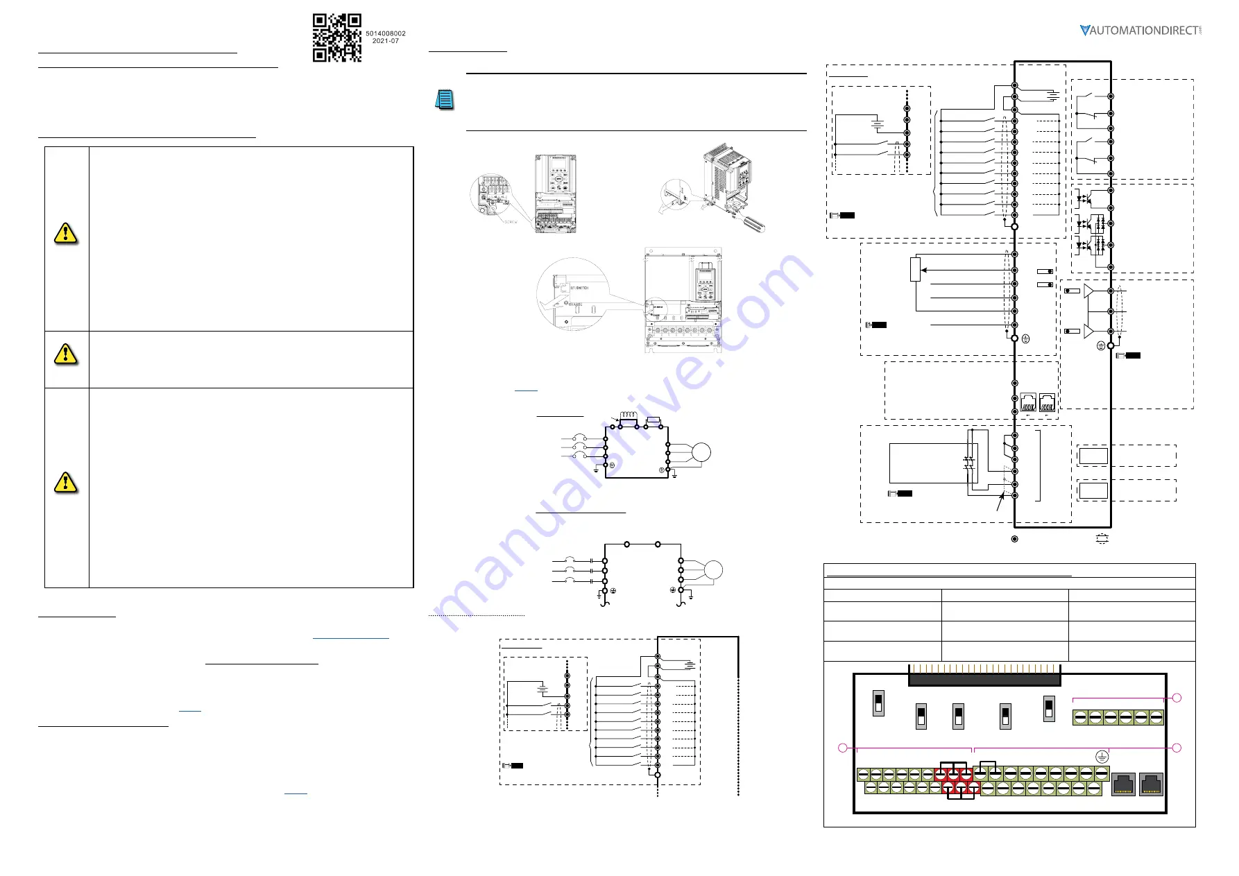
Wiring Diagrams
RFI Jumper Removal
If the power distribution system supplying the GS4 AC drive is a floating (IT) or an asymmetric
ground system, the RFI jumper must be removed.
Removing the RFI jumper uncouples the internal RFI capacitor (filter capacitor) between the GS4
drive frame and circuitry to avoid damaging those circuits and (according to IEC 61800-3) to reduce
ground leakage current.
GS4 Frame A through C
GS4 Frame D0 through G
Mains Wiring (Power Circuit)
For main (power) wiring terminal specifications, Please refer to “Specifications for Wiring Terminals –
Main-Circuit Terminals” (
GS4 Frame A through C
Brake resistor
(optional)
DC choke
(optional)
R(L1)
S(L2)
T(L3)
(L1)
(L2)
(L3)
U(T1)
V(T2)
W(T3)
+2
B1
B2
+1
-
Jumper
AC Motor
3 Ø
IM
Mains Wiring Diagram
for frames A thru C
3-phase power is provided
For connection of Dynamic Braking Units and separate control power (large-frame drives only).
GS4 Frames D and Larger
Control-Circuit Wiring
GS4 with Sourcing Digital Inputs
SOURCING
Mode (field devices are sinking)
FWD/STOP* **
REV/STOP* **
Multi-step 1*
Multi-step 2*
Multi-step 3*
Multi-step 4*
N/A*
N/A*
N/A*
N/A*
+
DCM
+24V
FWD
DIC
REV
DI1
DI2
DI3
DI4
DI5
DI6
DI7
DI8
Factory Settings
Internal
Power
Supply
NOTE
* Do NOT apply mains voltage directly to above terminals.
** If P4.09 = 1, FWD/REV direction is controlled by analog input only.
+
FWD/STOP* **
REV/STOP* **
Multi-step 1*
DCM
+24V
FWD
DIC
REV
Wiring if using
an external
power supply
+24V
The rest of the control wiring is the same as for SINKING mode.
Internal P.S. = 200mA max
GS4 with Sinking Digital Inputs
Control terminals
Shielded leads & Cable
SINKING
Mode (field devices are sourcing)
Communication
extension card
Option
Slot 1
5kΩ
3
2
1
Option
Slot 3
8 1 8 1
Pin 1~2, 7, 8: open or no connection
Pin 3, 6:GND
Pin 4:SG-
Pin 5:SG+
FWD/STOP* **
REV/STOP* **
Multi-step 1*
Multi-step 2*
Multi-step 3*
Multi-step 4*
N/A*
Multi-Function Output Terminals
I/O & RELAY
extension card
N/A*
N/A*
N/A*
+
AO1
SGND
SG+
SG-
DO1
DO2
DOC
FO
DCM
DCM
R1O
R2O
R2C
R2
+24V
FWD
DIC
REV
DI1
DI2
DI3
DI4
DI5
DI6
DI7
DI8
AO2
R1
R1C
+10V
-10V
AI1*
AI2*
AI3
ACM
ACM
Factory Settings
RJ
45-1
RJ
45-2
Analog Signal Common
Analog Output 2 Terminal
0~10VDC / 4~20mA
Analog Output 1 Terminal
0~10VDC / -10~+10V
0~10V / 0~20mA / 4~20mA
0~10V / -10 to +10V
+10V / 20mA
-10V / 20mA
Analog Signal Common
Modbus RS-485
BACnet
Internal
Power
Supply
NOTE
* Do NOT apply mains voltage directly to above terminals.
** If P4.09 = 1, FWD/REV direction is controlled by analog input only.
SW3*
SW4*
* Ensure that the physical switches for AI1 and AI2
(located above the control terminal blocks) are
set for the correct voltage/current configuration.
NOTE
SW1*
SW2*
SCM1
STO1
+24V
STO2
ECM
Safety Relay,
Safety PLC,
or
E-Stop PB
(2 NC contacts required)
SCM2
NOHC
NOHC
Red
STO
Terminals
*
* Remove factory-installed short-circuit
jumper from +24V–STO1–STO2 when
using STO function with in24VDC.
NOTE
See User Manual Appendix E
for STO details.
* Ensure that the physical
switches for AO1 and AO2
(located above the control
terminal blocks) are set for
the correct voltage/current
configuration.
NOTE
0~10V / 0~20mA / 4~20mA
Resistive Load:
250VAC / 3A (N.O.)
250VAC / 3A (N.C.)
Inductive Load:
250VAC / 1.2A (N.O.)
250VAC / 1.2A (N.C.)
Estimate at COS (0.4)
Resistive Load:
30VDC / 5A (N.O.)
30VDC / 3A (N.C.)
+
FWD/STOP* **
REV/STOP* **
Multi-step 1*
DCM
+24V
FWD
DIC
REV
Wiring if using
an external
power supply
Internal P.S. = 200mA max
Digital Output terminals
5~48 VDC / 50mA
Digital Output terminals
5~48 VDC / 50mA
Multi-Function Output
Frequency terminals
5~30VDC / 30mA 100kHz
Digital Output common
Specifications for Wiring Terminals – Control Circuit
GS4-xxxx All Models; All Frame Sizes
Terminal
Wire Gauge
Torque
A
24–16 AWG
[0.20–1.31 mm
2
]
5kg·cm
[4.3 lb·in]
B
26–16 AWG
[0.13–1.31 mm
2
]
8kg·cm
[6.9 lb·in]
C
24–16 AWG
[0.20–1.31 mm
2
]
2kg·cm
[1.7 lb·in]
FWD DI1 DI3 DI5 DI7 SGND
DCM REV DI2 DI4 DI6 DI8 SG+ SG-
0~10V
-10~10V
SW1
SW2
RJ45-1 RJ45-2
SW3
SW4
SW5
0~10V
0/4~20mA
AO2
AO1
0~10V
0/4~20mA
AI1
0/4~20mA
0~10V
AI2
Open
120Ω
485
Control circuit board is removable from the GS4 (for ease of wiring)
R2
R1O
R1C
R1
R2O
R2C
A
B
C
AO1
D01
AI3
AI1
+10V
D02
D02
STO1
+24V
STO2
AO2
DOC
ACM
AI2
-10V
FO
SCM1
ECM
SCM2
+24V DIC
3Ø
IM
Motor
U(T1)
V(T2)
W(T3)
-/DC-
+1/DC+
R(L1)
S(L2)
T(L3)
R(L1)
S(L2)
T(L3)
Fuse/No Fuse Breaker
NFB
Wiring diagram for frame D and larger
3-phase power is provided
DC+/DC- are for optional
Dynamic Braking Unit wiring
(do not connect a braking resistor
directly to these terminals)


