


FWI-0001-A
–
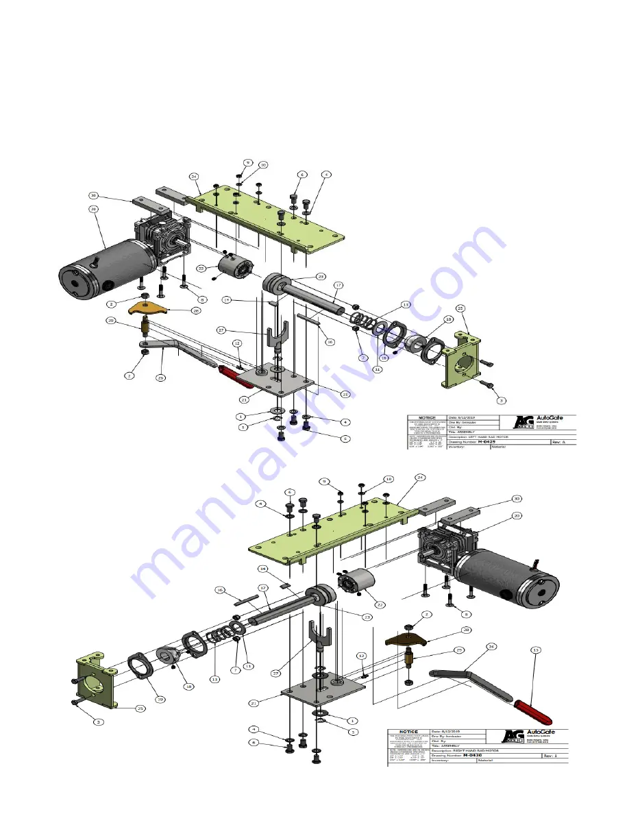
RIGHT ANGLE GEARMOTOR FIELD REPLACEMENT INSTRUCTIONS
READ INSTRUCTIONS PRIOR TO STARTING
REQUIRED TOOLS:
Workbench or other suitable flat work surface, tape measure, 9/16” wrench, 9/16” socket, 10mm
socket, ratchet, 1/8” hex key, two (2) 2x4 wood blocks approximately 9 inches long, 2” x 4” x 1/8” spacer plate or any
other flat wide tool, pen or pencil and paper.


