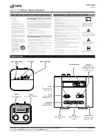
background image

M X 8 2

8   C H A N N E L   S T E R E O   M I C / L I N E   M I X E R

I N S TA L L AT I O N   A N D   O P E R AT I O N   M A N UA L

Summary of Contents for MX82

Page 1: ...MX82 8 CHANNEL STEREO MIC LINE MIXER INSTALLATION AND OPERATION MANUAL ...

Page 2: ...ng devices 13 Do not block fan intake or exhaust ports Do not operate equipment on a surface or in an environment which may impede the normal flow of air around the unit such as a bed rug weathersheet carpet or completely enclosed rack If the unit is used in an extremely dusty or smoky environment the unit should be periodically blown free of foreign matter 14 Do not remove the cover Removing the ...

Page 3: ...so available the MX82 is extremely versatile The MX82 has taken the AMIS heritage of contractor friendly installation product has added the audio fidelity needed in today s AV contracting market INTRODUCTION 3 FRONT PANEL 4 REAR PANEL 5 INTERNAL ADJUSTMENTS 6 INSTALLATION TROUBLESHOOTING 7 BASIC SETUP AND OPERATION 8 DIMENSIONS 9 BLOCK DIAGRAM 10 SPECIFICATIONS 11 AUS EUR USA Copyright 9th Feb 200...

Page 4: ...input channel is clipping use the gain trim to adjust the correct amount of input level CHANNEL TONE CONTROLS Each input has a 2 band EQ Bass 12dB 100Hz shelving Treble 9dB 10kHz shelving MIC LINE Channels 1 to 4 have a switch which controls the sensitivity of the XLR input In the off out or MIC position the XLR input is suitable for use with microphones in the on in or LINE position the XLR input...

Page 5: ...ents STEREO CHANNEL INPUTS Channels 5 to 8 are stereo line level RCA unbalanced inputs REC OUT The REC OUT output is on unbalanced RCA connectors The output is not affected by the MASTER volume control LEFT AND RIGHT OUTPUT The OUTPUT XLR s provide balanced line level signal of the left and right bus respectively NOTE When wiring the LINE output as unbalanced Pin2 should be wired as hot and Pin1 s...

Page 6: ...irst 4 channels The jumpers are located near the front of the unit When in the ON position channel 1 side signal from that channel is fed to both the master outputs and the direct outputs When the switch is in the OFF position channel 8 side signal from that channel is fed to the direct line level output only CHANNEL 1 ROUTING If channel 1 is being used as a priority input it can be routed so that...

Page 7: ...ground shield Do not wire Pin3 RECORD OUTPUT The Record output wiring should be kept as short as possible Typically less than 3m TROUBLESHOOTING GUIDE TROUBLE LIKELY CAUSE REMEDY Power LED not on Power not reaching unit Check mains connection Check mains fuse Check power switch is on Noisy output Incorrect gain structure See setup guide Distorted sound Input is overloaded Check MIC LINE switch Red...

Page 8: ...tch MIC XLR Phantom power on Input Level Controls off Output Level Control off CONNECT THE SOURCES First connect all the required sources to the appropriate input connectors If the source is a microphone set the MIC LINE switches to the MIC position If the source is an electret or condenser microphone set the phantom switch to the P P on position CONNECT THE OUTPUTS Turn the amplifiers off Connect...

Page 9: ...DIMENSIONS PAGE 9 MX82 INSTALLATION OPERATION MANUAL ...

Page 10: ...BLOCK DIAGRAM PAGE 10 MX82 INSTALLATION OPERATION MANUAL ...

Page 11: ...EVEL IN XLR mic 9dBu line 30dBu RCA 30dBu MAX LEVEL OUT 27dBu PHANTOM POWER 15V DC OUTPUTS MASTER OUT Nominal Level 0dBu into 1kohm Imp 100ohm MONO HEADPHONE OUT Nom 6dB into 200ohm Imp 10ohm MONO REC OUT Nom 12dB into 10kohm Imp 10kohm CHANNEL DIRECT OUT Nom 0dB into 1kohm Imp 100 ohm POWER INPUT AC 230V 50Hz or 115V 60Hz 3 pin IEC320 C14 connector POWER CONSUMPTION MAX 7 VA FUSES MAINS 115V 120m...

Page 12: ... 31 Walsh Street Thebarton SA 5031 PO Box 157 Hindmarsh SA 5007 Phone 08 8352 4444 Fax 08 8352 4488 Email sa audiotelex com au PERTH WA SALES 3 11 Howe Street Osborne Park WA 6017 PO Box 1281 Osborne Park BC WA 6916 Phone 08 9228 4222 Fax 08 9228 4233 Email wa audiotelex com au AUCKLAND NZ SALES 9C Piermark Drive Albany 0752 New Zealand PO Box 300 512 Albany 0752 Phone 09 415 9426 Fax 09 415 9864 ...

Reviews: