Audiovox SP-11CDS, Installation Manual
The Audiovox SP-11CDS Installation Manual is a comprehensive guide that provides step-by-step instructions for setting up and configuring the SP-11CDS audio system. Easily downloadable for free from manualshive.com, this manual ensures a hassle-free installation process, ensuring you enjoy the product's exceptional sound quality to the fullest.
Share
Download


Reviews:
No comments
Related manuals for SP-11CDS
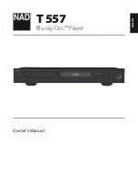
T557
Brand: NAD Pages: 28
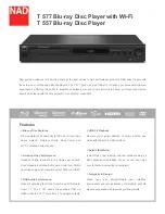
T557
Brand: NAD Pages: 2
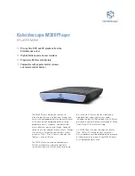
M300
Brand: Kaleidescape Pages: 2

DP540
Brand: Yosin Pages: 4

My Video Player VP320
Brand: ID-AL Pages: 4

MHD8015
Brand: Memorex Pages: 41

T-1001B
Brand: Bush Pages: 36

ODY-1995
Brand: Odyssey Pages: 12

i.Beat move M 4GB
Brand: TrekStor Pages: 2

XS200 - Gmini 20 GB Digital Player
Brand: Archos Pages: 2

DVD1040
Brand: Dolby Laboratories Pages: 16

LMD-6708Y
Brand: Axion Pages: 25

Prodigy 4K
Brand: Xtreamer Pages: 2

XV-N5
Brand: JVC Pages: 2
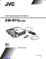
XM-R70
Brand: JVC Pages: 20

XL-Z132BK
Brand: JVC Pages: 20
XR-D400SL
Brand: JVC Pages: 28

XL-Z431BK
Brand: JVC Pages: 15


