ATX UCrypt, Operation Manual
The ATX UCrypt Operation Manual is a comprehensive guide designed to assist users in understanding and effectively operating their ATX UCrypt device. This essential manual provides step-by-step instructions and crucial information for optimal performance. Download this free manual from our website manualshive.com to unlock the full potential of your ATX UCrypt.
Share
Download


Reviews:
No comments
Related manuals for UCrypt

OFFICESERV 7100
Brand: Samsung Pages: 97

D13841.08
Brand: TANDBERG Pages: 54

ENB-302MI
Brand: SiboTech Pages: 39

GT200-PN-CO
Brand: SST Automation Pages: 32

PEACG01
Brand: Perenio Pages: 32

VIP-155PT
Brand: Planet Networking & Communication Pages: 61

SmartRG 505
Brand: Primus Pages: 2

Harmony IP I/O8
Brand: Encom Pages: 44

BeoLink 1703
Brand: Bang & Olufsen Pages: 62

DIN Gateway v2
Brand: SignalFire Pages: 31

3701A
Brand: WELLTECH Pages: 101

SG-70
Brand: SINBON Pages: 21

AnyMedia Line Access Gateway
Brand: Lucent Technologies Pages: 4

IPBX1224
Brand: Black Box Pages: 52

Pulse TV
Brand: NorthwesTel Pages: 144

SR550n
Brand: SmartRG Pages: 66

50.0070.0011.00
Brand: FP Pages: 82
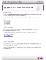
Archer VR1600v
Brand: TP-Link Pages: 5


