Atlas Copco XA 375 DD6, Instruction Manual
The Atlas Copco XA 375 DD6 Instruction Manual is essential for mastering the full potential of this powerful product. Easily accessible for free download at manualshive.com, this comprehensive manual provides step-by-step guidance on maximizing your productivity and ensuring optimal usage of the XA 375 DD6. Get yours now!
Share
Download


Reviews:
No comments
Related manuals for XA 375 DD6

VAT VE 50 L
Brand: Villager Pages: 141

Twin Bracket
Brand: ARB Pages: 6

Start-It 90550870
Brand: Black & Decker Pages: 19
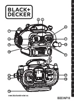
BDCINF18
Brand: Black & Decker Pages: 8
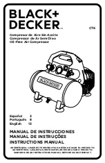
CT6
Brand: Black & Decker Pages: 17
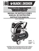
CT224
Brand: Black & Decker Pages: 24
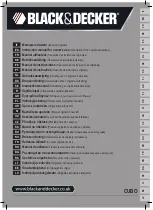
CUBO
Brand: Black & Decker Pages: 64

PTS 916 Cd
Brand: Atlas Copco Pages: 74

34207
Brand: WilTec Pages: 11

10020HDCADC
Brand: California Air Tools Pages: 17

10020SPC
Brand: California Air Tools Pages: 17

10020AC
Brand: California Air Tools Pages: 17

RCP-C43L
Brand: Hamron Pages: 15

HP600CMH
Brand: Ingersoll-Rand Pages: 44

12/235
Brand: Ingersoll-Rand Pages: 57

HP600WJD
Brand: Ingersoll-Rand Pages: 98

HYPERGRAVITY
Brand: TC Electronic Pages: 5

TH-AC 200/30 OF
Brand: EINHELL Pages: 44


