background image


Atlanta Attachment Company 

362 Industrial Park Drive 

Lawrenceville, GA 30046 

770-963-7369   •   www.atlatt.com 

                   Technical Manual & Parts Lists 

Model  

1392D 


Revision 5.3   Updated   July 15, 2016 

Summary of Contents for 1392D

Page 1: ...Atlanta Attachment Company 362 Industrial Park Drive Lawrenceville GA 30046 770 963 7369 www atlatt com Technical Manual Parts Lists Model 1392D Revision 5 3 Updated July 15 2016 ...

Page 2: ......

Page 3: ...erials contained herein are additionally protected by United States Copyright law and may not be used disclosed reproduced distributed published or sold without the express written consent of Atlanta Attachment Company which consent may be withheld in Atlanta Attachment Company s sole discretion You may not alter or remove any copyright trademark or other notice from copies of these materials IMPO...

Page 4: ...centrics 13 Setting Eccentric Top Center 13 Fine tuning Eccentric Top Center 14 Adjust Pittman rod length 14 Adjust Pittman rod length Needle bar 14 Adjusting cams for presser foot 15 Loosen up the needle bar clamps 15 Turn hand wheel to 180 15 Tighten needle lever on shaft 16 Set lowest needle position 1 16 Set lowest needle position 2 16 Set lowest needle position 3 17 Set lowest needle position...

Page 5: ... History 39 Command Buttons 40 Pendant Operations 45 Utilities 47 Log Files 48 Copy Pattern Files 49 System Information 50 Security 51 Settings 52 Efficiency Statistics 57 Assembly Drawings Parts Lists 58 11392D Quilter Golden Eagle HD 59 1389234 Panel Eye Cutter Assembly 60 1389353 Motor Guard Assembly 61 1389384 Left Guard Assembly 62 1389533 Front End Assembly 63 1389534 Bridge Assembly 64 1389...

Page 6: ...ly 94 1392580 Bag Closing Mount Assembly 95 1392897 Pleat Prevention Assembly 96 1392978 Front Feed Assembly 97 1392935 Front Left Roller Sub Assembly 98 1392936 Front Right Roller Sub Assembly 99 1392937 Front Feed Roller Sub Assembly 100 1392938 Left Sprocket Idler Assembly 101 1393922 Tensioner Assembly 102 1389023 Center Insert Mount Bearing 103 1389509 Presser Feet and Needle Bars 104 1392124...

Page 7: ...ial Tension Rack 131 1392972 LH Small Tension Clamp Assembly 132 1392973 RH Small Tension Clamp Assembly 133 1392959 Closer Assembly 134 1392151 B Pole Assembly 135 1389274 Dual Thread Break Detector Assembly 136 1393875 Footlift Adjusting Knob Assembly 138 1392291 Thread Tension Guide Assembly 139 1392304 Bearing Butterfly Assembly 140 1392846 Butterfly Drive Assembly 141 1389024 Large Eccentric ...

Page 8: ... A list of recommended spare parts Instruction Manual s for components made by other manufacturers The layout and installation diagram containing information for installation Intended Use Our machines are designed and built in line with the state of the art and the accepted safety rules However all machines may endanger the life and limb of their users and or third parties and be damaged or cause ...

Page 9: ... work on the machine is only carried out by reliable persons who have been appropriately trained for such work either within the company by our field staff or at our office and who have not only been duly appointed and authorized but are also fully familiar with the local regulations Work on the machine should only be carried out by skilled personnel under the management and supervision of a duly ...

Page 10: ...airing safety are observed in the machine or its mode of operation such as malfunctions faults or changes in the machine or tools appropriate steps must be taken immediately the machine switched off and a proper lockout tagout procedure followed The machine should be examined for obvious damage and defects at least once per shift Damage found shall be immediately remedied by a duly authorized pers...

Page 11: ...ny obstructions whatsoever is essential for safe operation of the machine The floor should be level and clean without any waste The workplace should be well lit either by the general lighting or by local lights Emergency STOP The emergency STOP buttons bring all machine movements to a standstill Make sure you know exactly where they are located and how they work Try them out Always ensure easy acc...

Page 12: ... so that it cannot be switched on again without authorization In practice this may mean that the technician electrician and operator all attach their own padlock to the master switch simultaneously so that they can carry out their work safely Locking extension plates should be available for multiple locks if required The primary purpose for a lockout tagout procedure is to protect workers from inj...

Page 13: ...hen transporting the machine or assemblies in a crate ensure that the ropes or arms of a forklift truck are positioned as close to the edge of the crate as possible The center of gravity is not necessarily in the middle of the crate Note the accident prevention regulations safety instructions and local regulations governing transport of the machine and its assemblies Only use suitable transport ve...

Page 14: ... Do not use any corrosive cleaning agents Use lint free rags Retighten all screw connections that have to be loosened for the maintenance and repair work Any safety mechanisms that have to be dismantled for setting up maintenance or repair purposes must be refitted and checked immediately after completing the work Maintenance Care Adjustment The activities and intervals specified in the Instructio...

Page 15: ...fault develops in the electrical power supply The electrical equipment of our machines must be checked at regular intervals and any defects found must be remedied immediately If it is necessary to carry out work on live parts a second person should be on hand to operate the emergency OFF switch or master switch with voltage release in the event of an emergency The working area should be cordoned o...

Page 16: ...stands this manual before operating this equipment It is also the owner s responsibility to make certain that the operator is a qualified and physically able individual properly trained in the operation of this equipment Specific safety warning decals are located on the equipment near the immediate areas of potential hazards These decals should not be removed or obliterated Replace them if they be...

Page 17: ...AXIS CENTER 47 MM 11 RETAINERS REARWARD 64º 12 REAR RETAINER BAR BACK TO BACK OF NEEDLE PLATE 64º 89MM 13 POINT OF RETAINER TO NEEDLE 154º 1 2 MM 14 LOOP TAKE TIME PT OF LPR FT OF NDL 232º 15 LOOPER TRAVEL 29 MM 16 REAR BUTTERFLY ECCENTRIC FORWARD 148º 17 BUTTERFLY STROKE RODEND CENTERED IN SLOT E 18 BUTTERFLY PITMAN ROD LENGTH 265MM 19 REAR BUTTERFLY ROD TO FRAME LOWEST POSITION 148º 38 MM F 20 R...

Page 18: ...0 Amps 3 Phase Air Pressure 90 PSI Physical Specifications Overall Dimensions 15 X 25 Weight 25000 lbs Recommended Needle SN794FR 180 Stitch Length 4 8 SPI Pressure Gauge Settings Main Pressure Regulator 70 PSI Pressure Roller Regulator 50 80 PSI Dancer Bar Regulator 5 20 PSI ...

Page 19: ...omputer PLEASE NOTE DO NOT REMOVE THE TWO GREEN USB SECURITY DONGLES FROM THE COMPUTER IF ANY OF THESE DONGLES ARE REMOVED THE EZ QUILTER SOFTWARE WILL NOT LONGER FUNCTION ONE DONGLE IS FOR THE EZ PATTERN DESIGN SOFTWARE LABELED P AND THE OTHER IS FOR THE EZ QUILT SOFTWARE LABELED Q BACK SIDE COMPUTER CONNECTIONS FRONT SIDE COMPUTER CONNECTIONS USB KEYBOARD USB MOUSE MONITOR POWER USB TOUCHSCREEN ...

Page 20: ...the highest position Tighten one bolt of eccentric Setting Eccentric Top Center Place dial indicator magnetic base on flat surface Place dial indicator tip on top of presser foot rod end bearing Rotate presser foot eccentric until the pointer of the dial indicator doesn t move anymore Tighten one bolt of the eccentric To check turn hand wheel between 345 and 15 The dial indicator needs to point at...

Page 21: ... up the 2 nuts Turn the rod until you have the right length Tighten the 2 nuts Check the final length 570mm Adjust Pittman rod length Needle bar Do the same as the presser foot Pittman rod with the Pitman rod for the needle bar Find top dead center Test top dead center with turning hand wheel from 245 up to15 Length of Pitman rod need to be 460mm Repeat this step on the other side of the machine s...

Page 22: ...ghten the bolts Bring all the cams down so they hit the cam follower then tighten the bolts Turn the shaft up so all the cams are level then tighten the bolts Tighten the levers on both sides Loosen up the needle bar clamps After adjusting the cams and followers loosen up the clamps of the needle bars Turn hand wheel to 180 ...

Page 23: ...ever Set lowest needle position 1 If not already so put the 3mm spacer under the presser foot Place the 14 3mm spacers between the presser foot and the needle bars Set lowest needle position 2 The tip of the needle should be 28mm under the throat plate when the machine is at 180 We can test this with the special gauge ...

Page 24: ...ft adjustment Set lowest needle position 4 When the needle height is 28mm under the throat plate tighten bolts of the link between needle bar and shaft Set lowest presser foot height Raise the foot up with spacers of 3mm thick Adjust the foot to its lowest position use little hand wheel The foot is at his lowest position when the key of the shaft is facing out ...

Page 25: ...Tighten bolts from clamp make sure the clams are not twisted Assemble springs on presser foot Place spring disk Place spring Place spring cap Use special tool to compress the spring and tighten spring with bolt Repeat this with all 8 presser bars Set front butterfly Turn hand wheel to 90 Level the butterfly Tighten the 3 links from shaft to butterfly shaft Turn the machine with the hand wheel The ...

Page 26: ... 3mm spacers Lift up clamp on presser foot bar so the cam followers or op against the cams Tighten bolts from clamp make sure the clams are not twisted Assemble springs on presser foot Place spring disk Place spring Place spring cap Use special tool to compress the spring and tighten spring with bolt Repeat this with all 8 presser bars ...

Page 27: ...s The modes are as follows 1 Stopped The machine is on but the servo motor controllers are off No machine movement can occur in this mode 2 Running The machine is operating normally and is quilting 3 Paused The machine is operating normally and is NOT quilting 4 Manual The user has accessed the Manual Operations Screen and can move the machine manually NOTE When leaving the Manual Operations Scree...

Page 28: ...PC Do this by clicking the red X at the extreme top right of the E Z Quilter software window For the purposes of this manual the terms Click and Double click using a mouse also refers to Pressing a button using the touch screen Main Run Screen The Main Run Screen is displayed the entire time the E Z Quilter software is active It is divided into 5 areas Machine Speed Miscellaneous Information Patte...

Page 29: ...rently running The Set RPM can be adjusted two different ways 1 There is a slider bar adjustment just below the Actual RPM display Click and hold the horizontal bar then slide back and forth to make changes 2 The two arrow buttons adjust the RPM up or down based on the increment shown in the box between the 2 buttons The increment can be set to 1 10 or 100 default is 10 The maximum RPM the machine...

Page 30: ...e the last time the Reset button was clicked Yards per Run Minute displays current thru put yards per minute The machine needs to run for at least 1 2 minutes to get an accurate reading When pausing the machine changing patterns and changing RPMs will temporarily affect this number 2 Current Mode and Batch Information For Future Use 3 Foot Height Displays the current height of the foot 4 Current S...

Page 31: ...are snug against the lower surface of the cams Do not apply excessive pressure or you will damage these bearings under a load Repeat 8X Again from left to right Place the retaining cups on the springs and tighten 8mm bolt at top of presser foot rod This may require you to hold the rod with a wrench as not to put lateral pressure on the cam followers If you cannot collapse the spring enough by hand...

Page 32: ...er the current height of the foot Foot Height adjustment is necessary based on the thickness of the materials being quilted Maximum RPM of the machine is related to the Foot Height The importance of the Foot Height is the closer the bottom of the foot is to the needle plate the higher the maximum RPM can be There are three heights associated with the foot 1 Low Maximum RPM at this height is 1275 2...

Page 33: ...here will bring up the E Z Pattern Design software with the current pattern loaded NOTE If any changes are made the pattern has to be re loaded in the E Z Quilter software Clicking the Needle Array button displays the needle arrangement needed in the machine to achieve the displayed pattern The Needle Array Code and Stitches per Inch are displayed in the box below the Needle Array button The Pinch...

Page 34: ... or decreases the percentage in which the pattern is altered when the carriage X Axis moves toward Home This is used to adjust the roundness of a circle 4 Backwards Modification Clicking the Arrow buttons increases or decreases the percentage in which the pattern is altered when the rollers Y Axis move in reverse This is used to adjust the roundness of a circle 5 Jump Modification Clicking the Arr...

Page 35: ...tern If no pattern is selected it displays the Needle Array for the first pattern in the list Clicking the Full View button will bring up the Pattern Full View screen displaying a larger view of the pattern Clicking the OK button loads the selected pattern into the machine If no pattern is selected it loads the first pattern in the list If the servos were not turned off prior to selecting the Chan...

Page 36: ...nical Manual Parts Lists 29 Pattern Full View The Pattern Full View Screen displays a larger more detailed view of the selected pattern Clicking anywhere on the screen will return you to the previous screen ...

Page 37: ...the Starting and Ending back tack is shown Needle Array Codes are sequential numbers from NA00001 to NA99999 Each number represents a unique needle array The needle array cannot be ascertained from the number only Once a code is assigned that particular arrangement will always be associated with that code Stitches per Inch Starting Back tack and Ending Back tack values can be changed resulting in ...

Page 38: ...eading the 1392 From Thread Stand 1 Take the thread behind the rod through the eyelet through the thread tensioner through another eyelet then inside the slotted thread break detector and pull down towards the needles From Thread Stand Behind Inside Slot ...

Page 39: ...hrough the guides then over another butterfly tube and then down through the guides and towards the needles Under the farthest rod Under the second rod There is another tube not shown before the eyelets that the thread also goes under Therefore the thread goes under all three bars before the eyelets Over the closest tube ...

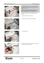
Page 40: ...Technical Manual Parts Lists 33 3 Route the thread from the rod down to the eyelets below ...

Page 41: ...ar needles are threaded by routing the thread under the middle bar and over the rear bar and down to the needles The middle needles are threaded similar to the rear needles but the thread only goes over the middle bar then down to the needles Notice the difference in routing for front and rear needle bars Front needle bar ...

Page 42: ...al Manual Parts Lists 35 Looper Thread Routing 1 Run the thread through the eyelet and thread tensioner Then take the thread over the first bar From looper thread stand Over this bar after threading tensioner ...

Page 43: ...Technical Manual Parts Lists 36 2 Route the thread over the first thread rod under the second thread rod then through the thread eyelets Over these three rods Under this rod ...

Page 44: ...oking at the loopers route thread through the last set of eyelets and under the bar with the exception of the closest looper Run thread straight from eyelet to looper Notice the thread routes under a rod before going up to looper for second row Looper ...

Page 45: ...Technical Manual Parts Lists 38 4 Once at the looper guide the thread through the back of the looper and bring it around the side then through the front of the looper ...

Page 46: ...of the machine As shown above this information consists of general information and or errors All the information displayed in this area is also written to a Log File which can be viewed on the Utilities Screen on page 47 Clicking a particular line will display a message box containing more information concerning the selected line ...

Page 47: ...he Reset Servos On button is located at the lower Left corner of the Main Run Screen When the Servos are Off this button displays the caption Reset When the Servos are On this button displays the caption Servos On When the button s caption displays Reset the servos are OFF and the machine is inoperable Clicking the button turns on power to the Servos and homes out the machine CAUTION the machine w...

Page 48: ...ws you to activate deactivate the Outputs NOTE This screen is primarily used to test the Inputs and Outputs If you manually change the state of an Input it will not have an effect on the machine However if you click on one of the Output buttons it will reverse its state if it is on it will turn off or if it is off it will turn on ...

Page 49: ...e all three axes manually and independently NOTE When moving the axes independently the synchronous relationship between them is lost Therefore when you exit this screen the machine will automatically Home Out 1 X Y Axis Jog See X Y Axis Jog on page 43 2 Z Axis Jog See on page 44 ...

Page 50: ...eft and Right directions The Arrows buttons pointing up and down move the Y Axis Roller in the Forward Up and Reverse Down directions The X Axis Position is how far the Carriage is from Home position in inches Clicking the X Axis Home Position button moves the X Axis Carriage to its Home position Only the X Axis will move ...

Page 51: ...nt displayed above Maximum reverse movement is 45 degrees The Reverse Jog and Forward Jog buttons move the Z Axis Needle in the Forward and Reverse directions and will continue to move until the respective button is released Clicking the Z Axis Home Position button move the Z Axis Needle to its Home or needle up position zero degrees Only the Z Axis will move ...

Page 52: ... any selection other than Auto NOTE Regardless of what made this screen come up you have to click the Ok button to remove it except in case of a Thread Break error Clicking the Disable Pendant button causes another button to appear labeled Index Pendant see below Clicking this button is the same as moving the selector on the physical Pendant Clicking the red or green buttons above the Index Pendan...

Page 53: ...n 2 Pause Execute Moves Z Axis to user defined position Position 3 Pause Execute Moves Z Axis to user defined position Fast Jog Reverse Forward Moves Z Axis fast till button release Max 45 in reverse Slow Jog Reverse Forward Moves Z Axis slow till button release Max 45 in reverse The Z Axis position area graphically and numerically displays the angular position of the Z Axis as it moves In case th...

Page 54: ...Status Monitors communication between the PC and the Servo Controller 4 Total Runtime Total Runtime is only accumulated when the machine is actually running in Automatic mode 5 System Information See System Information on page 50 6 Security See Security on page 51 7 Settings See Settings on page 52 8 Efficiency Statistics See Efficiency Statistics on page 57 The next few pages will provide more de...

Page 55: ...sing the same example as above the Error Log filename would be E060218 txt This file is mainly used for troubleshooting All Log Files are stored in a directory called C EZQuilt Logs NOTE Log Files are automatically deleted after a number of days defined by the Keep Log Files for Setting Clicking the Browse button allows you to navigate to a different Log file Clicking the Excel button allows you t...

Page 56: ...to Source and Browse to Destination Clicking either of these buttons will bring up the Browse screen which allows you to navigate to and select the appropriate directory Source The Source directory is the location where the files to be copied reside Examples would be a memory stick a floppy disk or a network drive Destination The Destination directory is the location where the selected files will ...

Page 57: ...rmation shows Company Information and Revision History 5 Clicking the System Information button displays configuration and hardware settings for the PC Note In order to get to the Settings screen and various other functions an increased security level is required ...

Page 58: ...ode for this level When the machine is turned on it is always at this level The codes can be changed for each level by following the instructions on the screen see above NOTE Once someone has raised the current security level to something other than Operator for example to Mechanic the machine will stay at this level until the machine is turned off or the Reset to Operator button is clicked ...

Page 59: ...Settings screen allows you to make adjustments to various aspects of how the machine functions NOTE A security level of Mechanic or higher is necessary to access this screen 7 The following pages provide more detailed information for each setting ...

Page 60: ...venient for the machine not to stop if the air pressure is low or off Removing the check mark disables the Air Sensor NOTE All air activated devices such as the undertrimmer will not function correctly without proper air pressure All Communication Errors Enable There are two channels of communication in the machine The PC communicates with the Servo Controller and the Servo Controller communicates...

Page 61: ...imes the changes cause the machine to move to farther to the right possibly causing a Right Limit Switch error When this amount of adjustment is necessary the X Home Shift setting needs to be increased A machine reset is required if the setting is changed Limits Minimum 0 Maximum 2 00 Default 50 Unit of Measure Inches Pendant Positions 1 2 and 3 Pendant Positions 1 2 and 3 are user settable needle...

Page 62: ... may loosen or tighten causing the Thread Break Detect eyes to go dark The Thread Break Debounce gives the thread time to settle down in order to report an actual thread break If this number is set too low you may get false thread break errors Conversely if set to high several stitches may pass before the operator is alerted Limits Minimum 0 Maximum 5 0 Default 1 0 Unit of Measure Seconds Undertri...

Page 63: ... Pattern Files section new patterns have to be copied to the PC running the quilter in order to be used If you normally copy from Source and or to Destination the same places you can set the defaults shown above so that any time the Copy Pattern Files section is accessed it will be pre populated with the appropriate data and Browsing will not be necessary Miscellaneous Operations Continuous Bearin...

Page 64: ...d on the amount of time the machine is in Run Mode sewing divided by the amount of time the machine is turned on Time Display changes the format the On and Run times are displayed in The Last Reset box displays the last time the Reset button was pressed resetting the On and Run Times to 0 zero 8 ...

Page 65: ...a Attachment Company In addition to any confidentiality and non disclosure obligations that currently exist between you and Atlanta Attachment Company your use of these materials serves as an acknowledgment of the confidential and proprietary nature of these materials and your duty not to make any unauthorized use or disclosure of these materials ...

Page 66: ...2 1388227 LINEAR SLIDE RR 35MM 12 1 1389384 LEFT GUARD ASSY 4 1 1388673 DRIVE 12 IN LEADSCREW 13 1 1389697 TRANSFER CARRIAGE ASSY 5 1 1389223 GUARD PANEL LEFT 14 1 1389815 MAIN DRIVE SHAFT ASM D 6 1 1389240 SUPPORT THROAT PLATE 15 2 1389893 SUPPORT THROAT PLATE 7 1 1389268 BLOCK BRG MTG FLG 16 2 1393993 RETAINER CARTRIDGE BRG 8 1 1389269 SHAFT 40MM PRESSER 17 2 BBER208TMC BEARING INSERT SKWEZLOC 9...

Page 67: ... 2X20MM 4 2 1975 412A PLATE NUT 4 40 95CTC 5 1 FFRK44T 4 CABLE EYE 12 NO END 6 1 FFRK44T 6 CABLE EYE 19 NO END 7 2 FFSM312LVQ EYE ELECTRIC 10 30VDC 8 12 in MMT9945 TAPE REFLECTIVE 2 WIDE 9 4 SSPS70048 4 40 X 3 4 PAN HD SLOTTED 10 4 SSSCM5X16 M5 0 8 X 16 SOC CAP 11 4 SSSCM6X16 M6 1 0 X 16 SOC CAP 12 4 WWF4 WASHER FLAT 4 13 4 WWFM6 6MM FLAT WASHER 14 4 WWL4 4 LW 15 4 WWLM5 M5 LOCK WASHER 16 4 WWLM6 ...

Page 68: ...D 5 1 1392404 PANEL SIDE MOTOR GUARD 6 1 1392551 LEXAN FOR 1392404 7 1 1392631 PANEL LOWER MTR GUARD 8 1 1392632 PANEL FRONT CABINET 9 1 1392634 WINDOW TOP 10 6 1392738 CLIP PANEL 11 12 NNHM5X0 8 NUT HEX M5 0 8 12 72 SSSCM5X10 SCREW SOC CAP M5 0 8 X 10 13 7 SSSCM5X14 SCREW SOC CAP M5 0 8 X 14 14 4 SSSCM5X16 M5 0 8X16 SCREW SOCKET CA 15 82 WWF10 WASHER FLAT 10 COM 16 12 WWFM5 WASHER FLAT M5 I D 17 ...

Page 69: ...20 2 SSSC70024 4 40 X 3 8 SOC CAP 6 1 1389352 COVER GUARD LH 21 2 SSSC70040 4 40 X 5 8 SOC CAP 7 1 1389391 SPACER DOOR SWITCH 22 4 SSSCM5X14 SCREW SOC CAP M5 0 8 X 14 8 6 1389401 NUT PLATE DOOR HINGE 23 18 SSSCM5X16 M5 0 8 X 16 SOC CAP 9 1 1389779 PLATE LABEL MTG 24 2 WWFS1 4 WASHER FLAT 1 4 10 1 1389816 COVER TOP LEXAN 25 22 WWFS10 WASHER FLAT 10 SAE 11 1 FF57105000 REED SWITCH MAGNET FLANGE 26 2...

Page 70: ...1 1392897 PLEAT PREVENTION ASM 7 1 1392978 FRONT FEED ASSY 8 1 1393922 TENSIONER ASSEMBLY 9 2 SSSCM10X25 10M X 25MM SOC CAP 10 4 SSSCM10X35 CAP SCREW 10MM X 35MM 11 6 SSSCM10X40 CAP SCREW 10MM X 40MM 12 12 SSSCM6X15 M6X15 SOC CAP SCREW 13 8 WWFM10 WASHER FLAT M10 I D 14 8 WWFM6 WASHER FLAT M6 SAE 15 4 WWFM6 1 WASHER FLAT M6 SAE 16 8 WWLM10 M10 LOCK WASHER 17 12 WWLM6 M6 LOCK WASHER Page 88 Page Pa...

Page 71: ...OOT SHAFT 18 2 1393986 TIE ROD ASSEMBLY NDL 6 1 1389073 ADJ NDL THD TAKEUP ASBLY 19 1 1393987 BEARING FLANGE 2BOLT 7 1 1389246 MOUNT INSERT BRG LH SPEC 20 4 1393994 MOUNT INSERT BRG ASM LH 8 1 1389509 PRESSER FEET AND NDL BARS 21 4 1393998 DRIVE NDL PS FT ASM LT 9 2 1389704 NDL SHAFT LEVER 22 4 1393999 DRIVE NDL PS FT ASM RT 10 2 1389705 PIN PIVOT NDL DRIVE LEVER 23 4 BB63032RS BEARING RADIAL SEAL...

Page 72: ...Technical Manual Parts Lists 65 ...

Page 73: ...UIDE KNIFE RAIL RIGHT 43 14 1392810 GIB RETAINER BAR FRONT 14 1 2 19A NEEDLE PLATE 44 14 1392812 GIB KNIFE BAR 15 2 2 024 ROCKER LOOPER DRIVE 45 1 AACQGY50X25 CYL AIR 1392 TRIMMER 16 6 2 026 CRANK LOOPER 46 2 AAQMC 4 4U QU MALE CONN 1 4X1 4PT 17 2 2 027 LINK LOOPER CRANK 47 6 BB51204J THRUST BEARING 18 6 2 028 PIN THREADED LOOPER CRANK 48 24 BB60042RS BEARING BALL 20 ID 42 OD 19 6 2 029 SPACER RIN...

Page 74: ... 1392071 CARRIAGE SERVO DRIVE ASM 10 1 1392082 NEEDLE BAR DRIVE ASM 11 1 1392125 REAR THREAD TENSION ASM 12 1 1392196 TAKE UP LOOPER ASM 13 1 2 047 GEAR PULLEY 84 TOOTH 14 1 2 50A SHAFT SPLINE Y AXIS 15 1 4 045A HOUSING BEARING 16 4 BB32052RS BEARING 2 ROW 25MM X 52MM 17 1 BB69122RS BEARING RADIAL SEALED 18 1 BB69162RU BEARING RADIAL SEALED 19 1 GG300L100 BELT TIMING L TYPE 20 1 GG405L150 BELT TIM...

Page 75: ...HAFT SLIDE 3 1 1389239 SPACER BEARING 4 1 1392013 BLOCK SLIDE 5 1 1392016 WELDMENT ROLLER SUPPORT 6 2 BBSMK30GUU BEARING LIN FLG 30MM 7 2 MM132 2X2 END CAP 2x2 10 14GA 8 3 SSSCM12X60 SCREW M12 X 50 9 4 SSSCM6X16 M6X16 SOC CAP SCREW 10 4 SSSCM6X35 M6X30 SOC CAP SCREW 11 3 SSSCM8X30 SCREW SOC CAP M8X30 12 3 WWFS5 16 WASHER FLAT SAE 5 16 13 3 WWL5 16 WASHER LOCK 5 16 ...

Page 76: ...Technical Manual Parts Lists 69 ...

Page 77: ... ROLLER 50 X 2900 20 1 1392146 PLATE TENSIONER MTG 21 2 1392147 SHIM TENSIONER 22 1 1392343 WELDMENT FWD CARRIAGE ROL 23 1 1392533 PLATE BRACE MTG 24 1 1392534 BLOCK STABLIZER 25 1 1392672 KEY 7MMX8MMX 96 IN 26 1 1393467 PLATE NUT M8 27 1 1393660 GUARD BELT INSIDE 28 1 1393887 BELT GUARD 29 1 1393962 BELT GUARD 30 2 BBNANFL205 25 BEARING 2 BOLT FLG 25MM 31 4 BBNAP205 25 BEARING PILLOWBLOCK 32 2 BB...

Page 78: ...Technical Manual Parts Lists 71 ...

Page 79: ...OLT MTG 15 2 1392725 FOAM NONSLIP 3 X 36 16 1 1392993 STOP DOOR LH 17 1 1392995 STOP DOOR RH 18 1 1393819 ASSY WINDOW LARGE LFT 19 2 1393820 ASSY WINDOW SMALL 20 1 1393821 ASSY WINDOW LARGE RT 21 1 EEPS21RNN7TK0 SWITCH SAFETY CABLE PULL 22 1 FF3216 STRAIN RELIEF LIQ TIGHT 23 2 FF57105000 REED SWITCH MAGNET FLANGE 24 2 FF59105010 REED SWITCH FLANGE N O 25 2 FFM1414 FIXTURE LIGHT 4 26 1 FFM4518 STRA...

Page 80: ...bly AAC Drawing Number 1389740 Rev 1 NO QTY PART DESCRIPTION 1 1 1389739 BASE ISOLATOR 2 2 MMCE235 VIBATION ISOLATOR SPRING 3 2 NNH5 8 11 NUT HEX 5 8 11 4 4 SSHC41064 5 8 11 X 1 HEX CAP SCREW 5 2 SSHC41256F 5 8 11X4 HEX CAP FULL THD 6 2 WWFS1 2 WASHER FLAT 1 2 ...

Page 81: ...TY PART DESCRIPTION 1 2 5 016 ROLLER PLATFORM 2 2 5 018 STEP WELDMENT PLATFORM 3 1 5 019 PLATFORM OPERATOR ASM 4 4 BBUCFA205 BEARING FLANGE UCFA 5 16 NNHM10X1 5 NUT HEX M10X1 5 6 8 SSHCM10X35 SCREW HEX CAP M10X35 7 8 SSSCM10X25 10M X 25MM SOC CAP 8 8 WWFM10 WASHER FLAT M10 I D 9 16 WWLM10 M10 LOCK WASHER ...

Page 82: ...Technical Manual Parts Lists 75 ...

Page 83: ...938 PLATE REFLECTOR 13 2 6 009 GUIDES THREAD 43 1 1393966 MOUNT LIGHT 14 1 6 014A EYELET BAR 44 4 BBNAP205 25 BEARING PILLOWBLOCK 15 1 6 015A TUBE EYELET BAR 45 1 FF3216 STRAIN RELIEF LIQ TIGHT 16 1 1392 002 CABLE FLUORESCENT 46 2 FFM1414 FIXTURE LIGHT 4 17 1 1975 412A PLATE NUT 4 40 95CTC 47 1 FFSM312LVQ EYE ELECTRIC 10 30VDC 18 1 1389179 MTG PLATE 48 1 MM9600K36 GROMMET RUBBER 9 16 ID 19 1 13893...

Page 84: ...Technical Manual Parts Lists 77 ...

Page 85: ...END CAP 16 1 1389236 COUPLING Y AXIS DRIVE 17 2 1392127 LOCATOR SPRING 18 2 1392128 ADAPTER COMPRESSIONSPRING 19 2 1392671 KEY 7MMX8MMX 71 IN 20 1 1392672 KEY 7MMX8MMX 96 IN 21 1 1392673 KEY 7MMX8MMX1 75 IN 22 1 1392687 KEY 6mm 23 1 1392941 WELDMENT RH REAR BRG MT 24 1 1393463 CHAIN INSIDE 36 5 L 25 2 BB60062RS BEARING BALL 30MM B 2 SL 26 3 MMH5014X30 SPROCKET 14T 5 8P 30MMB 27 2 MMH5017X30 SPROCK...

Page 86: ...RT DESCRIPTION 1 1 AAQME 4 8U QUICK MALE ELBOW 1 4X1 8 2 45 AAQME M4 M6 QUICK ELBOW CONNECTOR 3 9 AAQUT 5 5 UNION TEE 5 32 4 13 AAQUY 5 5 QUICK UNION Y 5 32 5 250 FT AATP4X2MW TUBING NYLON 5 32OD 6 2 MM78034PL INJECTOR GREEN 015CC 7 22 MM78035PL INJECTOR YELLOW 025CC 8 1 MMXGS4024 PUMP GREASE 24 STATION ...

Page 87: ...280 319 TERMBLK WAGO SENSOR DIN 4 1 1392508 DIN RAIL 35MM 12 LG 15 45 FF280 402 JUMPERS 5 1 1392689 CABLE ASSY F QUILTER I O 16 25 FF280 560 TERMBLK WAGO SENSOR DIN 6 1 AAE1392 6 SOLENOID ASSEMBLY 17 4 NNHM4X0 7 M4 X 0 7 HEX NUT 7 1 AAVF51FM1B AIR ELEC PRESSURE SW 18 2 SSSCM3X10 M3 0 5 X 10 SOC CAP 8 AR EE6X753 CABLE TIE 19 2 SSSCM5X10 M5 0 8 X 10 SOC CAP 9 2 EE8442 CABLE 2 COND 22 AWG 20 2 TTAA52...

Page 88: ...RT DESCRIPTION 1 2 1392497 BRACKET LIMIT SWITCH 2 2 FFGLLA01A1B SWITCH LIMIT ROLLER ARM 3 2 FFM4518 STRAIN RELIEF LIQ TIGHT 4 4 SSSCM4X30 SCREW SOC CAP M4 0 7X30 5 4 SSSCM5X16 SCREW SOC CAP M5 0 8 X 16 6 4 WWFM4 3 WASHER FLAT M4 7 4 WWFM5 WASHER FLAT M5 I D 8 4 WWL8 WASHER LOCK 8 9 4 WWLM5 M5 LOCK WASHER ...

Page 89: ...ng Number 1392898 Rev 4 NO QTY PART DESCRIPTION 1 1 1392501 IDLER BEARING ASSEMBLY 2 1 1393968 DRIVE IDLER WELDMENT 3 2 NNJM8 NUT JAM M8 ZINC PLATED 4 2 SSSCM8X25 SCREW SOC CAP M8X25 5 1 SSSCM10X25 10M X 25MM SOC CAP 6 1 WWF3 8 WASHER FLAT 3 8 OR 10MM 7 1 WWLM10 M10 LOCK WASHER ...

Page 90: ...er 192121B Rev 2 NO QTY PART DESCRIPTION 1 2 KQR07 09 Reducing Fitting 2 6 SY3140 5LZ Solenoid 3 1 SX3000 53 1A Left Cap End 4 1 SX3000 52 1A Right Cap End 5 2 SX3000 51 15A Block 6 6 SX3000 50 1A N7 Block Assy 7 5 38 VZ1000 11 1 9 Din Rail 8 2 AN203 KM8 Port Silencer 9 3 KQ2P 07 Plug ...

Page 91: ... 2 1 AA198 5110 FILTER REGULATOR LOCKOUT 3 2 AAQME 4 4 ELBOW MALE 1 4X1 4NPT 4 4 AAQME 4 8 ELBOW QUICK MALE 1 4X1 8 5 1 AAV125B PILOT VALVE 6 2 MM4554K11 PLUG 1 8 PIPE 7 2 NNK1 4 20 NUT HEX KEP 1 4 20 W LOCK 8 2 NNK6 32 KEP NUT 6 32 9 2 SSPS80080 6 32 X 3 8 LG PAN HD 10 2 SSSC01048 1 4 20 X 3 4 SOC CAP SC 11 4 WWFS1 4 WASHER FLAT SAE 1 4 12 4 WWFS6 WASHER FLAT 6 ...

Page 92: ...Technical Manual Parts Lists 85 ...

Page 93: ...F280 402 JUMPER WAGO 280 SINGLE 20 10 FF280 901 TERMBLK WAGO TOP SNGL GRY 21 3 FF280 907 TERMBLK WAGO TOP SNGL GRN 22 10 FT FF3077 1 WIRE STR 16 PVC WHT 23 10 FT FF3077 2 WIRE STR 16 PVC BLK 24 10 FT FF3077 3 WIRE STR 16 PVC RED 25 10 FT FF8908 2 WIRE STR 8 PVC RED 26 10 FT FF8908 10 WIRE STR 8 PVC BLK 27 10 FT FF8908 13 WIRE STR 8 PVC BLU 28 4 FT FF9740 CABLE 2 COND 18 AWG 300V 29 10 FT FF9912 2 ...

Page 94: ...Technical Manual Parts Lists 87 ...

Page 95: ...0 24X1 1 4 13 2 1392727 STOP FRONT GUARD 42 2 SSPSM4X16 M4 0 70X16 PAN HS SLOTTED 14 1 1392943 FRAME FRONT COVER 43 2 SSSC98080 10 32 X 1 1 4 SOC CAP 15 1 1392953 COVER FRONT LEXAN L 44 2 SSSC98096 10 32 X 1 1 2 SOC CAP 16 4 AA198RA508 FLOW CONTROL 5 32 X 1 8 45 8 SSSCM5X10 SCREW SOC CAP M5 0 8 X 10 17 2 AAC127DP CYLINDER AIR DA 7 STK 46 4 SSSCM5X35 SCREW SOCKET CAP M5X5 18 2 AAFBP 25C BRKT PIVOT ...

Page 96: ...Technical Manual Parts Lists 89 ...

Page 97: ... 412A PLATE NUT 4 40 95CTC 14 4 BB1L017 BEARING BALL 787B 15 2 CCCL24F CLAMP COLLAR 1 5 BORE 16 1 EERL105 REFLECTOR RECTANGULAR 17 1 EEST03 ADAPTER RIGHT ANGLE 18 1 FFRK44T 4 CABLE EYE 12 NO END 19 1 FFSM312LVQ EYE ELECTRIC 10 30VDC 20 2 MMGP 105 GRIP HANDLE FOAM 3 4 ID 21 2 NNE6 32 NUT ELASTIC LOCK 6 32 22 6 NNH5 16 18 5 16 18 HEX NUT 23 2 SSBC80024 6 32 X 3 16 BUT HEAD 24 8 SSBCM5X8 SCREW BUTTON...

Page 98: ...ual Parts Lists 91 1393940 Regulator Valve Assembly AAC Drawing Number 1393940 Rev 1 NO QTY PART DESCRIPTION 1 1 1393939 PLATE VALVE REG MTG 2 3 AAQME 4 4 ELBOW MALE 1 4X1 4NPT 3 1 AAVH202 N02 VALVE HAND 2 POSITION ...

Page 99: ...l Parts Lists 92 1392306 Roller Lift Assembly AAC Drawing Number 1392306 Rev 3 NO QTY PART DESCRIPTION 1 1 1389085 ROLLER LIFT ASSEMBLY LT 2 1 1392095 ROLLER LIFT ASSEMBLY 3 2 1393895 COLLAR END PLAY 4 1 3 005 ROLLER ...

Page 100: ...Technical Manual Parts Lists 93 ...

Page 101: ...X30 SCREW SOCKET CA 12 1 1392904 SUPPORT TENSION ROLLER 39 12 SSSCM6X20 SCREW SOCKET CAP 13 2 1392908 COVER TENSION ROLLER BRG 40 6 SSSCM6X25 M6X25 SOC CAP SCREW 14 1 1392913 COVER TOP LEFT 41 4 SSSCM8X20 M8X20 SOC CAP 15 1 1392914 COVER TOP RIGHT 42 4 SSSCM8X25 SCREW SOC CAP M8X25 16 2 1393466 CHAIN SINGLE STRAND 43 4 SSSCM8X30 SCREW SOC CAP M8X30 17 1 1394146 SUPPORT WHEEL ASSY 44 4 SSSSM5X5C M5...

Page 102: ...38 BRACKET 8 1 1392959 CLOSER ASSM 9 1 MM331 CLAMP PULL LATCH 10 1 MMHGR30R3000HN RAIL LINEAR HG 3000MM 11 1 MMHGW30HCZ0HN LINEAR BEARING 12 1 NNHM8X1 25 M8 X 1 25 HEX NUT 13 9 SSSCM6X10 M6X10 SOC CAP SCREW 14 2 SSSCM6X12 M6X12 SOC CAP SCREW 15 4 SSSCM6X15 M6X15 SOC CAP SCREW 16 1 SSSCM6X45 M6X45 SOC CAP SCREW 17 9 SSSCM8X20 M8X20 SOC CAP 18 4 SSSCM8X25 SCREW SOC CAP M8X25 19 1 SSSCM8X35 SCREW SOC...

Page 103: ...OTOR 3 1 1392645 GUARD MOTOR 4 1 1392693 MOTOR ASSY SPIRAL ROLLER 5 1 1961 369 PULLEY CLUTCH 20T 3 8 6 1 GG285L050 BELT 3 8P 76T 1 2W 7 1 SSSCM5X16 SCREW SOC CAP M5 0 8 X 16 8 1 SSSCM5X8 SCREW SOC CAP M5 0 8 X 8 9 4 SSSCM6X20 SCREW SOCKET CAP 10 4 WWF1 4 WASHER FLAT 1 4 COM 11 2 WWFS10 WASHER FLAT 10 SAE 12 1 WWL10 WASHER LOCK 10 13 4 WWLM6 M6 LOCK WASHER Page 135 Page ...

Page 104: ...LOTH PLATE SUPPORT ARM 5 1 1392816 ROLLER INPUT MODIFIED 18 2 MM050526 TAPE SANDPAPER 240 GRIT 6 1 1392879 ROLLER INPUT 19 12 SSFCM5X10 SCREW FLAT ALLEN CAP 7 1 1392909 GUIDE PLATE INFEED RIGHT 20 17 SSSCM5X10 SCREW SOC CAP M5 0 8 X 10 8 1 1392921 GUARD FRONT ROLLER RT 21 6 SSSCM6X55 M6X55 SOC CAP SCREW 9 1 1392925 GUARD FRONT ROLLER LT 22 6 WWFM6 1 WASHER FLAT M6 SAE 10 1 1392933 LEFT GUARD INSER...

Page 105: ... X 60 SOC CAP 6 2 1392883 SPACER FLANGE BEARING 22 1 SSSCM12X90 STUD M12X40 W SHOULDER 7 2 1392886 MOUNT CYLINDER BASE 23 2 SSSCM8X20 M8 1 25 X 20 SOC CAP 8 1 1392890 SHAFT PIVOT 25MM 24 3 WWFM12 12MMFLAT WASHER 9 1 1392891 LEFT CARRIAGE FRAME 25 2 WWFS3 8 WASHER FLAT 3 8 10 2 4 039 ADAPTER CLUTCH BEARING 26 1 WWFS5 16 WASHER FLAT 5 16 11 2 AA198RA404U FLOW CONTROL 1 4PTX1 4 27 2 WWFS7 16 7 16 FW ...

Page 106: ...75 X 30 SOC CAP 4 1 1392892 RIGHT CARIAGE FRAME 15 1 SSSCM12X35 M12 1 75 X 35 SOC CAP 5 2 AA198RA404U FLOW CONTROL 1 4PTX1 4 16 1 SSSCM12X90 STUD M12X40 W SHOULDER 6 1 AAC313DXP CYLINDER AIR 2 BORE 3 STK 17 2 SSSCM8X20 M8 1 25 X 20 SOC CAP 7 1 BBAW 8Z BEARING ROD END FEMALE 18 3 WWFM12 12MMFLAT WASHER 8 4 BBUCFL205 BEARING FLANGE UCFL 19 2 WWFS3 8 WASHER FLAT 3 8 9 1 NNE5 16 18 NUT ELASTIC LOCK 5 ...

Page 107: ... 2 1 1392869 SUPPORT LINK BEARING 3 1 1392870 SUPPORT LINK BEARING 4 1 1392871 STEEL SPROCKET 17T 5 8P 5 1 1392872 ROLLER DRIVEN FRONT 6 4 BBUCFL205 BEARING FLANGE UCFL 7 2 WWFM12 WASHER FLAT M12 I D 8 2 NNHM12X1 75 NUT HEX M12 9 1 SSHCM8X60 SCREW HEX CAP M8X60 10 6 WWL1 2 1 2 LOCK WASHER 11 4 SSSCM12X30 SCREW SOC CAP M12 X 30 12 2 SSSCM12X60 SCREW M12 X 50 ...

Page 108: ...DLER SPROCKET ASSEMBLY 2 1 1392820 PLATE ADAPTOR BEARING 3 1 1392853 SHAFT MOUNT M20X2 5 4 1 1392867 SHAFT MOUNT M20X2 5 5 4 CCCL16F COLLAR 1 CLAMP TYPE 6 2 MMN2 TIGHTENER SHAFT 1 DIA 7 2 SSSCM12X25 SCREW M12 X 25 8 2 SSSCM12X30 SCREW SOC CAP M12 X 30 9 3 SSSCM12X35 SCREW M12 X 35 10 2 WWFM12 WASHER FLAT M12 I D 11 5 WWLM12 M12 LOCK WASHER ...

Page 109: ...9188 SPACER 3 4 X 3 X 3 1 2 2 2 1389189 SHAFT PIVOT TENSION BARS 3 2 1389469 KNOB THREADED M8 4 2 1389522 SPACER 3 4 X 3 X 1 3 4 5 2 1389617 ROD STOP TENSION BARS 6 2 1393927 ARM PIVOT 7 2 1393928 PLATE TENSION BAR MTG 8 1 3 017 FRONT TENSIONER MOD 9 16 SSSCM8X25 SCREW SOC CAP M8X25 10 2 TTH6324K63 HANDLE THREADED M8 X 20 MM ...

Page 110: ...umber 1389023 Rev 2 NO QTY PART DESCRIPTION 1 4 1393993 RETAINER CARTRIDGE BRG 2 1 1393995 MOUNT INSERT BRG CENTER 3 6 AAF3 16 CLAMP BLACK PLASTIC 4 4 BBER208TMC BEARING INSERT SKWEZLOC 5 6 SSBCM5X16 M5 0 8 X 16 BUTTON CAP 6 10 SSSCM5X10 M5 0 8 X 10 SOC CAP 7 16 WWLM5 M5 LOCK WASHER ...

Page 111: ...DDLE 5 3 1393901 NEEDLE CLAMP LEFT 6 6 1393902 PLATE WASHER 7 2 1393921 PLATE SPLICE FOOT 8 1 1393925 PRESSER FOOT RH 9 1 1393926 PRESSER FOOT LH 10 16 1393952 PLATE ADAPTER 11 40 1393953 WASHER HEAVY 12 50 SSSCM5X10 SCREW SOC CAP M5 0 8 X 10 13 24 SSSCM6X12 M6X12 SOC CAP SCREW 14 30 SSSCM6X25 M6X25 SOC CAP SCREW 15 50 WWFM5 WASHER FLAT M5 I D 16 24 WWFM6 WASHER FLAT M6 SAE 17 30 WWFS1 4 WASHER FL...

Page 112: ...92359 TUBE THREAD GUIDE 1 046 7 2 1392668 SUPPORT THREAD GUIDE 8 2 1392670 SUPPORT THREAD GUIDE 9 7 1393862 EXTENSION SHAFT CYL 10 7 AACSDA20X10 CYLINDER 11 14 AAQME 4 10 ELBOW QUICK MALE 12 1 FFRK44T 4 CABLE EYE 12 NO END 13 2 FFRK44T 6 CABLE EYE 19 NO END 14 1 FFS18SN6RQ EYE OPPOSED RCVR NPN IR 15 2 FFS186EQ EYE OPPOSED XMIT IR LED 16 6 SSAS016128 SHOULDER BOLT 1 4 X 2 0L 17 49 SSSCM5X14 SCREW S...

Page 113: ...8 1392019 BLOCK THREAD ROD 9 2 1392066 THREAD GUIDE ROD FRONT 10 8 1392686 KEY 6mm 11 10 1392811 BAR CLAMP BUTTERFLY 12 2 1392844 TUBE BUTTERFLY 13 3 1392846 BUTTERFLY DRIVE ASSY 14 8 1392847 BRKT EYELET BAR MTG 15 1 1392849 SHAFT BUTTERFLY 25MM 16 1 1393865 SHAFT FOOTLIFT ADJUST 17 1 1393875 FOOTLIFT ADJUST KNOB ASSY 18 1 1393955 BAR EYELET 19 4 1393958 FOOTLIFT LINKAGE LEFT 20 4 1393957 FOOTLIFT...

Page 114: ...ight Hand Bearing AAC Drawing Number 1389199 Rev 1 NO QTY PART DESCRIPTION 1 1 1392815 BLOCK BEARING 2 1 BBGE20ES2RS BEARING SPHERICAL PLAIN 2 3 1 BBGER205 25 BEARING BALL 25MMB CLAMP 4 6 SSBCM5X8 M5 X 8MM BUT HEAD 5 6 WWFM5 WASHER FLAT M5 I D ...

Page 115: ...Left Hand Bearing AAC Drawing Number 1389200 Rev 0 NO QTY PART DESCRIPTION 1 1 1392815 BLOCK BEARING 2 1 BBGE20ES2RS BEARING SPHERICAL PLAIN 2 3 1 BBGER205 25 BEARING BALL 25MMB CLAMP 4 6 SSBCM5X8 SCREW BUTTON CAP 5 6 WWFM5 WASHER FLAT M5 I D ...

Page 116: ...ists 109 1393986 Tie Rod Assembly AAC Drawing Number 1393986 Rev 1 NO QTY PART DESCRIPTION 1 1 1392719 TIE ROD WELDMENT NDL 2 1 1393984 NUT TIE ROD RH THREAD 3 1 1393985 NUT TIE ROD LH THREAD 4 6 SSSSM6X10 M6 SET SCREW 10MM L ...

Page 117: ...g Number 1393994 Rev 2 NO QTY PART DESCRIPTION 1 1 1393992 MOUNT INSERT BEARING 2 2 1393993 RETAINER CARTRIDGE BRG 3 3 AAF3 16 CLAMP BLACK PLASTIC 4 2 BBER208TMC BEARING INSERT SKWEZLOC 5 3 SSBCM5X12S SCREW BUTTON CAP S S 6 5 SSSCM5X10 SCREW SOC CAP M5 0 8 X 10 7 8 WWLM5 M5 LOCK WASHER ...

Page 118: ...1 BRACKET BELLOW 4 25 ID 4 2 4 088 MOUNT ROLLER BEARING 14 2 1389302 BRACKET BELLOW 4 25 ID 5 2 1388672 BRKT BELLOWS NEW 1392 15 2 BB30306 BEARING TAPPERED 6 1 1388716 NUT PLATE LEAD SCREW 16 2 BB60062RS BEARING BALL 30MM B 2 SL 7 1 1389292 SHAFT DRIVE EXTENDED 17 2 MM9740K16 BELLOW 4 25 ID ZIPPER 8 1 1389293M MOUNT ROLLER BEARING 18 2 MM98409A003 RETAINING RING INT 2 188B 9 1 1389296M MOUNT ROLLE...

Page 119: ...DE 16 3 4 3E 07 GEARBOX SPIRAL BEVEL 5 2 3 023 PLATE SIDE PULLEY 17 3 BB22022 BEARING BALL 15ID 35OD 6 3 1386653 SPACER BEARING 18 2 BB69052 BEARING RADIAL SEALED 7 1 1389381 SHAFT SPREADER DRIVE RT 19 2 BBNAP2 BEARING PILLOWBLOCK 8 1 1389382 SHAFT SPREADR DRIVE LEFT 20 1 GG240L BELT GEAR 3 8P 1 1 2W 9 1 1389383 COUPLING OFFSET OLDHAM 21 3 MM984 E RING INT 1 3 8 X 051 10 3 1389488 MOUNT GEARBOX RE...

Page 120: ...ical Manual Parts Lists 113 1389383 Oldham Offset Coupling AAC Drawing Number 1389383 Rev 0 NO QTY PART DESCRIPTION 1 2 1389402 COUPLING HALF 2 1 1389403 SPIDER FOR COUPLING 3 4 SSSSM8X10 M8X10 SOC SET SCRW ...

Page 121: ...s Lists 114 1392991 U Joint Retainer Assembly AAC Drawing Number 1392991 Rev 1 NO QTY PART DESCRIPTION 1 1 1392990 U JOINT MOD 2 1 UJCJ6489K BOOT UNIVERSAL JOINT 3 2 EE6X750 TIE WRAP Small 4 4 SSSCM6X12 M6X12 SOC CAP SCREW ...

Page 122: ...Technical Manual Parts Lists 115 ...

Page 123: ...NG PRESSER 12 1 RRLC135M04 SPRING COMP 13 2 BBNA4901A2R BEARING NEEDLE 12MM 14 2 MM1105K71 GREASE FITTING M6X1 15 1 MM5909K71 WASHER THRUST 10MM ID 16 3 MM5909K72 WASHER THRUST 12MM ID 17 4 MM98541A139 RETAINING RING 32MM 18 1 SSASM12M16 SCREW ALLEN SHOULDER 19 1 SSASM12M25 SCREW ALLEN SHOULDER 20 1 SSHCM8X20 SCREW HEX CAP 21 4 SSSCM6X12 M6X12 SOC CAP SCREW 22 4 SSSCM6X25 M6X25 SOC CAP SCREW 23 1 ...

Page 124: ...Technical Manual Parts Lists 117 ...

Page 125: ...E SPRING PRESSER FT 12 1 RRLC135M04M SPRING COMP 135X1 09X3 13 2 BBNA4901A2RSR BEARING NEEDLE 12MM ID 14 2 MM1105K71 GREASE FITTING M6X1 15 1 MM5909K71 WASHER THRUST 10MM ID 16 3 MM5909K72 WASHER THRUST 12MM ID 17 4 MM98541A139 RETAINING RING 32MM EXT 18 1 SSASM12M16 SCREW ALLEN SHOULDER 19 1 SSASM12M25 SCREW ALLEN SHOULDER 20 1 SSHCM8X20 SCREW HEX CAP 21 4 SSSCM6X12 M6X12 SOC CAP SCREW 22 4 SSSCM...

Page 126: ...Technical Manual Parts Lists 119 ...

Page 127: ...2 7 BB1208K BEARING TAPPERED BORE 7 4 2 062 ECCENTRIC INSERT LARGE 23 4 BB60132RS BEARING RADIAL SEALED 8 4 2 063A ECCENTRIC LINKAGE 24 4 BB60162RS BEARING RADIAL SEALED 9 4 2 064B ECCENTRIC INSERT SMALL 25 2 BB62022RS BEARING RADIAL SEALED 10 4 2 065 CAP LOOPER ECENTRIC 26 7 BBH208 SLEEVE ADAPTER 11 2 3 023 PLATE SIDE PULLEY 27 2 BBUKFL208 BEARING FLANGE UKFL 12 1 3 028A PULLEY GEAR 40MM WIDE 28 ...

Page 128: ...l Parts Lists 121 1392070 Roll Servo Drive Assembly AAC Drawing Number 1392070 Rev 1 NO QTY PART DESCRIPTION 1 1 1392809 PULLEY GEAR 38MM WIDE 2 1 C302N0410MT20 GEARBOX CONC HELICAL 3 1 SGMPH15AAE41D MOTOR SERVO 1 5KW ...

Page 129: ...1392071 Carriage Servo Drive Assembly AAC Drawing Number 1392071 Rev 0 NO QTY PART DESCRIPTION 1 1 1 034 PULLEY TIMING 18T 2 1 2 033 M MOUNT MOTOR 3 1 2 046 BRACKET MOTOR 4 1 6 010A SPACER MOTOR MOUNT 5 1 SGMGH30ACA61 MOTOR SERVO 3 0KW ...

Page 130: ...ION 1 1 1389827 PULLEY GEAR L 38MM WIDE 2 1 1392261 SPACER MOTOR BASE 3 1 1392499 MOUNT MOTOR BOTTOM 4 1 1392654 MOUNT MOTOR BASE 5 1 1392741 WASHER PULLEY 6 1 SGMGH30ACA61 MOTOR SERVO 3 0KW 7 1 SSSCM12X30 SCREW SOC CAP M12 X 30 8 2 SSSSM6X10 M6 SET SCREW 10MM L 9 1 WWFM12 WASHER FLAT M12 I D 10 1 WWLM12 M12 LOCK WASHER ...

Page 131: ... 10 AAQME 4 10 ELBOW QUICK MALE 3 1 1389271 THREAD BREAK DETECTOR 11 2 FFRK44T 4 CABLE EYE 12 NO END 4 1 1389455 PLATE TENSION RELEASE 12 1 FFRK44T 6 CABLE EYE 19 NO END 5 91 1389915 WASHER THREAD TENS 13 1 FFS18SN6RQ EYE OPPOSED RCVR NPN IR 6 91 1392126 SPACER THREAD TENSION 14 2 FFS186EQ EYE OPPOSED XMIT IR LED 7 AR 1392557 GUIDE THREAD TENSIONER 15 91 SCT1392L TENSION ASSY 1392 LOOPER 8 91 1392...

Page 132: ...RIPTION 1 2 2 081 DRIVE ARM REAR BTRFLY 2 2 4 051 GUIDE THREAD ROD 3 1 4 052 SHAFT REAR TAKE UP 4 1 4 053 ROD REAR TAKE UP 5 5 4 083 TAKE UP THREAD ROCKER 6 1 4 084A GUIDES THREAD 7 2 5 033 SHAFT RODEND REAR BTRFLY 8 7 1392304 BUTTERFLY BEARING ASSY 9 1 1392983 ROD SUPPORT REAR THREAD 10 2 CCCLM20F CLAMP COLLAR M20 ...

Page 133: ...l Parts Lists 126 1389575 Torque Limit Assembly AAC Drawing Number 1389575 Rev 1 NO QTY PART DESCRIPTION 1 1 1389569 HUB MODIFIED 22MM B 2 1 BB250AX_540 BUSHING 54L FOR TORQUE L 3 1 MM250AG517 SPROCKET TORQUE LIMITER ...

Page 134: ...wing Number 1392230 Rev 1 NO QTY PART DESCRIPTION 1 1 1392466 GUARD BASE FIXTURE S 2 1 1392561 GUARD BASE ASSM L 3 1 1392562 GUARD CLOSURE L 4 1 1392564 GUARD CLOSURE S 5 14 SSSCM5X10 SCREW SOC CAP M5 0 8 X 10 6 14 WWFM5 WASHER FLAT M5 I D 7 14 WWLM5 M5 LOCK WASHER ...

Page 135: ...LATE REGULATOR MTG 2 3 31103701 BRKT PRESSURE GAUGE 3 1 AA198 5031 0 160PSI AIR GAGE 1 8NPT 4 2 AA198 5032 0 60PSI AIR GAGE 1 8NPT 5 3 AA198 RP3 REGULATOR PRECISION AIR 6 3 AAF10289 T FITTING 1 4 NPT 7 3 AAQMC 5 8 QU MALE CONN 5 32X1 8 8 6 AAQME 4 4 ELBOW MALE 1 4X1 4NPT 9 3 AAQME 5 8 QUICK MALE ELBOW 10 3 MM4554K11 PLUG 1 8 PIPE ...

Page 136: ...Technical Manual Parts Lists 129 ...

Page 137: ...NK OUT 11 1 EEJEPMCCM2300 COMM CARD RS232 ETHERNET 12 1 EEJEPMCMP2300 CONTROLLER MOTION 13 1 EEJEPMCOP300 RAIL CLIP MP2300 14 1 EEJEPMCOP2300 SLOT COVER 15 30 EETS35X7 5A DIN RAIL AMERICAN 16 2 FF280 308 TERMBLK ENDPLATE WAGO 280 17 14 FF280 402 JUMPER WAGO TOP SNGL 18 42 FF280 901 TERMBLK WAGO TOP SNGL GRY 19 4 FF280 907 TERMBLK WAGO TOP SNGL GRN 20 1 FF3077 2 WIRE 16 AWG BLACK 21 1 FF3077 3 WIRE...

Page 138: ...1392542 PLATE CAP FRICTION BRAKE 5 1 1392543 BLOCK DELRIN S 6 1 1393802 3 8 24 X 2 HEX HEAD FULL THD 7 1 1393803 NUT WING 3 8 24 8 1 MM331 CLAMP PULL LATCH 9 1 NNE1 4 20 NUT ELASTIC LOCK 1 4 20 10 1 SSSC01192 1 4 20 X 3 SOC CAP 11 6 SSSCM6X20 SCREW SOCKET CAP 12 2 SSSSM3X8 M3 SET SCREW 8MM L 13 1 TTK32315 KNOB 1 7 8OD 3 8B BLACK 14 1 WWFS3 8 WASHER FLAT SAE 3 8 15 6 WWLM6 M6 LOCK WASHER 16 1 WWS30...

Page 139: ...BLOCK DELRIN S 5 1 1392964 MATERIAL BRKT 6 1 1393802 3 8 24 X 2 HEX HEAD FULL 7 1 1393803 NUT WING 3 8 24 8 1 MM331 CLAMP PULL ACTION 700LB 9 1 NNE1 4 20 NUT ELASTIC LOCK 1 4 20 10 1 SSSC01192 1 4 20 X 3 SOC CAP 11 6 SSSCM6X20 M6 X 20 SOC CAP 12 1 SSSS98016 SCREW SKT SET FLAT POINT 13 2 SSSSM3X8 M3 SET SCREW 8MM L 14 1 TTK32315 KNOB 1 7 8OD 3 8B BLACK 15 1 WWFS3 8 WASHER FLAT SAE 3 8 16 6 WWLM6 WA...

Page 140: ...ON BRAKE 4 1 1392543 BLOCK DELRIN S 5 1 1392966 MATERIAL BRKT 6 1 1393802 3 8 24 X 2 HEX HEAD FULL THD 7 1 1393803 NUT WING 3 8 24 8 1 MM331 CLAMP PULL LATCH 9 1 NNE1 4 20 NUT ELASTIC LOCK 1 4 20 10 2 SSSSM3X8 M3 SET SCREW 8MM L 11 6 WWLM6 M6 LOCK WASHER 12 6 SSSCM6X20 SCREW SOCKET CAP 13 1 TTK32315 KNOB 1 7 8OD 3 8B BLACK 14 1 SSSC01192 1 4 20 X 3 SOC CAP 15 1 WWFS3 8 WASHER FLAT SAE 3 8 16 1 WWS...

Page 141: ... 3 SSSCM6X12 M6X12 SOC CAP SCREW 4 1 1392163 SUPPORT BASE BAG CLOSER 15 1 SSSCM6X45 M6X45 SOC CAP SCREW 5 1 1392960 GUARD BELT 16 3 WWFM5 WASHER FLAT M5 I D 6 1 1393836 BRACKET HANDLE 17 1 WWFS1 4 WASHER FLAT SAE 1 4 7 1 BC 1 BORDER CLOSER MACHINE 18 3 WWLM5 M5 LOCK WASHER 8 1 FF770018 1 PLUG 3 POS UML2 19 3 WWLM6 WASHER LOCK M6 9 3 FF770251 3 CONN UML2 PIN F 14 20 17 ft ZTH3 4B HEAT SHRINK TUBING...

Page 142: ...ists 135 1392151 B Pole Assembly AAC Drawing Number 1392151 Rev 1 NO QTY PART DESCRIPTION 1 1 1392110 ROLL SPIRAL FLIGHTED 2 2 1392150 MOUNTING BLK BEARING 3 1 1392156 PULLEY CLUTCH 20T 25mm 4 2 BBNAP205 25 BEARING PILLOWBLOCK ...

Page 143: ...TY PART DESCRIPTION 1 50 1386421 THREAD BREAK DETECT MOD 2 3 1388717 BRACKET SENSOR NEW STYLE 3 1 1389275 PLATE DUAL THREAD STOP 4 42 1392325 STAND OFF RAIL 5 6 1392326 BAR SENSOR MTG MIDDLE 6 3 1392902 PLATE NUT M5X27 7 42 SSFCM5X35 SCREW FLAT ALLEN CAP 8 6 SSSCM5X40 SCREW SOCKET CAP M5X40 9 6 WWLM5 M5 LOCK WASHER ...

Page 144: ...Technical Manual Parts Lists 137 ...

Page 145: ... PLATE COVER FOOT ADJ 11 1 1392710 PLATE SENSOR MTG 12 1 1392998 WHEEL FOOT LIFT 13 1 1393878 BRKT FOOR ADJ MTG 14 2 1393882 BRKT REAR 15 1 BBTRA815 WASHER THRUST STEEL 1 2 16 2 CCCL8F CLAMP COLLAR 1 2 17 2 FFGXL8FC5 PROX SWITCH 18 1 MM57545K527 WORM 12P 1 0 OD 0 5B 19 2 SSSCM2 5X8 M2 5 0 45 X 8 SOC CAP 20 12 SSSCM5X16 M5 0 8 X 16 SOC CAP 21 2 SSSCM6X10 M6 1 0 X 10 SOC CAP 22 8 SSSCM6X16 M6 1 0 X ...

Page 146: ...nsion Guide Assembly AAC Drawing Number 1392291 Rev 7 NO QTY PART DESCRIPTION 1 107 1389915 WASHER THREAD TENS OPEN 2 1 1392290 GUIDE THREAD GUIDE 3 107 1392308 SPACER THREAD TENSION 4 107 1392987 PIN TENSION OPENER LONG 5 107 SCT1392 TENSION ASSY 1392 ...

Page 147: ...utterfly Assembly AAC Drawing Number 1392304 Rev 0 NO QTY PART DESCRIPTION 1 1 1392221 GUIDE LOOPER THREAD 4 082A 2 2 1 1392491 MOUNT ROLLER BEARING 3 1 BB60042RS BEARING BALL 20 ID 42 OD 4 2 SSSCM5X16 SCREW SOC CAP M5 0 8 X 16 5 2 WWLM5 M5 LOCK WASHER ...

Page 148: ...ANK FRONT BUTTERFLY 2 1 1392835 CRANK FRONT BUTTERFLY 3 1 1392836 LINK BUTTERFLY DRIVE 4 2 BBAS1226 WASHER THRUST 12MM ID 5 2 BBNA4901A2RSR BEARING NEEDLE 12MM ID 6 2 MM1105K71 GREASE FITTING M6X1 7 2 MM5909K71 WASHER THRUST 10MM ID 8 2 SSASM12M25 SCREW ALLEN SHOULDER 9 4 SSSCM8X30 M8 1 25 X 30 SOC CAP 10 4 SSSCM8X35 M8 1 25 X 35 SOC CAP ...

Page 149: ...y AAC Drawing Number 1389024 Rev 3 NO QTY PART DESCRIPTION 1 1 2 060 NEEDLE BAR ECCENTRICS 2 1 2 061 NDL BAR ECCENTRIC PLATE 3 1 2 062M ECCENTRIC INSERT LARGE 4 1 BB60162RS BEARING RADIAL SEALED 5 1 MMN1302475 RING RET BLVD INT 4 75 6 2 SSSSM16X20 M16X2X20 SET SCREW ...

Page 150: ...g Number 1389025 Rev 4 NO QTY PART DESCRIPTION 1 1 2 063A ECCENTRIC LINKAGE 2 1 2 064BM ECCENTRIC INSERT SMALL 3 1 2 065 CAP LOOPER ECENTRIC 4 1 BB60132RS BEARING RADIAL SEALED 5 1 MMN1302375 RING RET BLVD INT 3 75 6 3 SSSCM5X12 M5 X 12 SOC CAP SC 7 2 SSSCM12X20 SCREW M12 X 20 ...

Page 151: ...1 NO QTY PART DESCRIPTION 1 2 1388221 BRKT SLIDE SUPPORT 35MM 2 1 1388223 SHAFT SLIDE 35MM 3 1 1388224 SPACER BEARING 35MMX1 4 1 1388225 SPACER BEARING 35MMX1 4 5 1 4 001A BLOCK SLIDE 35MM SHAFT 6 2 BBSMK35GUU BEARING LIN FLG 35MM 7 4 SSSCM6X20 SCREW SOCKET CAP 8 4 SSSCM6X40 SCREW SOCKET CAP M6X40 ...

Page 152: ...1 NO QTY PART DESCRIPTION 1 2 1388221 BRKT SLIDE SUPPORT 35MM 2 1 1388223 SHAFT SLIDE 35MM 3 1 1388224 SPACER BEARING 35MMX1 4 1 1388225 SPACER BEARING 35MMX1 4 5 1 4 001A BLOCK SLIDE 35MM SHAFT 6 2 BBSMK35GUU BEARING LIN FLG 35MM 7 4 SSSCM6X20 SCREW SOCKET CAP 8 4 SSSCM6X40 SCREW SOCKET CAP M6X40 ...

Page 153: ...Technical Manual Parts Lists 146 ...

Page 154: ...1 1392367 BACKPLANE BACK SIDE ASM 39 3 FF8908 10 WIRE STR 8 PVC BLK 13 1 1392660 CABLE FLORES LIGHT 40 3 FF8908 13 WIRE STR 8 PVC BLU 14 1 1392696 CABLE ASSY MP2300 SERIAL 41 15 FF19504 CABLE STOW 3X16 AWG 15 1 1392697 PENDANT ASSY QUILTER 42 18 FF31572787 WIRE STR 10 PVC GRN YEL 16 1 1392994 PANEL ACCESS 43 2 FFE6930A SWITCH INTEROCK DOOR SPDT 17 1 DONGLE1 E Z PATTERN DESIGN SECURITY 44 5 MM100 1...

Page 155: ...Technical Manual Parts Lists 148 ...

Page 156: ...Technical Manual Parts Lists 149 1392C PD Pneumatic Diagram 125487B ...

Page 157: ...Technical Manual Parts Lists 150 1392 WD1 Cabinet Wiring Diagram 125349A ...

Page 158: ...Technical Manual Parts Lists 151 1392 WD2 Quilter Panel Wiring Diagram 125370A ...

Page 159: ...Technical Manual Parts Lists 152 ...

Page 160: ...ent upon proper application installation and maintenance AAC Limited Warranty may not be changed or modified and is not subject to any other warranty expressed or implied by any other agent dealer or distributor unless approved in writing by AAC in advance of any claim being filed What Is Covered Electrical components that are not included within the Serial Bus System that fail due to defects in m...

Page 161: ...a de AAC no puede ser cambiada o modificada y no está sujeto a cualquier otra garantía implicada por otro agente o distribuida al menos que sea autorizado por AAC antes de cualquier reclamo Lo Que Está Garantizado Componentes eléctricos que no están incluidos dentro del sistema Serial Bus que fallen por defectos de materiales o de fabricación que hayan sido manufacturados por AAC son garantizados ...

Page 162: ...Atlanta Attachment Company 362 Industrial Park Drive Lawrenceville GA 30046 770 963 7369 www atlatt com Printed in the USA ...

Reviews: