background image

- 1 - 


Asymod IIIs Asymmetrical Hi-Fi AM modulator


Asymod

®

 IIIs 

                                                 PATENT PENDING 


Installation Manual


Asymod products are available at 

www.bxc.mobi


Customer support: 

[email protected]


“Asymod”


is a registered trademark and may not be reproduced or 

used by any means or in any form whatsoever. 


Summary of Contents for IIIs

Page 1: ...ulator Asymod IIIs PATENT PENDING Installation Manual Asymod products are available at www bxc mobi Customer support asyadvice gmail com Asymod is a registered trademark and may not be reproduced or used by any means or in any form whatsoever ...

Page 2: ...onfigurations 12 Audio Input Connections and Mic Jack Configurations 8 16 PTT MOX Operation 15 Microphone Installation 16 Installation Block Diagram 17 Installation for other Transceivers 18 Cobra Installation Section 19 Galaxy Installation Section 22 Basic Installation with Bias Modification 23 Dual Final Basic Installation with Bias Mod 25 Single Final Basic Installation with Bias Mod 26 Single ...

Page 3: ...ithout distortion allowing for your station to sound loud and clean With the Asymod IIIs connected to your audio processing chain and a transceiver of your choice your mobile or base station will sound just as or better than commercial broadcast stations The Asymod IIIs can be readily interfaced with most high level modulation transceivers and its compact design allows for internal mounting inside...

Page 4: ...Q2 Q3 with a maximum collector current of 20 Amps Request C Single TIP35C transistor Q4 with a maximum collector current of 25 Amps Request Although configuration A will work fine with most 4 watt transceivers for heavy use configurations B or C is recommended which withstand higher duty cycles at lower temperatures and are available upon request NOT FOLLOWING THE INSTRUCTIONS ON THIS MANUAL MAY L...

Page 5: ... 5 ...

Page 6: ... RF final stage L35 and L47 pull the bases of TR43 and TR44 far down and the Q point is set some way below the cut off point in the DC load line As a result the transistors will start conducting only after the input signal amplitude has risen above the base emitter voltage Vbe 0 7V To modify the bias on any multimode transceiver RF chokes such as L35 and L47 seen in Fig 11 must be employed Typical...

Page 7: ...ust be performed beginning on page 9 Refer to FIG 2 2 Run a wire from the Asymod III HI OUT 3 to the insertion point J3 pin 1 3 Run a wire from the Asymod III OUT 4 to point C or D Chassis Ground 4 Run a wire from L32 to J4 pin 2 as shown 5 Run a wire from the anode of D515 to the Asymod III 12V input 1 terminal and connect the input 2 terminal to point C or D Chassis Ground as shown 6 Please refe...

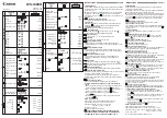
Page 8: ... 8 Audio Input Connections ...

Page 9: ...Ground Add D1 a 1 Amp general purpose diode as shown 8 Please refer to FIG 3 for audio input connections Connect the audio output from your microphone or audio processing chain to the Line In terminals 5 and 6 You can run the audio in through the rear of the transceiver using a female phono chassis mount jack or if you prefer to use the transceiver s hand mic other microphone or line out from you ...

Page 10: ...erminal to point C or D Chassis Ground 4 Run a wire from the anode of D515 FIG 2 to the Asymod III 12V input 1 terminal and connect the input 2 terminal to point C or D Chassis Ground as shown 5 Run a wire from L32 point E 12v to SW2 pin B2 as shown 6 Run the rest of the wires from SW2 to J3 and J4 as shown 7 Please refer to FIG 3 for audio input connections Connect the Audio output of your audio ...

Page 11: ... the factory When SW2 is in the DOWN position the driver and final are diverted to the Asymod III At this point the Asymod III is enabled and the mode switch must be set to AM The transceiver will only transmit on AM via the Asymod III and will be only capable to receive on FM and SSB SW2 UP stock operation SW2 DOWN Asymod III enabled ...

Page 12: ...the transceiver s chassis or heatsink with the provided hardware and before powering up Although the onboard DC DC converter can supply a maximum of 25 volts at 5 amps it is imperative to maintain the maximum carrier levels at 1 Watt for single final and 2 Watts for dual final transceivers to avoid damage However If higher carrier dead key levels are required the use of parallel or larger final mo...

Page 13: ...th the mounting hardware provided You may install T1 and T2 outside the board on the transceiver s heatsink or chassis using wire extensions Alternatively you may install T1 and T2 in parallel with more transistors of the same part number combined with 1 Ω 5W resistors as seen on FIG 5C Configuration C When using configuration C make sure to secure the board and T3 well with the mounting hardware ...

Page 14: ... 14 It is recommended to use a similar heatsink setup as seen here in FIG 5B NOTE For detailed instructions please take a look at the following link http www zen183332 zen co uk Aleph mounting PDF ...

Page 15: ...e such as a sure SM58 connected in through the transceiver s microphone jack and into the Asymod III A momentary switch also connected to the transceiver s microphone jack for PTT 5 From a stock handheld microphone with PTT built in connected in through the transceiver s microphone jack and into the Asymod III 6 From an aftermarket handheld microphone with PTT built in connected in through the tra...

Page 16: ...ency range Line Mic in for a few transceivers can be seen starting on FIG 7A Note all audio cables in the installations should be shielded FIG 7A The Cobra 29 does not have an audio input RF filter choke You may install one as shown Disconnect the wire connected to pin 2 Solder one side of L1 to pin 2 Solder a shielded wire from the other side of L1 and connect it to the Asymod Line In Make sure t...

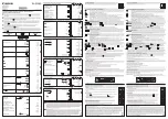
Page 17: ... 17 Installation Block Diagram Installation for Other Transceivers ...

Page 18: ...ch as the Cobra 29s 25s Galaxy DX 2547 DX 919 DX 959 etc both RF driver and RF final must be modulated to achieve maximum modulation Typically a 75 watt carrier with peaks of 10 watts produces 300 modulation levels This configuration puts a greater load on the DC DC converter as opposed to dual final transceivers where only the RF driver is modulated For dual final transceivers recommended such as...

Page 19: ... 19 The Cobra 29 and 25 installation is straight forward and easy to do simply follow the instructions in the images below Cobra 25 Fig 7G Cobra 29 Fig 7H ...

Page 20: ...insertion points TP7 and TP8 If after the installation is complete 100 modulation cannot be achieved you can try lowering the bias If that doesn t yield the results needed unsolder L40 from the TR37 emitter side and solder it to ground then unsolder L43 from the VR9 side and solder it to ground This will set the final RF stages at class C bias Basic Installation Fig 7J Advanced Installation ...

Page 21: ... the board and connect them to the DPDT switch as shown on Fig 7K connect the TP7 and TP8 board pins to the DPDT switch and finally connect the Asymod III output to the DPDT switch and board ground as seen on FIG 9 above Refer to FIG 8 for TP7 and TP8 board location Galaxy Section ...

Page 22: ... 22 Fig 9 Fig 10 ...

Page 23: ...ceivers providing the present bias and connect them to ground in the same manner as L35 and L47 in the Galaxy DX 44 as seen on Fig 11 In the case where 100 modulation cannot be achieved in any one of the Advanced Installations for multimode transceivers presented in this manual 99 9 of the time will be a bias issue In such case the bias has to be adjusted to the lowest level and if this is not suf...

Page 24: ...vers use the Ferrite Resistor combination but any of the three types in Fig 12 can be used Fig 12 To convert to class C bias simply unsolder inductors L47 L50 L35 from the resistor side at points A B C as seen on Fig 14 which is the side that should be connected to the bias circuit in this case VR11 VR20 VR10 The ferrite side should be connected to the base of the driver and final transistors Make...

Page 25: ...RF choke when applying the bias voltage to the base of the driver and final so that the RF does not pass into the DC bias circuit There are 3 types of inductors that are commonly used and they can be seen on Fig 12 1 ferrite 2 ferrite resistor combination and 3 dipped axial inductor their value should be about 22uH The ones used on the DX 949 are the dipped axial inductor 3 on Fig 12 Galaxy DX 949...

Page 26: ...ted at points A B to ground Make sure you do not unsolder L37 L33 from the side that is connected to the base of the transistors Alternatively and simpler the inductors can be completely removed from the board and installed on the bottom copper side of the board as seen done with the dipped axial type inductors on Fig 13 Fig 16 17 18 19 show basic installations with bias modification for single an...

Page 27: ...This should bring the final bias level down very close to class C if not decrease the resistor values until 100 modulation is achieved For Fig 19 Galaxy DX 98DHP Dual FET Final add a 47k resistor at the red circled points to ground This should bring the bias level down very close to class C for both finals if not decrease the resistor values until 100 modulation is achieved Fig 16 Galaxy DX 919 Si...

Page 28: ... 6PDT switch for dual final transceivers and a 4PDT switch for single final transceivers For dual final transceivers follow the connections on Fig 20 in and refer to Fig 14 for board locations Begin by unsoldering the resistor sides of L47 L50 L35 at points A B C Fig 20 6PDT switch connection for dual final transceivers For single final transceivers follow the connections on Fig 21 and refer to Fi...

Page 29: ...N general purpose transistor to in turn drive the relay Most transceivers send 8 volts out of the mode switch to activate the appropriate mode section within Find the switch terminal that provides 8 volts from the mode switch when on AM mode and use this to drive the NPN general purpose transistor to in turn drive the relay as seen on Fig 23 The mode signal varies from transceiver to transceiver s...

Page 30: ...ing a load such as a relay might damage the transceiver s mode switching circuit In such case it is recommended to always employ a transistor switch to amplify the signal to drive the relay s coil as seen on Fig 23 Outboard Potentiometer Installation Fig 24 Note The onboard trimmer variable resistors for the Modulation Level VR2 Carrier Level VR3 and Asymmetry Control VR4 increase in the countercl...

Page 31: ...r 291228536498 Before you can install the new converter you must adjust the trim pot for 25 volts Note Be sure to install the new DC DC converter the same direction seen on this image The Asymod III is equipped with convenient power supply inputs and can be connected to external supplies via the terminal solder pads under the DC DC converter or on the bottom copper side of the board as seen on Fig...

Page 32: ... 32 ...

Page 33: ... 33 ...

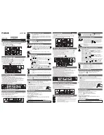
Page 34: ... 34 Asymod IIIs Stryker SR 955HPC Settings Specifications ...

Page 35: ...ryker SR 955HPC AM External Settings Optimal operating audio input levels ProTools signal generator at 1 kHz at 850 mV p p 8dBu 10dBV Voice peaks of 1 2V p p 6dBu 7dBV Line In ProTools ProTools session Stryker SR 955HPC ptf ...

Page 36: ... system The EV RE20 is highly recommended The audio path here passes through the Stryker s onboard microphone preamplifier audio high and low pass filters ANL ALC and tone circuits Although these circuits have been upgraded factory design present certain bandwidth limitations This input is intended for use when audio processing is not available via the rear Line In connector Use this input as a la...

Page 37: ...r 250 modulation 33 Watts PEP Stryker SR 955HPC W10 AM ANL Fully counter Clockwise Fig 1 Asymod IIIs Gain fully counter clockwise Level 1 3 Carrier 5 5 Asymmetry 1 6 2 5 Watt carrier 250 modulation 25 Watts PEP Stryker SR 955HPC W10 AM ANL Fully counter Clockwise Fig 1 Asymod IIIs ...

Page 38: ...tion 22 Watts PEP Stryker SR 955HPC W10 AM ANL Fully counter Clockwise Fig 1 Asymod IIIs Gain fully counter clockwise Level 1 2 Carrier 4 5 Asymmetry 1 3 1 Watt carrier 250 modulation 11 Watts PEP Stryker SR 955HPC W10 AM ANL Fully counter Clockwise Fig 1 Asymod IIIs Gain fully counter clockwise ...

Page 39: ...tion above for AM settings Microphone 600 Ohm Dynamic Note Most hand microphones have a limited frequency response to 5000 Hz which greatly defeats the purpose of a Hi Fi system The EV RE20 is highly recommended The audio path here passes through the Stryker s onboard microphone preamplifier audio high and low pass filters ANL ALC and tone circuits Although these circuits have been upgraded factor...

Page 40: ...Power 11 55 Watts Modulation 100 350 TX Bandwidth Up to 10 kHz dependent on audio process roll off AM RX Bandwidth 7 5 kHz Att Band Width 15 kHz Stop Band Att 455 100 kHz 40 dB Audio amp response 15 kHz SSB TX Peak Envelope Power 10 60 Watts TX Bandwidth Up to 7 kHz dependent on audio process roll off SSB RX Bandwidth 2 5 kHz 3dB Bandwidth 4 5 kHz Audio amp response 15 kHz ...

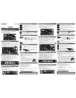
Page 41: ... 41 Asymod IIIs Cobra 2000GTL Installation eSSB Settings Specifications ...

Page 42: ... Remove R119 F and R118 G 16 Replace TR22 H with a 2N3904 invert two the right leads EBC to ECB 17 Insert one side of a 8 3kΩ resistor in R118 G lead that goes to Vcc 6V 18 Insert one side of a 10kΩ resistor in R119 F lead that goes to ground 19 Insert one side of a 100kΩ resistor in R119 lead that goes to the base of TR22 I 20 Tie together and solder together the top 3 leads of the 8 2kΩ resistor...

Page 43: ... 43 ...

Page 44: ... 44 28 Remove white wire from PA jack at Output Jack Board and solder a new wire there and run it to mic jack pin 5 ...

Page 45: ...mally closed contacts Q of the relay run another wire from the other normally closed contact R of the relay back to the place at L411 at the Phone jack Board 31 Unsolder red wire at the emitter of TR41 and connect it to the Asymod III output 32 Connect audio in coax to Asymod III Audio In Note 29 this relay has been added to allow for the receiver to be active without the microphone having to be c...

Page 46: ...ic jack Cobra 2000GTL and Asymod IIIs Settings Optimal operating audio input levels ProTools signal generator at 1 kHz at 850 mV p p 8dBu 10dBV Voice peaks of 1 2V p p 6dBu 7dBV Protools session Cobra 2000 ptf VOG 4 Aud2 4 Mbox 2 Mini Output 3 o clock Mix Fully clockwise Input At 0dB mark ...

Page 47: ...een 2 3 more toward 3 Asy 5 12 o clock position Cobra 2000 Dynamic 12 o clock position AM TX Carrier 2 Watt Modulation 250 Peak Envelope Power 16 18 Watts TX Bandwidth 10 kHz AM RX Bandwidth 7 5 kHz Att Band Width 15 kHz Stop Band Att 455 100 kHz 40 dB Audio amp response 15 kHz ...

Page 48: ... 48 SSB TX Peak Envelope Power 20 Watts TX Bandwidth 10 kHz Up to 6 7 kHz dependent on audio process roll off SSB RX Bandwidth 2 5 kHz 3dB Bandwidth 4 5 kHz Audio amp response 15 kHz ...

Page 49: ...Recording Studio app on your iOS device Audio processing for base operation is possible with the use of rack audio processing gear or computer based processing such as ProTools for PC or Mac along with the companion interface such as the Mbox 2 Mini or newer There are many choices when it comes to audio processing 1 Standalone units such as the ones found in the following link http www nu9n com tx...

Page 50: ...ons The following images show various multimode transceivers that have been equipped with the Asymod III and set to class C bias Fig 28 Galaxy Pluto Asymod III configuration B Fig 29 Galaxy Pluto Asymod III configuration B ...

Page 51: ... 51 Fig 30 Galaxy Pluto Asymod III configuration B Fig 31 Galaxy Pluto Asymod III configuration B ...

Page 52: ... 52 Fig 32 Galaxy Pluto Asymod III configuration B Fig 33 Galaxy DX 77HML Asymod III configuration C ...

Page 53: ... 53 Fig 34 Galaxy DX 77HML Asymod III configuration C Fig 35 Galaxy DX 77HML Asymod III configuration C ...

Page 54: ... 54 Fig 36 RCI Ranger 2950 Asymod III configuration C Fig 37 RCI Ranger 2950 Asymod III configuration C ...

Page 55: ... 55 Fig 38 RCI Ranger 2950 Asymod III configuration C Fig 39 RCI Ranger 2950 Asymod III configuration C ...

Page 56: ... IIIs Mounting Hardware Customer support asyadvice gmail com Asymod products are available at www bxc mobi Asymod is a registered trademark and may not be reproduced or used by any means or in any form whatsoever ...

Page 57: ... 57 ...

Reviews: