2
3
4
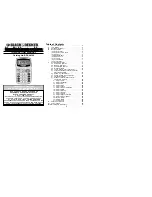
SETUP GUIDE FOR
«MCP-400» MODULATORS
USING THE SPI-300 PROGRAMMING UNIT
+12V
HPA-120
BROADBAND AMPLIFIER
INPUT
OUTPUT
GAIN
Ref. 4426
47-862 MHz
EXT INPUT
OUTPUT TEST
-30 dB
Gain 6 dB
-20 dB
ON
INPUT TEST
VIDEO
CONTROL
STATUS
+12V
MCP-411
TV MODULATOR
RF OUT
AUDIO
L
(Mono)
R
VIDEO
CONTROL
STATUS
+12V
MCP-411
TV MODULATOR
RF OUT
AUDIO
L
(Mono)
R
CFP-700
POWER
+24V
+18V
300 mA
(22 KHz)
+12V
5A
+13V
300 mA
(22 KHz)
+18V
300 mA
+13V
300 mA
:700 mA
I
TOT (MAX)
VIDEO
CONTROL
STATUS
+12V
MCP-400
TV MODULATOR
RF OUT
AUDIO
L
(Mono)
R
TV SYSTEM
VIDEO
CONTROL
STATUS
+12V
MCP-400
TV MODULATOR
RF OUT
AUDIO
L
(Mono)
R
TV SYSTEM
VIDEO
CONTROL
STATUS
+12V
MCP-411
TV MODULATOR
RF OUT
AUDIO
L
(Mono)
R
VIDEO
CONTROL
STATUS
+12V
MCP-400
TV MODULATOR
RF OUT
AUDIO
L
(Mono)
R
TV SYSTEM
VIDEO
CONTROL
STATUS
+12V
MCP-411
TV MODULATOR
RF OUT
AUDIO
L
(Mono)
R
VIDEO
CONTROL
STATUS
+12V
MCP-411
TV MODULATOR
RF OUT
AUDIO
L
(Mono)
R
1
2
3
4
5
6
7
8
9
C
0
SPI-300
GB
Programming the MCP-400 Modulators
Programming the MCP-400 Modulators
Index
1. The Start Screens
1.1 - Module Basic Information ...................................................... 3
1.2 - Main Menus .......................................................................... 4
2. The Setting Screens
2.1 - The RF Screen ............................................................ 5 / 6 / 7
2.2 - The Video Screen ................................................................ 7
2.3 - The Audio Screen .................................................................. 8
3. The Information Screens
3.1 - The Alarms Screen ................................................................ 9
3.2 - The Details Screen ................................................................ 9
4. The Divers Screens
4.1 - The Configurations Screen ................................................. 10
1.2 - Main Menus
As explained in the Basic Handling guide, the
General
menu is identical for all the
modules and its contents was described on page 8. The
Settings
and
Info
menus
include, however, options and information which are peculiar to each type of module.
Those of the MCP modulators are the following:
-
Settings
Menu : Contains all the setting parameters of the connected modulator,
grouped by sections which are displayed on one or several screens. There are
three sections :
●
RF
: You must select it to set the parameter values related to the RF output
signal of the modulator.
●
Video
: Allows to select the available video options.
●
Audio
: Idem, the audio options.
-
Info
Menu: Allows to get access to detailled information about the funtionning of
the module, further on the one provided by the basic information screen (see
previous page). Information is distributed in two screens, each one related to a
menu option:
●
Alarms :
Informs whether the module has some alarm activated and its type.
●
Details :
Identifies the module and displays outstanding data.
1
!
Alarms
2
Details
ESC
SEL
1
!
RF
2
Video
3
Audio
ESC
SEL
1
1. THE START SCREENS
1.1 - Module Basic Information
As explained in the Basic Handling guide supplied with the SPI-300, when you
connect this to the module all data for identification, configuration and status of the
module are loaded on the SPI-300. A detection screen appears for a short time, and
next the display shows the Basic Information screen, which identifies the module and
presents its most representative configuration and status data.
MCP-422
Alarm:No
F01.02
Audio:Stereo
TVSys:DK
Out.Freq.: 687.25
OK
The basic information screen for the MCP-400 modulators is the following :
These are the meanings of the expressions and data displayed :
- Name of the module.
- "F-.-" : Version of the firmware (the firmware is the software stored in the module
that manages its basic running).
- "Output Frequency" : Is the video carrier of the output TV channel, in MHz.
- "Alarm" : Informs about the existence or not of module working failures.
- "Audio" : Displays the Audio Mode (mono, stereo, dual) that is selected in the
modulator.
- "TV System" : Is the TV system (fixed or selected) of the output TV channel.
The screen closes using the OK command (key ). Then the Main Menu Screen
appears (page 8 of the Basic Handling guide).