ASV RC-100, Service Manual
The Roland RC-100, a versatile audio playback device, comes with a comprehensive user manual to ensure hassle-free operation. Our website provides a free and quick manual download for this remarkable product, offering clear instructions and technical insights. Discover the RC-100's immense potential by downloading the manual from manualshive.com.
Share
Download


Reviews:
No comments
Related manuals for RC-100
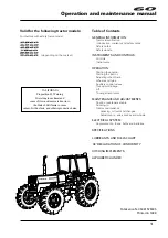
5860
Brand: LANDINI Pages: 132
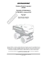
LP8500
Brand: Dynapac Pages: 34

HORTUS HS CL
Brand: Zetor Pages: 142

TX1500
Brand: TYM Pages: 218

R3 EVO 85
Brand: LAMBORGHINI Pages: 61
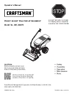
486.248476
Brand: Craftsman Pages: 24

917.99039
Brand: Craftsman Pages: 36

917.257571
Brand: Craftsman Pages: 28
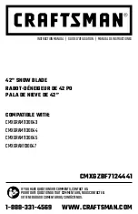
CMXGZBF7124441
Brand: Craftsman Pages: 36
917.203930
Brand: Craftsman Pages: 72
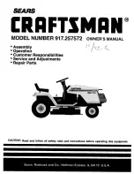
917.257572
Brand: Craftsman Pages: 28

Aster 35
Brand: GOLDONI Pages: 76

Elite 15XEBL
Brand: Broan Pages: 44

T1
Brand: townew Pages: 8

Teleporter
Brand: Sanderson Pages: 17

4KUCS181T
Brand: KitchenAid Pages: 39

DK752C
Brand: Daedong Pages: 12

TeeJet Matrix 908
Brand: Spraying Systems Pages: 40


