ASTRO ATS-9900, Operator'S Manual
The ASTRO ATS-9900 Operator's Manual is your comprehensive guide to harnessing the full potential of this advanced product. Find and download the manual for free on our website, ensuring optimal usage of the ASTRO ATS-9900. Unlock its features and maximize efficiency with our easy-to-follow manual.
Share
Download


Reviews:
No comments
Related manuals for ATS-9900
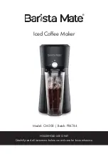
CM300
Brand: Barista Mate Pages: 12

49980
Brand: Hamilton Beach Pages: 44

40715
Brand: Hamilton Beach Pages: 44

40400
Brand: Hamilton Beach Pages: 28

Bar Italia ESP2
Brand: Breville Pages: 8

ES-180
Brand: Rowenta Pages: 60

CM01X
Brand: Kleenmaid Pages: 36

NESPRESSO PIXIE M 112
Brand: MAGIMIX Pages: 33

CLASSE 10
Brand: Rancilio Pages: 41

00111274
Brand: Xavax Pages: 40

Caf 3 in 1 Coffee Maker KDC120
Brand: Kambrook Pages: 10

JG 3518
Brand: SEVERIN Pages: 76

49464 - Programmable Coffee Maker
Brand: Hamilton Beach Pages: 2
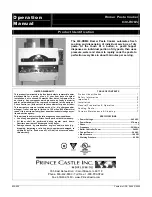
630-ROM4
Brand: Prince Castle Pages: 9

011705
Brand: Menuett Pages: 16

PANETTI AR 2017
Brand: Arzum Pages: 76

H5E
Brand: Bunn Pages: 2
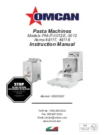
49117
Brand: Omcan Pages: 24


