manualshive.com logo in svg
background image


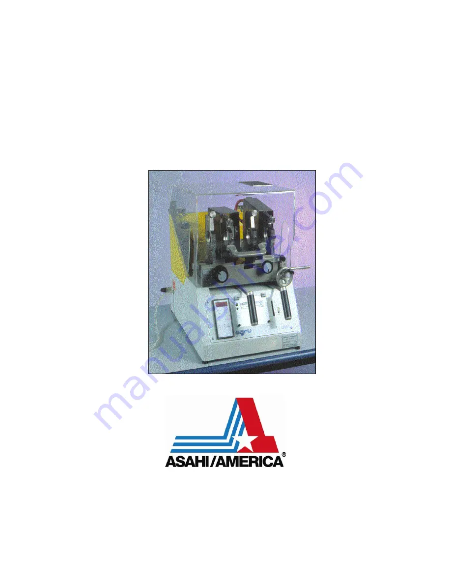
Proweld™ Equipment Manual 


UF2000/1


35 Green Street, PO Box 653, Malden, MA 02148 

Tel: (781) 321-5409 - Fax: (781) 321-4421 Toll Free: (800) 343-3618 

www.asahi-america.com – [email protected] 

Direct Sales: East (800) 232-7244  


Содержание Proweld UF2000/1

Страница 1: ...eld Equipment Manual UF2000 1 35 Green Street PO Box 653 Malden MA 02148 Tel 781 321 5409 Fax 781 321 4421 Toll Free 800 343 3618 www asahi america com asahi asahi america com Direct Sales East 800 232 7244 ...

Страница 2: ...TABLE OF CONTENTS SECTION I Training overview on the UF2000 1 Series Equipment SECTION II Operation and Welding Concerns SECTION II Inspection Procedures Asahi America Inc UF 2000 1 Page 2 of 18 ...

Страница 3: ...e the carriage close together to avoid a long projecting length of the rack from the machine b Relieve back run safety device so that no pressure presses on the compressing spring and thus the load cell in the internal of the machine c Put the included set collar over the projecting rack d Fix the set collar sturdy with the adjusting screw concisely to the machine frame e Secure the position lever...

Страница 4: ... pipe size the respective clamping devices should be screwed to the clamp tools j With non contact welding the distance between the end of the pipe and the heating element must be 1mm This can be tested with the help of the included reference gauge If necessary adjust the distance screws at the heating element Important Before switching on the machine if the heating elements for butt welding or te...

Страница 5: ...digits joint no automatic count time date set time and date Welding parameters by material diameter and wall thickness are on page 6 Also enclosed is a cut sheet which can be checked off and attached to each tool 5 Welding method UF2000 1 Quick Review pl Planing al Alignment t A Increase pressure against heating element t Aw Heat soak time the heating time pipe together t U Adjustment time Time al...

Страница 6: ...5mm 150psi 4 110mm 3 0mm liner 2 63mm 3 0mm 230psi 4 110mm 3 5mm 150psi 2 63mm 3 6mm 300psi 4 110mm 5 3mm 230psi 4 110mm 6 3mm 300psi 4 125mm 3 0mm liner 4 125mm 3 9mm 150psi 4 125mm 6 1mm 230psi 5 140mm 4 4mm 150psi 5 140mm 6 7mm 230psi 6 160mm 3 0mm liner 6 160mm 4 9mm 150psi 6 160mm 7 7mm 230psi 7 180mm 5 6mm 150psi 7 180mm 8 7mm 230psi 8 200mm 6 2mm 150psi 9 225mm 7 1mm 150psi 9 225mm 10 9mm 2...

Страница 7: ... and or joining pressure out of tolerance Error 5 Cooling time too short Error 6 During cool down period the joining pressure is out of tolerance Error 7 Capacity of welding data is exhausted Error 8 1990 welds complete unit may need to be returned for routine maintenance Only displayed when cycling tool on off Error 9 2200 welds complete unit should be returned for routine maintenance Only displa...

Страница 8: ...3 3 4 32x3 0 1 10 150 450 40 3 3 5 40x3 7 1 1 4 10 150 450 45 3 3 6 50x4 6 1 1 2 10 150 450 50 3 4 7 63x5 8 2 10 150 450 60 3 4 8 IR Fusion Parameters for E CTFE These welding parameters are valid at 20 C 68 F gap1mm Dimension PN Temperature Pre Heating Adjusting Joining Cooling mm inch bar psi C Time sec Time sec Time sec Time min 20xl 9 1 2 20 284 480 50 3 3 2 25xl 9 3 4 20 284 480 55 3 3 2 32x2...

Страница 9: ...d after the joint has been made This problem may be from attempting to preheat the pipe or from welding with incorrect parameters Solution It is not recommended to preheat pipe The tool automatically compensates for the outside temperature If there is a significant amount of air flow preheating will not overcome the flow of air It is preferred to move the tool or protect it in some fashion against...

Страница 10: ...is not possible to turn the fitting on its side then caps with perforation should be utilized Common Concern 4 Burnt Joint If a joint appears discolored under light it may be slightly burned The burning is normally caused by insufficient planing or incorrect welding temperature Solution Each time a joint is conducted the pipe end must be planed to the mechanical stop on the planer Insufficient pla...

Страница 11: ...VDF and Halar only When welding with PolyPro the uniformity is the same for pipe as it is for pipe to fitting Pipe to Pipe Very uniform and equal on both sides Pipe to Fitting Uniform but the fitting bead is normally slightly larger Fitting to Fitting Very uniform but larger in general compared to pipe to pipe Top versus Bottom Due to the natural effects of gravity the bead externally will appear ...

Страница 12: ...nds This will help to verify the heat temperature and welding parameters 2 After the heat soak time is complete when making a joint and the pipe is rejoined together a narrow object such as a pencil or finger can be placed inside the pipe without touching the joint The operator should be able to see through the molten material for a few seconds and see the object This will verify the welding press...

Страница 13: ...o operate incorrectly this is easily identified by the error numbers on the weld label All joints with printed error numbers are recommended to be cut and redone 2 Air Movement In addition to the weld label visual inspection can assist in limiting the likelihood of a failure The UF2000 equipment can control the majority of mistakes that can be made during the fusion but it does have limitations su...

Страница 14: ...nt that has been heated improperly or what we will call incomplete fusion is possible to identify by inspection The signs of a joint heated insufficiently are 1 Decreased bead size in certain sections of the joint 2 Decreased bead size all around as compared to other joints of the same size 3 No bead formation in a section of the weld These occurrences are generally from 1 air movement 2 Incorrect...

Страница 15: ...omputer utilizing the Wicon software that is included in each unit The data transferred from each weld provides an inspector with more information about the weld than what appears on the printout label Below is an example of the data AGRU UF 2000 1 Serial No 1293005 date 02 09 96 10 58 ident key AA01 proj no 1265 joint no 405 dia 63mm wth 3 0mm mat PVDF nitro pres 0 0bar method IR amb temp 21 C de...

Страница 16: ...able for storage Press the enter key four times to scroll out of the command 30 2 The Data Transfer a Connect the communication cable to the tool and the PC comport b On the PC open the Wicon program and select file window and click on the command dtf data transfer The PC screen will display in incorrect grammar please wait wile I read data c On the UF Tool now press and enter key simultaneously T...

Страница 17: ...eously and the tool screen will display 0000 b Enter in 0030 c The screen will now display the amount of available storage left on the unit Enter in 0001 and press enter d The memory is now deleted To double check enter in command 0030 again and the amount of available storage should be 1101 or 1100 indicating the memory is completely empty Asahi America Inc UF 2000 1 Page 17 of 18 ...

Страница 18: ...america com asahi asahi america com Equipment Rental Rental Equipment Manager 781 388 4618 toolmanager asahi america com Rental Administration Billing Returns 781 388 4623 toolrental asahi america com Field Technician Onsight Training 617 480 7071 info asahi america com Technical Service High Purity Double Wall or Industrial Piping 781 321 5409 pipe asahi america com ...

Отзывы: