background image

Rev. 0040501006 3814 englisch

1.0 General information on operating instructions............................................................................................. 2-3
2.0 Notes on possible dangers ............................................................................................................................. 2-3

2.1  Significance of symbols  ........................................................................................................................... 2-3
2.2  Explanatory notes on safety information................................................................................................... 2-4

3.0 Storage and transport ..................................................................................................................................... 2-4
4.0 Description ....................................................................................................................................................... 2-5

4.1  Field of application .................................................................................................................................... 2-5
4.2  Method of functioning................................................................................................................................ 2-5
4.3  Diagram .................................................................................................................................................... 2-6

4.3.1 ARI-PREMIO®-Plus 2G 2,2 - 5 kN .................................................................................................. 2-6
4.3.2 ARI-PREMIO®-Plus 2G 12 - 15 kN ................................................................................................. 2-7
4.3.3 Parts list ........................................................................................................................................... 2-8

4.4  Technical data ........................................................................................................................................... 2-9
4.5  Interface description.................................................................................................................................2-11

4.5.1 Control - Run commands  ...............................................................................................................2-11
4.5.2 Feedback   ..................................................................................................................................... 2-12
4.5.3 Design notes.................................................................................................................................. 2-13

4.5.3.1 Control signal ......................................................................................................................................2-13
4.5.3.2 Behavior in control signal failure / error...............................................................................................2-14
4.5.3.3 Analogue feedback signal ...................................................................................................................2-15
4.5.3.4 dTRON 316 .........................................................................................................................................2-15

4.6  Dimensions ............................................................................................................................................. 2-16

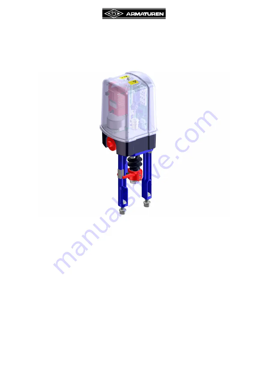
Operating and Installation Instructions


Thrust actuator 

ARI-PREMIO

®

-Plus 2G

Inhaltsverzeichnis

Summary of Contents for ARI-PREMIO-Plus 2G

Page 1: ...2 5 4 3 Diagram 2 6 4 3 1 ARI PREMIO Plus 2G 2 2 5 kN 2 6 4 3 2 ARI PREMIO Plus 2G 12 15 kN 2 7 4 3 3 Parts list 2 8 4 4 Technical data 2 9 4 5 Interface description 2 11 4 5 1 Control Run commands 2 11 4 5 2 Feedback 2 12 4 5 3 Design notes 2 13 4 5 3 1 Control signal 2 13 4 5 3 2 Behavior in control signal failure error 2 14 4 5 3 3 Analogue feedback signal 2 15 4 5 3 4 dTRON 316 2 15 4 6 Dimens...

Page 2: ...point input 2 33 5 6 6 Priorities 2 33 5 7 Options 2 34 5 7 1 Relay card 2 34 5 7 1 1 Operating principle 2 34 5 7 1 2 Technical data 2 35 5 7 1 3 Installation procedure 2 35 5 7 1 4 Electrical connection 2 35 5 7 1 5 Operation Programming clearing positions 2 36 5 7 2 Analogue output card Yout 2 37 5 7 2 1 Operating principle 2 37 5 7 2 2 Technical data 2 37 5 7 2 3 Installation procedure 2 38 5 ...

Page 3: ...to monitor the personnel In addition current regional safety requirements must be applied and observed when taking the fittings out of service as well as when maintaining and repairing them The manufacturer reserves the right to introduce technical modifications at any time These Operating Instructions comply with the requirements of EU Directives 2 0 Notes on possible dangers 2 1 Significance of ...

Page 4: ...s well as technical data in the operating instructions product documentation and on the device itself must also be complied with to the fullest extent in order to avoid faults which in turn can cause serious injury to persons or damage to property 3 0 Storage and transport At 40 C to 85 C dry free from dirt Do not unpack thrust drive or setting equipment assembly prior to installation Protect agai...

Page 5: ...y the electronics in an initialization run An analogue signal must be present at the input during the initialization run for analogue control The desired position can be specified by means of the analogue control input The input is protected against polarity reversal It can be configured as a current 4 to 20 mA or voltage 0 to 10 V input using a switch Two binary control inputs are provided for th...

Page 6: ...Page 2 6 0040501006 3814 Operating and installation instructions Thrust actuator ARI PREMIO Plus 2G 4 3 Diagram 4 3 1 ARI PREMIO Plus 2G 2 2 5 kN Fig 1 Yoke Version Column Version ...

Page 7: ...0040501006 3814 Page 2 7 Operating and installation instructions Thrust actuator ARI PREMIO Plus 2G 4 3 2 ARI PREMIO Plus 2G 12 15 kN Fig 2 ...

Page 8: ... 127 Washer ISO 7093 1 50 18 Hexagon head screw DIN EN ISO 4017 M10x55 50 128 Sealing nut Seal lock M6 50 19 T head bolt DIN 261 M12x40 50 139 Protective cover 50 20 Washer DIN EN ISO 7089 50 140 Switch cover 50 21 Spring washer DIN 128 A12 50 141 Trip slide 50 22 Hexagon nut DIN EN ISO 4032 M12 50 142 Shakeproof washer 50 23 Lift dial 50 143 Connector 2 pole N L 50 24 Distance column 50 144 Conne...

Page 9: ...Enclosure EN 60529 IP 65 Max storage temperature 40 C 85 C Max permissible ambient temperature 20 C 70 C For outdoor use and sub zero temperatures a heating is recommended Hand operating device Yes always running Yes engageable Operation optional 3 point 12V AC DC to 250V AC DC 0 to 10V DC load resistance 500 kOhm resolution 12Bit 4 to 20mA DC load resistance 125 Ohm resolution 12Bit Max cable cro...

Page 10: ...AC 24V AC DC 15W automatic switching circuit Potentiometer Conductive max 2 pcs 1000 2000 5000 Ohm 1 Watt bei 70 C Schleiferstrom max 0 01mA empfohlen 0 002mA Wire max 2 pcs 100 200 Ohm 0 5 Watt at 70 C Wiper current max 35mA recommended 0 02mA Process controller Type Processcontroller dTRON 316 Mounted in the actuator 4 20mA output for operation of ARI PREMIO Plus 2G for resistance thermometers a...

Page 11: ...isolated Modbus Protocol Modbus Modbus integer Baud rate 9600 19200 38400 Device address 0 255 Max number of participants 32 dTRON316 with analogue output card and RS422 485 card dTRON options Profibus DP Device address 0 255 dTRON316 with analogue output card and Profibus card dTRON options Sollwert Ansteuerung für PID Prozessregler Option dTRON 316 4 20mA DC Burden 75 Ohm Resolution 10Bit dTRON3...

Page 12: ... Relay card ARI PREMIO Plus 2G Modbus Protocol Modbus Modbus integer Baud rate 9600 19200 38400 Device address 0 255 Max number of participants 32 Relay card ARI PREMIO Plus 2G dTRON 316 with RS422 485 card and at more than 2 binary feedbacks the binary input card is required dTRON options Profibus DP Device address 0 255 Relay card ARI PREMIO Plus 2G dTRON 316 with Profibus card and at more than ...

Page 13: ...rol in direction OPEN and CLOSED over the 3 point control signal the motor stops so that the drive no longer follows the analogue input signal The switch positions for control signal type and inversion affects to the analogue input and feedback signal There are no separate settings for the input and feedback signal possible Warning signal Manual operating device Blockage detected Position cannot b...

Page 14: ...e older software versions at values between 0 101 the slide switch sets three different actuator characteristics that define the relationship between the input signal and the valve position For a linear relationship please set this switch to the lowest position Inverse equal percentage Equal percentage Linear The characteristic correction function allows you to adjust the effective characteristic ...

Page 15: ...tput signal can be larger than in the normal control range The deviation is from the actuator and valve travel dependent By CDF management the duty cycle of the motor is reduced to prevent an overheating This allows the differences between the control signal and feedback will be greater 4 5 3 4 dTRON 316 Standard inputs and outputs dTRON 316 A maximum of 2 optional cards for the dTRON 316 are poss...

Page 16: ...6 SW mm 17 X mm 150 H mm 447 480 h Nominal stroke mm max 30 max 50 ARI PREMIO Plus 2G 2 2 5 kN Nominal stroke max 30 mm ARI PREMIO Plus 2G 2 2 5 kN Nominal stroke 30 mm 50 mm ARI PREMIO Plus 2G 12 15 kN Nominal stroke max 65 mm 12 15 kN A mm 210 B mm 184 C mm 90 ØD1 mm 130 X mm 200 H mm 622 637 h Nominal stroke mm max 50 max 65 L Column mm 234 249 ...

Page 17: ...where there is protection against high energy heat radiation Thrust actuator mountable in any position except in downward suspended position If installed with a horizontal connecting rod the thrust actuator must be mounted so both yoke legs or columns are on top of one another in the vertical plane see Fig 6 Fig 6 ATTENTION Work on electrical systems or equipment must only be carried out by qualif...

Page 18: ...y original spares The following must be provided Complete valve with crossbar and Operating Instructions The valve plug must be approximately in the mid lift position never in contact with a seat Thrust actuator complete with yoke or distance columns and coupling parts intended for mounting to the corresponding valve In case of widely fluctuating ambient temperatures high atmospheric humidity and ...

Page 19: ...he manual operating device always rotates during motor driven operation running indicator Never activate the manual operating device while the motor is running Injury hazard In the manual operating mode pay careful attention in the final positions that the manual operating device is only turned to the point where the torque switch trips audible click as otherwise damage will be caused to the thrus...

Page 20: ...A B Slip coupling pos 50 27 over valve stem Screw threaded bush pos 50 87 matching the valve onto the valve stem in accordance with setting dimension Y and lock with hexagon nut Setting dimension Y for fitting projection X 60 and 83mm 102mm Fig 9 B Hexagon nut Valve stem ATTENTION X 60 83mm Y 102mm 2mm X 98mm Y 116mm 2mm ATTENTION Setting dimension Y and fitting projection X are measured with inse...

Page 21: ...nd use it to move out the thrust actuator until the driving spindle pos 50 30 comes to rest on the threaded bush pos 50 87 Fig 9 F Fig 9 F Screw the coupling pos 50 27 firmly into the torsion safety feature pos 50 32 and secure in place using grub screw M6 pos 50 35 Run valve to lowest position Clip lift dial pos 50 23 onto yoke in such a way that top edge of torsion safety feature is in alignment...

Page 22: ... threaded bush pos 50 87 matching the valve onto the valve stem in accordance with setting dimension Y and lock with hexagon nut Setting dimension Y for fitting projection X 83mm 102mm Setting dimension Y for fitting projection X 98mm 116mm Fig 10 B Hexagon nut Valve stem ATTENTION X 60 83mm Y 102mm 2mm X 98mm Y 116mm 2mm ATTENTION Setting dimension Y and fitting projection X are measured with ins...

Page 23: ...ng button for manual mode button engages Having done this move out the thrust actuator until driving spindle pos 50 30 comes into contact with threaded bush pos 50 87 refer to point 5 2 2 ARI PREMIO Plus 2G 12 15 kN Fig 8 Fig 10 F Fig 10 F Screw coupling pos 50 27 firmly into torsion safety feature pos 50 32 and secure using grub screw M6 Pos 50 35 Move the valve to the lowest position Press 2 ear...

Page 24: ...dle FÜ Groove for trip slides ARI PREMIO Plus 2G 2 2 5 kN ARI PREMIO Plus 2G 12 and 15 kN Corresponding to the actuator type lock the trip slide in the groove Fig 11 A Corresponding to the fitting projection X lock the trip slide in the groove Fig 11 B 1 2 2 kN Yoke version z 57 mm 1 2 2 2 kN Column version and 5 kN z 53 mm 1 1 X 60 83 mm z 74 0 5 2 X 98 mm z 74 0 5 ...

Page 25: ... closed open A AB open B AB open AB B open AB A open Straight through valve 3 way valve with diverting plug 3 way valve with mixing plug Wire connections of the different valve types Option 90V 264V AC Power red blue HZ Heating resistor TTR Electronic temperature controller dTRON 316 see page 26 Relay Relay board Y out Analogue output card POT Potentiometer ARI PREMIO Plus 2G Standard 24V AC DC ...

Page 26: ... Wiring diagram ARI PREMIO Plus 2G 2 2 15 kN dTRON316 Fig 13 Accessories frei Resistance thermometer Resistance transmitter Thermo couples Current 0 4 20mA Voltage 0 2 10V power 230V 3A Binary output Out1 230V 3A Binary output Out2 2 contacts of the relay card for error warning or positioning feedback upply ...

Page 27: ...icians or by trained individuals under the guidance and supervision of a qualified electrician in compliance with regional electrical requirement and regulations When connecting the electronics the supply line must be disconnected from the mains not live during connection work It must be impossible to switch the power on unintentionally while the mains are disconnected in this way Failure to compl...

Page 28: ...rations or lack of care may cause death grievous bodily injury or substantial property damage Operation of the thrust actuator without the hood for any purpose other than that described above is strictly prohibited LEDs for status information Rpm operating speed adjustment RPM rounds per minute Local operation of the actuator Up stop down Auto The actuator follows the control signals Led s blinkin...

Page 29: ...ware and restores the factory settings Any faults that are stored are cleared blockage etc If you press the Reset button for longer than two seconds the actuator control starts an initialization run The yellow Out of specification LED blinks as long as the initialization run is active The actuator automatically travels to the two final positions in order to determine the valve lift You can cancel ...

Page 30: ...N Force off The Force switch specifies the direction in which the actuator is switched off by the thrust in the final position Switch up Retracting spindle Mid position Both directions Switch down Extending spindle The tight closing function is active in the set final position s to ensure that the valve is closed with the nominal actuator force The function is activated within a capture range equi...

Page 31: ...e LED is set Anti Block Off The retraction algorithm is deactivated The orange LED is set if a blockage occurs Economy wear reduction program The wear on the valve and actuator mechanism can be reduced to a minimum by implementing various protective measures to extend the lifetime Economy On This operating mode affords maximum protection for the valve and actuator mechanism as follows Adaptive hys...

Page 32: ...ide the hysteresis band If the actuator signal changes direction more than six times in one minute because all deviations of the desired position were outside the current hysteresis band the band is widened and the next larger step set There are six possible hysteresis steps If the actuator specifies fewer than two direction changes within one minute the next lower step is set 5 6 2 Temperature ma...

Page 33: ...ctronics both 4 to 20 mA and 0 to 10 V If the control signal fails for longer than ten seconds the red Failure LED is set and the actuator is switched to Stop As soon as a control signal is detected at the input again for longer than ten seconds the red LED goes out and the actuator returns to the desired position 5 6 5 Double control at the 3 point input The 3 point control signal takes priority ...

Page 34: ...cal options While these operations are in progress the thrust actuator has hazardous live uninsulated parts exposed as well as moving and rotating parts Improper execution of the setting operations or lack of care may cause death grievous bodily injury or substantial property damage Operation of the thrust actuator without the hood for any purpose other than that described above is strictly prohib...

Page 35: ...occurs for instance A blockage additionally results in a Failure signal because the desired position cannot be reached 5 7 1 2 Technical data 5 7 1 3 Installation procedure 5 7 1 4 Electrical connection Fig 19 Type Relay 1 Position 2 Position 3 Warning 4 Failure Switching capacity UB 250V 6A inductive load 3A ohm resistive load 30V AC DC 2A Type Floating changeover contacts Max conductor cross sec...

Page 36: ...s Relay 2 button down until the corresponding LED blinks once From now on relay 2 is switched to active when the current position is overtravelled in the DOWN direction Clear Press Relay 1 button up AND Relay 2 button down simultaneously for longer than one second Both LEDs blink once to confirm the new setting From now on the two relays are no longer switched Overwrite Similar to Prog Rel 1 or Pr...

Page 37: ...ed on the motherboard The feedback signal 4 to 20 mA 0 to 10 V or inverted corresponds to the switch configuration on the motherboard The characteristic correction function has no effect on the output signal 5 7 2 2 Technical data Pcs Designation 1 Analogue output card 2 PT screws Fig 21 Type Analogue output card Yout Output control signal YU 0 10V DC Measuring resistance load max 2 kohm Signal re...

Page 38: ...Page 2 38 0040501006 3814 Operating and installation instructions Thrust actuator ARI PREMIO Plus 2G 5 7 2 3 Installation procedure 5 7 2 4 Electrical connection Fig 24 Fig 22 Fig 23 ...

Page 39: ...xagon screw on the hood remove carefully hood Using the supplied screws mount complete heating on holding bracket at the point on the gearbox cover plate provided for the purpose Fig 25 Lead continuous current cable mains voltage rated voltage of heating through cable inlet into thrust actuator and fix in place with inlet Strip continuous current cable approx 1 1 5 cm above cable inlet Strip indiv...

Page 40: ...he dTRON 316 can be mounted in the ARI PREMIO Plus 2G as a complete unit with a mounting kit To install the dTRON 316 proceed as follows In addition to 5 4 Electrical connection the electrical connection of the dTRON 316 has to be done in the following way Mount the temperature controller on the gear plate by using the specific installation kit Fig 27 Plug in the connector X25 of the dTRON 316 to ...

Page 41: ...lus 2G Fig 27 Installation dTRON 316 ARI PREMIO Plus 2G 2 2 5 kN Pos Benennung 50 81 Head cap screw DIN EN ISO 4762 M4x8 50 97 Temperature controller dTRON 316 50 98 Fixing bracket Option dTRON 50 99 Holding bracket Option dTRON 50 100 Self locking nut Option dTRON 50 97 50 99 50 100 50 98 50 81 ...

Page 42: ...logue input control signal is present the parameter switch must additionally be set for 0 to 10 V or 4 to 20 mA on the operator panel ATTENTION All local safety instructions must be observed Before putting a new plant into operation or restarting a plant after repair or modification always make sure that The power supply control signal and ambient temperature coincide with the technical data of th...

Page 43: ...ed and set for this purpose refer to 6 1 Configuring the control signal You can start an initialization run in any operating mode by pressing the Reset button for longer than two seconds The yellow Out of specification LED blinks when the initialization run is active The actuator automatically travels to the two final positions in order to determine the valve lift You can cancel the initialization...

Page 44: ...g agent to clean the actuator rather than applying it directly 8 0 Troubleshooting In the event of malfunction or faulty operating performance check that the installation and adjustment work has been carried out and completed in accordance with these Operating Instructions If malfunctions cannot be eliminate with the help of the following table 9 0 Troubleshooting table the supplier or manufacture...

Page 45: ...ARI PREMIO Plus 2G electronics have no power Check the power supply to the electronics Initialization cancelled red and yellow LEDs lit Outside the valid travel range Possible causes Incorrect fitting projection incorrect column length valve missing Red LED lit Actuator not initialized yet Start an initialization run after mounting the actuator on a valve and connecting the control signal No value...

Page 46: ...nt to main lines Use shielded cables for the control signal Connect a 100 µF to 470 µF capacitor parallel to the signal input There is AC voltage approx 8 5 V for a 0 V control signal at the signal input if a common ground is used for the control signal and the 24 VAC power supply three wire This could be due to a wiring error in the 24 VAC power supply for the signal source e g controller Check t...

Page 47: ... and process influences CDF exceeded Max hysteresis Supply voltage frequency out of tolerance Toleranzen Overheating Moisture Heating has been on for longer than 1 h Function check Orange Configuration change local operation substitute value Manual mode local operation The actuator is controlled by the handwheel or locally Blockage detected Failure Red Internal failure Process failure Yin interrup...

Page 48: ...ove thrust actuator from valve No initialization run Green Red Blockage Green Red Orange Yin control signal failure Green Red Yellow ADV outside the travel path Green Red Orange Yellow Position kann nicht erreicht werden Green Red Orange Blue Position can not be achieved Green Red Orange Yellow Blue Motor error Green Red Blue ATTENTION The supply line for connecting up the thrust actuator must be ...

Page 49: ...r conditions deviating from those laid down by specifications or other agreements Justified complaints will be eliminated by repair carried out by us or by a specialist appointed by us No claims will be accepted beyond the scope of this warranty The right to replacement delivery is excluded The warranty shall not cover maintenance work installation of external parts design modifications or natural...

Page 50: ...ert Richter GmbH Co KG Mergelheide 56 60 33756 Schloß Holte Stukenbrock that the supplied model of thrust actuator ARI PREMIO Plus 2G in the delivered version complies with the following regulations EC Directive about electromagnetic compatibility 2004 108 EG Applied harmonized standards DIN EN 61000 6 1 3 DIN EN 61000 6 2 4 EG Low voltage directive 2006 95 EG Applied harmonized standards EN 60204...

Page 51: ...0040501006 3814 Page 2 51 Operating and installation instructions Thrust actuator ARI PREMIO Plus 2G ...

Page 52: ...0040501006 3814 Page 2 52 Operating and installation instructions Thrust actuator ARI PREMIO Plus 2G ...

Reviews: