background image


An Arcadian Networks Inc. Technical Document 

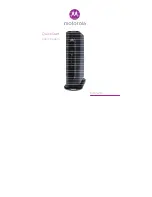
V487


W

IRELESS 

M

ODEM 

U

NIT


User’s Guide


Version: 

113


P/N: 

3BR0035


Summary of Contents for V487

Page 1: ...An Arcadian Networks Inc Technical Document V487 WIRELESS MODEM UNIT User s Guide Version 113 P N 3BR0035...

Page 2: ...cifically incorporated by reference into such contract or warranty The information contained herein is merely descriptive in nature and does not constitute a binding offer for the sale of the product...

Page 3: ...enerates uses and can radiate radio frequency energy and if not installed and used in accordance with the instruction manual may cause harmful interference to radio communications Operation of this eq...

Page 4: ...quirements L quipement sous tension doit tre branch a une source limit e au maximum de100 VA conform ment a UL 60950 1 5 Voltage rating is from 9 5VDC to Maximum 29VDC La tension d op ration est de 9...

Page 5: ...e Secure all power cabling when installing this unit Do not touch the power supply when the power cord is connected Line voltages are present within the power supply even when the power switch is off...

Page 6: ...Target Audience 7 1 3 Document Conventions 8 1 4 Arcadian Networks 8 2 Modem Features and Components 9 2 1 Right Panel Indicators 9 2 2 Left Panel Connectors 10 3 Using the Modem 11 4 Technical Specif...

Page 7: ...User s Guide This guide is designed to be used as a tool in the initial installation and periodic maintenance of the V487 It contains information on how to perform the following tasks Installing the...

Page 8: ...is a warning It contains cautionary information on the current topic Tip This is a tip It provides time saving information to the reader 1 4 Arcadian Networks Arcadian Networks Inc provides fixed wire...

Page 9: ...channels Easy installation Robust RF performance Internal radio for UHF bands 2 1 Right Panel Connectors There are two connectors located on the right panel of the V487 modem Figure 2 1 V487 Connector...

Page 10: ...located on the left panel of the V487 modem RF Link Figure 2 2 V487 WMU Left side Panel Connectors Connector Function POWER Connect 9 5V to 29 V external power source here Antenna Connect this N type...

Page 11: ...thernet cable 3 Connect the antenna cable to the CABLE connector on the Left side of the modem 4 Plug the 9 5 29Volt modem power supply jack into the POWER socket on the Left side of the modem Note As...

Page 12: ...ype Female Connector RF Characteristics Downstream RX Frequency 757 758 MHz Downstream Receive Channel Bandwidth 245 330 KHz Modulation Format QPSK 16QAM 64QAM Data Rates 0 55 1 65 Mbps Rx Sensitivity...

Page 13: ...nk Layer Encryption DES CBC 40 and 56 Bits per user Sara Key Distribution Two layer key distribution protocol which includes DES ECB and RSA public key encryption and HMAC SHA1 authorization IP Protoc...

Page 14: ...that the RF coaxial cable is connected properly to the modem N type connector 4 Verify that the PC LAN LED is illuminated and that the LAN cable is connected to a working Ethernet network port on the...

Page 15: ...he connection between the modem and the PC may be faulty 1 Check the 10 100BaseT cable connection 2 Check the network configuration IP address Gateway DHCP and DNS 3 Reset the modem by disconnecting a...

Page 16: ...WMU User s Guide 6 WARRANTYINFORMATION The Arcadian Networks Inc Limited Warranty and related information can be found in the terms and conditions and or other contracts under which this product was...

Page 17: ...17 V487i WMU User s Guide CONTACTINGARCADIANNETWORKS For further information about the V487 WMU or other Arcadian Networks products visit the Arcadian Networks Website at www arcadiannetworks com...

Reviews: