APC-3X19A User Manual
0
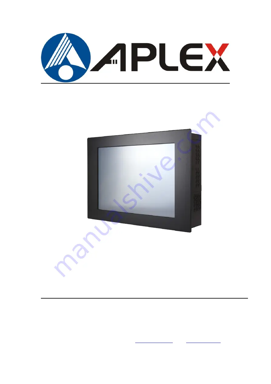
APC-3X19A
15”, 17”, and 19” 4
th
Gen. Intel Core i7/i5/i3 Panel PC
User Manual
Release Date Revision
Oct. 2015 V1.0
®2015 Aplex Technology, Inc. All Rights Reserved. Published in Taiwan
Aplex Technology, Inc.
15F-1, No.186, Jian Yi Road, Zhonghe District, New Taipei City 235, Taiwan
Tel: 886-2-82262881 Fax: 886-2-82262883 E-mail:
URL:
Summary of Contents for APC-3X19A
Page 9: ...APC 3X19A User Manual 8 1 3 Dimentions Figure 1 1 Dimensions of APC 3519A ...
Page 10: ...APC 3X19A User Manual 9 Figure 1 2 Dimensions of APC 3719A ...
Page 11: ...APC 3X19A User Manual 10 Figure 1 3 Dimensions of APC 3919A ...
Page 19: ...APC 3X19A User Manual 18 2 2 Motherboard Layout Figure 1 11 Motherboard IMB 181 L Layout ...
Page 56: ...APC 3X19A User Manual 55 Step 3 Click Yes Step 4 Click Next to continue ...
Page 69: ...APC 3X19A User Manual 68 Step 3 Click Yes to continue Step 4 Click Next to continue ...
Page 71: ...APC 3X19A User Manual 70 Step 2 Click Next to continue Step 2 Click Next to continue ...
Page 98: ...APC 3X19A User Manual 97 Hardware Saturn Hardware Configuration ...
Page 99: ...APC 3X19A User Manual 98 About To display information about eGalaxTouch and its version ...