AHM-6XX6A User Manual
0
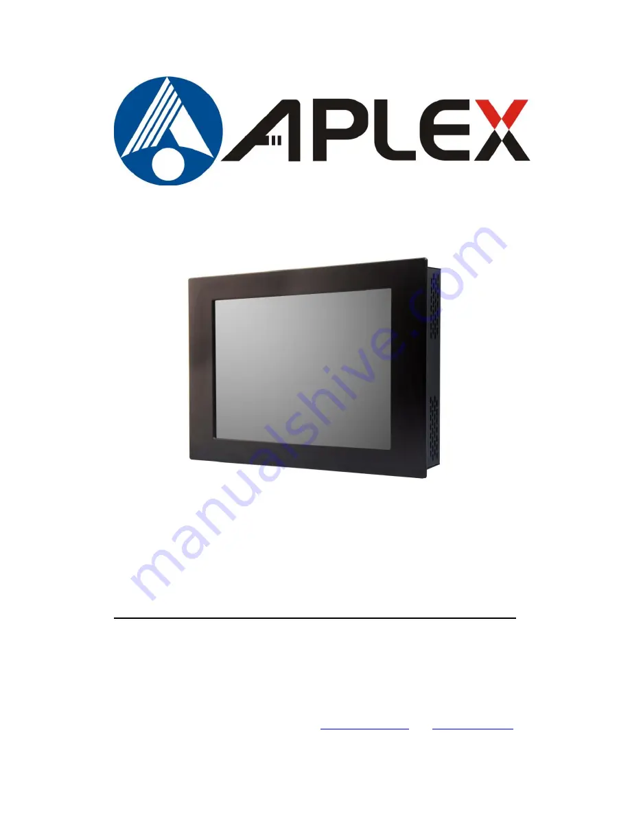
AHM-6XX6A
8”, 12.1”, 15”, 17”, 19” Intel Atom D525 Fanless HMI Series
User Manual
Release Date Revision
Jul. 2015 V1.4
®2015 Aplex Technology, Inc. All Rights Reserved. Published in Taiwan
Aplex Technology, Inc.
15F-1, No.186, Jian Yi Road, Zhonghe District, New Taipei City 235, Taiwan
Tel: 886-2-82262881 Fax: 886-2-82262883 E-mail:
URL:
www.aplextec.com
Summary of Contents for AHM-6XX6A
Page 9: ...AHM 6XX6A User Manual 8 1 2 Dimensions Figure 1 1 Dimensions of the AHM 6086A ...
Page 10: ...AHM 6XX6A User Manual 9 Figure 1 2 Dimensions of the AHM 6126A ...
Page 11: ...AHM 6XX6A User Manual 10 Figure 1 3 Dimensions of the AHM 6156A ...
Page 12: ...AHM 6XX6A User Manual 11 Figure 1 4 Dimensions of the AHM 6176A ...
Page 13: ...AHM 6XX6A User Manual 12 Figure 1 5 Dimensions of the AHM 6196A ...
Page 63: ...AHM 6XX6A User Manual 62 ...
Page 66: ...AHM 6XX6A User Manual 65 ...
Page 67: ...AHM 6XX6A User Manual 66 ...
Page 70: ...AHM 6XX6A User Manual 69 ...
Page 73: ...AHM 6XX6A User Manual 72 Click FINISH A Driver Installation Complete ...
Page 77: ...AHM 6XX6A User Manual 76 5 Installing ...
Page 78: ...AHM 6XX6A User Manual 77 6 The Install Shield Wizard Completed appears Click Finish ...