AnaPico APPH6000, User Manual
The AnaPico APPH6000, a premium signal generator, delivers exceptional performance that meets your testing requirements. Easily access its comprehensive User Manual, available for free download from our website. This guide equips you with in-depth knowledge to maximize the potential of your AnaPico APPH6000, ensuring seamless operation.
Share
Download


Reviews:
No comments
Related manuals for APPH6000
FPSTFP4253
Brand: Oster Pages: 16

UP&DOWN
Brand: R.G.V. Pages: 16

OVATIO AT7
Brand: Moulinex Pages: 2

943881
Brand: Springlane Pages: 80

S500LBW
Brand: Gorenje Pages: 35

FP408
Brand: Magiccos Pages: 2
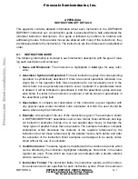
Freescale Semiconductor DSP56000
Brand: Motorola Pages: 126

HR7776/91
Brand: Philips Pages: 3

HR7605
Brand: Philips Pages: 44

SMZE 500 C2
Brand: Silvercrest Pages: 52

SMZ CD 400 A 1
Brand: Silvercrest Pages: 49

SMZE 500 A1
Brand: Silvercrest Pages: 63

SMZCD 400 A1
Brand: Silvercrest Pages: 63

MONSIEUR CUISINE CONNECT
Brand: Silvercrest Pages: 40

281064-B
Brand: Silvercrest Pages: 19

322511 1901
Brand: Silvercrest Pages: 34

288402
Brand: Silvercrest Pages: 75

MONSIEUR CUISINE EDITION PLUS
Brand: Silvercrest Pages: 119


