

Installation Guide
MAX-HT Rack Rail Kit
Overview
Each MAX-HT server comes with a Rack-Mounting Kit. Each Rack-Mounting Kit
supports one server and includes all hardware required to mount HT servers in a
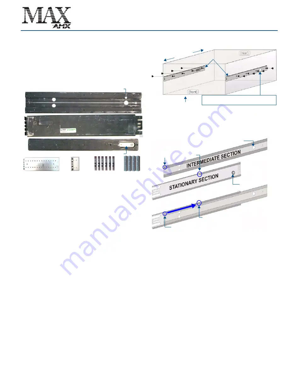
standard 19-inch (48-cm) equipment rack. The parts included in the Kit include:
•
2 Slide Rail Assemblies (each consists of a
Stationary section
, an I
ntermediate
section
and a
Chassis section
; pre-assembled for shipping)
•
2 Extension Brackets
•
2 End Brackets
•
6 Locking Plates (4-hole) -
not required
•
4 Adapter Bars (9-hole)
•
10 flat-head screws, 10 round-head screws
Note: You may not need all the parts included in the kit for every installation.
Before you begin, disassemble the Slide Rail Assemblies: the Stationary, Intermediate
and Chassis sections must be separated before they can be attached to the server
and rack.
CAUTION: Safety Instructions
Use the following safety guidelines to help ensure your own personal safety and to help protect your
system and working environment from potential damage.
CAUTION
: Installing systems in a rack without the front and side stabilizers installed could cause the rack
to tip over, potentially resulting in bodily injury under certain circumstances. Therefore, always install the
stabilizers before installing components in the rack.
After installing system/components in a rack, never pull more than one component out of the rack on its
slide assemblies at one time. The weight of more than one extended component could cause the rack to
tip over and may result in serious injury.
CAUTION
: Do not move racks by yourself. Due to the height and weight of the rack, a minimum of two
people should accomplish this task.
•
Before working on the rack, make sure that the stabilizers are secured to the rack, extended to the
floor, and that the full weight of the rack rests on the floor. Install front and side stabilizers on a sin-
gle rack or front stabilizers for joined multiple racks before working on the rack.
•
Always load the rack from the bottom up, and load the heaviest item in the rack first.
•
Make sure that the rack is level and stable before extending a component from the rack.
•
Use caution when pressing the component rail release latches and sliding a component into or out
of a rack; the slide rails can pinch your fingers.
•
After a component is inserted into the rack, carefully extend the rail into a locking position, and
then slide the component into the rack.
•
Do not overload the AC supply branch circuit that provides power to the rack. The total rack load
should not exceed 80 percent of the branch circuit rating.
•
Ensure that proper airflow is provided to components in the rack.
•
Do not step on or stand on any component when servicing other components in a rack.
Step 1: Install Chassis Sections Onto The Server Chassis
The Chassis Sections mount directly to the server chassis, using the middle row of
screws on the server chassis.
The server has plastic plugs in the holes that you will use to attach the Chassis
Sections, to keep the server chassis sealed in case the server is not rack-mounted.
To see how these parts will mount, visually align the Chassis Sections with the middle
row of plugs on each side of the server, so that the four screw holes on the Chassis
Section rail align with the middle row of plugs on the server.
Note
: Make sure to orient the Chassis Sections so that the locking tab button is facing
outwards, and located toward the rear of the server.
1.
Remove the four plastic plugs from each side of the MAX server.
2.
Install the chassis sections onto the MAX server chassis using 4 flat-head
PHILLIPS screws (included) per side, as shown in FIG. 2.
Step 2: Slide Intermediate Sections Into the Stationary Sections
1.
Slide the Intermediate Section into the Stationary Section, from the rear end of
the Stationary Section, as shown in FIG. 3.
2.
Press the Locking Tab on the Stationary Section to allow the Intermediate Sec-
tion to slide fully into place.
3.
Slide the Intermediate Section in, to the point that the Breaker tab on the Inter-
mediate Section rests against the Stopper on the top guide-rail on the Stationary
Section, and the locking tab snaps into place.
Step 3: Attach the Extension Brackets
With the Intermediate and Stationary Sections together, you can now attach the
Extension Brackets. The Extension Brackets attach to the rear end of the Stationary
Section, and allow the Rail Assembly to be anchored to the rear of the equipment rack.
Note that the Extension Brackets are designed to accommodate a range of depths.
Attach the brackets to the Rail Assemblies so that the rear mounting tabs reach the
rear of the equipment rack, while the front mounting tabs reach the front of the rack.
1.
Measure (or estimate) the depth required by your equipment rack, to get an idea
of how far forward or back the Extension Bracket should be mounted on the Rail
Assemblies.
Depending on the space required, you may choose to use the End Brackets
rather than the Extension Brackets.
2.
Loosely mount the Extension Brackets to the Rail Assemblies, using the
(included) round-head screws, as shown in FIG. 4.
•
Do not tighten the screws until the assembly is mounted into the rack.
•
Verify that the mounting tabs on the Rail Assemblies and the Extension brackets
are facing the same direction. The mounting tabs are used to secure the assem-
bly to the vertical mounting rails on the equipment rack.
FIG. 1
Included Rack Kit Parts
Locking Release Tab
Extension Brackets (2)
CHASSIS SECTION (2)
End Brackets (2)
Locking Plates (6)
Screws: 10 round head, 10 flat head, 10 locking nuts
Adapter Bars (4)
INTERMEDIATE SECTION (2)
STATIONARY SECTION (2)
Locking Tab Hole
FIG. 2
Attaching the Chassis Sections to the server chassis
FIG. 3
Sliding the Intermediate Section into the Stationary Section
The Locking Tab on each Chassis Section should
be oriented towards the rear of the server
Chassis Sections
(front)
(rear)
HT Server chassis
(rear)
Breaker tab
Stopper
Locking tab
Locking tab hole
Breaker Post (on Intermediate Section)
Stopper (on Stationary Section’s top guide-rail)
(front)


