Amplitec C15F-5B, User Manual
Looking for a User Manual for the Amplitec C15F-5B? Look no further! Download the comprehensive manual for free from manualshive.com. With clear instructions and detailed illustrations, this manual will guide you through every feature of your Amplitec C15F-5B, ensuring a seamless user experience. Get yours today!
Share
Download


Reviews:
No comments
Related manuals for C15F-5B
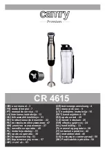
5902934830515
Brand: camry Pages: 64

LE BLENDER
Brand: MAGIMIX Pages: 65

BLSTMG-W00-074
Brand: Oster Pages: 9

Digital Blender
Brand: Oster Pages: 10

TBLI-1500
Brand: TECHWOOD Pages: 12

Q Mixer 6632
Brand: OBH Nordica Pages: 32

1599A
Brand: Altec Pages: 12

B-560-EXT-444-70
Brand: Binary Pages: 16

CopperLink 2168
Brand: Patton electronics Pages: 28

REC44M
Brand: Amped Wireless Pages: 86

29550
Brand: Cables to Go Pages: 6

230602
Brand: Hendi Pages: 100

HBH350 Series
Brand: Hamilton Beach Commercial Pages: 16

RG2301
Brand: Icron Pages: 2

Extender AAP
Brand: Extron electronics Pages: 36

21.4000.00.00
Brand: Bourgini Pages: 28

NY-GS10
Brand: Nyrius Pages: 4

CRD216SS
Brand: CLEAN ROOM DEVICES Pages: 22


