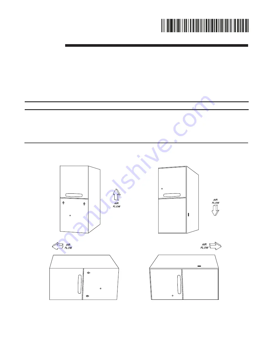
manualshive.com logo in svg
background image

UPFLOW

*UHM

UPFLOW/HORIZONTAL

*DHM

DOWNFLOW

DOWNFLOW/HORIZONTAL

*UHMB060ACV3VB

*UHMB080ACV3VB

*UHMC100ACV4VB

*UHMD120ACV5VB

Upflow/ Horizontal and Downflow/ Horizontal,

Gas-Fired, Direct Vent, Variable Speed Inducer, Modulating 

Condensing Communicating furnaces

ALL phases of this installation must comply with NATIONAL, STATE AND LOCAL CODES

IMPORTANT

 — This Document is customer property and is to remain with this unit.  

Please return to service information pack upon completion of work.

Installer’s Guide

*DHMB060BCV3VB

*DHMB080ACV3VB

*DHMC100ACV4VB

*DHMD120BCV5VB

* First letter may be “A” or “T"

1.  Safety signal words are used to designate a degree or level of seriousness associated with a particular hazard. 
2.  The signal words for safety markings are WARNING, and CAUTION.
3.   a. WARNING indicates a potentially hazardous situation which, if not avoided, could result in death or serious injury.
4.   b. CAUTION indicates a potentially hazardous situation which, if not avoided, may result in minor or moderate injury. It 

is also used to alert against unsafe practices and hazards involving only property damage.

A341624P14

NOTE:

This furnace can be configured for Communicating or 24 VAC modes. Using fully Communicating or 24 VAC 

modes, the furnace can support single or multi-stage heat pump, AC, or heating only applications. Combined with 

a communicating Comfort Control only, the furnace will support a single stage 24 VAC cooling outdoor unit only.

18-CD30D1-20-EN

Содержание ADHMB060BCV3VB

Страница 1: ...gnate a degree or level of seriousness associated with a particular hazard 2 The signal words for safety markings are WARNING and CAUTION 3 a WARNING indicates a potentially hazardous situation which if not avoided could result in death or serious injury 4 b CAUTION indicates a potentially hazardous situation which if not avoided may result in minor or moderate injury It is also used to alert agai...

Страница 2: ... use s s WARNING Failure to follow safety warnings exactly could result in a fire or explosion causing property damage personal injury or loss of life Do not store or use gasoline or other flammable vapors and liquids in the vicinity of this or any other appliance WHAT TO DO IF YOU SMELL GAS Do not try to light any appliance Do not touch any electrical switch do not use any phone in your building ...

Страница 3: ...for gas leaks with an open flame Use a commercially available soap solution made specifically for the detection of leaks to check all connections as specified in the Gas Piping section starting on page 34 6 Always install the furnace to operate within the furnace s intended temperature rise range with a duct system which has an external static pressure within the allowable range as specified on th...

Страница 4: ...H PLUG NOTES 1 DIAMETER OF VENT PIPE MAY BE LIMITED TO 2 1 2 OR 3 ON SOME MODELS AT DIFFERENT ALTITUDES REFER TO THE VENT LENGTH TABLE FOR PROPER APPLICATION MAY BE T OR A UHM ACV OUTLINE DRAWING ALL DIMENSIONS ARE IN INCHES MODEL SEE NOTE 1 DIM A DIM B DIM C DIM D DIM E DIM F UHMB060ACV3VB UHMB080ACV3VB 17 1 2 2 1 4 16 1 4 16 7 1 2 2 UHMC100ACV4VB 21 2 1 2 19 3 4 19 1 2 9 3 UHMD120ACV5VB 24 1 2 2...

Страница 5: ... 2 OVAL GAS CONNECTION NOTES 1 DIAMETER OF VENT PIPE MAY BE LIMITED TO 2 1 2 OR 3 ON SOME MODELS AT DIFFERENT ALTITUDES REFER TO THE VENT LENGTH TABLE FOR PROPER APPLICATION MAY BE T OR A DHM ACV DOWNFLOW HORIZONTAL OUTLINE DRAWING ALL DIMENSIONS ARE IN INCHES MODEL SEE NOTE 1 DIM A DIM B DIM C DIM D DHMB060BCV3VB DHMB080ACV3VB 17 1 2 2 1 4 16 1 4 16 DHMC100ACV4VB 21 2 1 2 19 3 4 19 1 2 DHMD120BCV...

Страница 6: ...f 24 inches front accessibility to the furnace must be provided Any access door or panel must permit removal of the largest component 4 Are there at least 3 inches of clearance between the furnace combustion air openings in the front panel and any closed panel or door provided 5 Are the ventilation and combustion air openings large enough and will they remain unobstructed If outside air is used ar...

Страница 7: ...ce platform large enough to allow for proper clearances on all sides and service access to the front of the furnace See Figure 5 Clearance Tables on the Outline drawings on pages 4 5 Line contact is only permissible between lines formed by intersections of the top and two sides of the furnace casing and building joists studs or framing The furnace may be placed horizontally in a crawl space on a p...

Страница 8: ...proximately 4 6 inches to allow clearance for the condensate drain to exit the cabinet in the horizontal position The horizontal furnace may also be suspended from the joists using all thread rods with a substantial metal support frame that supports the entire length of the furnace The rods need to be of sufficient length to allow for proper clearances from combustible materials The frame needs to...

Страница 9: ...gs one commencing within 12 inches of the top and one commencing within 12 inches of the bottom of the enclosure The openings shall communicate directly or by ducts with the outdoors or spaces crawl or attic that freely communicate with the outdoors Refer to Table 3 for minimum open areas requirements TABLE 3 MINIMUM FREE AREA IN SQUARE INCHES EACH OPENING FURNACE ONLY furnace Maximum BTUH INPUT R...

Страница 10: ...ystem the return connection must be run full size from the furnace to a location outside the utility room basement attic or crawl space Do NOT install return air through the back of the furnace cabinet Do NOT install return air through the side of the furnace cabinet on horizontal applications NOTE Minimum return air temperature is 55 F PREPARATION FOR UPFLOW BOTTOM AND SIDE RETURN AIR FILTER INST...

Страница 11: ...800 CFM Models will require return air openings and filters on 1 both sides or 2 one side and the bottom or 3 just the bottom The filter rack installation is not allowed for right side return on the following models UHMB060ACV3V UHMB080ACV3V UHMC100ACV4V The furnace and the bottom filter rack BAYRACK960 installation can be seen in Figure 11 The furnace filter in the bottom or side configuration ca...

Страница 12: ...igure 21 for alternate upflow filter clip bracket installation The following checklist should be used when installing a right or left side return filter on an upflow furnace a Remove the filter b Leave the bottom panel in place c Make side cutout by following the directions in the Return Air Duct Connections section on page 10 d Compress the filter rack and reinstall in the side position on the fu...

Страница 13: ...pending on the location of the return air filter A score line and the words CUT HERE are located on the end of the filter If your application requires Typical Horizontal Filter Installation Airflow BLOWER DECK Filter Rack Assembly Furnace Blower Deck Filter Rack Retaining Screw Pin Engagement Hole For Return Filter Rack Installation With Side Furnace Cabinet Side Table 4A CONVERSION KITS FOR HORIZ...

Страница 14: ...er compartment They are wrapped in foam and taped to the side of the downflow unit Remove the four screws securing the top panel Save screws Slide the top panel forward approximately 1 With support tabs facing up install the filter base by inserting one end tab into the duct flange at the rear of the furnace Slide the top panel back to its original position engaging the other end tab in the slot R...

Страница 15: ...lined below for each appliance connected to the venting system being placed into operation could result in carbon monoxide poisoning or death The following steps shall be followed for each appliance connected to the venting system being placed into operation while all other appliances connected to the venting system are not in operation 1 Seal any unused openings in the venting system 2 Inspect th...

Страница 16: ...zontal venting when the factory supplied off set 2X3 reducing coupling is used for 3 vent pipe installation make sure the marking Top is located on the top side of the pipe The straight side must be on bottom for proper condensate drainage This coupling is factory supplied with the following models UHMC100 UHMD120 all downflow models s s WARNING Carbon monoxide fire or smoke can cause serious bodi...

Страница 17: ...e 9 page 18 are designations for different types of 2 and 3 size pipe and fittings that meet these requirements The materials listed are various grades of PVC CPVC ABS PolyPro by DuraVent Z Dens by Novaflex Group Innoflue by Centrotherm and PolyFlue polypropylene venting systems ATTACHING VENT PIPING Important Products installed in Canada must use vent systems that are certified to the Standard fo...

Страница 18: ...er tight Flue condensate is somewhat acidic and leaks can cause equipment damage IMPORTANT Products installed in Canada must use vent systems that are certified to the Standard for Type BH Gas Venting Systems ULC S636 for Class II A venting systems up to 65 C Components of the vent system must not be interchanged with other vent systems or unlisted pipe or fittings Plastic components specified pri...

Страница 19: ...wed 200 150 Not Allowed Not Allowed Not Allowed Not Allowed 100 100 Not Allowed Not Allowed Not Allowed Not Allowed 50 38 NOTES First letter may be A or T 1 For PolyPro by Duravent Z DENS by Novaflex Group InnoFlue by Centrotherm and Polyflue manufactured modular venting systems that are in the approved vent pipe material table 9 fitting equivalent vent lengths may be different from what is shown ...

Страница 20: ...es through unheated spaces etc the pipe must be insulated with 1 2 inch 22 7 mm thick Armaflex type insulation or equal If the space is heated sufficiently to prevent freezing then the insulation would not be required If domestic water pipes are not protected from freezing then the space meets the condition of a heated space VENTING THROUGH THE ROOF When penetrating roof with a 2 PVC Vent Pipe a 2...

Страница 21: ...e and local codes The vent inlet terminals must be located at least 12 minimum above normally expected snow accumulation level See Figure 29 Avoid areas where staining or condensate drippage may be a problem Location of the vent wind terminal should be chosen to meet the requirements of Figure 30 and Tables 11 and 12 for either direct or non direct vent applications PITCH Venting through the wall ...

Страница 22: ...TORS Each carbon monoxide detector as required in accordance with the above provisions shall comply with NFPA 720 and be ANSI UL 2034 listed and IAS certified The manufacturer of the furnace does not test any carbon monoxide detectors and makes no representation regarding any brand of carbon monoxide detector 3 SIGNAGE A metal or plastic identification plate shall be permanently mounted to the ext...

Страница 23: ... fittings and fitting accessories are to be supplied locally For Canadian applications horizontal vent termination kits must meet ULC S636 HORIZONTAL VENT CLEARANCES See clearance tables 11 and 12 on page 24 V D E E V G INSIDE CORNER DETAIL B L V V FIXED CLOSED OPERABLE F B C V FIXED CLOSED V V V B B B A X J B H I V X K M V VENT TERMINAL X AIR SUPPLY INLET AREA WHERE TERMINAL IS NOT PERMITTED OPER...

Страница 24: ...tallation Instructions Table 12 Direct Vent Terminal Clearances Canadian Installations US Installations A Clearance above grade veranda porch deck or balcony 12 inches 30 cm 12 inches 30 cm B Clearance to window or door that may be opened 6 inches 15 cm for appliances 10 000 Btuh 3 kw 12 inches 30 cm for appliances 10 000 Btuh 3 kw and 100 000 Btuh 30 kw 36 inches 91 cm for appliances 100 000 Btuh...

Страница 25: ... THROUGH COMBUSTIBLE WALLS Pitch 1 4 Inch Per Foot CLEARANCE 0 ACCEPTABLE FOR PVC VENT PIPE 1 ACCEPTABLE FOR TYPE 29 4C STAINLESS STEEL VENT PIPE 12 MINIMUM ABOVE NORMALLY EXPECTED SNOW ACCUMULATION LEVEL 6 IN MIN TO JOINT COUPLING PLASTIC VENTING PVC WALL MOUNT FLANGE OPTIONAL APPROVED TERMINATION CEMENT MORTAR SEAL INSIDE OUTSIDE VENTING THROUGH NON COMBUSTIBLE WALLS Pitch 1 4 Inch Per Foot 12 M...

Страница 26: ...AINTAINED ABOVE HIGHEST ANTICIPATED SNOW LEVEL MAXIMUM NOT TO EXCEED 24 INCHES ABOVE ROOF For Canadian applications verti cal vent termination kits must meet ULC S636 REMOVE RIBS FROM CAP COMBUSTION AIR ROOF FLASHING BOOT FIELD SUPPLIED COMBUSTION AIR VENT ELBOW FIELD SUPPLIED MAINTAIN 12 IN 18 IN FOR CANADA MINIMUM CLEARANCE ABOVE HIGHEST ANTICIPATED SNOW LEVEL MAXIMUM OF 24 IN ABOVE ROOF SUPPORT...

Страница 27: ...TICAL VENTING 6 IN MIN SEE CAUTION STAINLESS STEEL VENT CAP OPTIONAL SUPPORT THE SINGLE WALL FLUE PIPE AND CENTER IT IN THE CHIMNEY OPENING WITH ANGLES AS SHOWN OR ANOTHER EQUIVALENT MANNER NOTE HORIZONTAL VENTING TO VERTICAL VENTING 6 IN MIN STAINLESS STEEL VENT CAP OPTIONAL SEE CAUTION FLUE PIPE COUPLING AS REQUIRED FLUE PIPE COUPLING TO SUPPORT PIPE FROM ANGLES OR OTHER SUITABLE SUPPORT METHOD ...

Страница 28: ...lectrical source is utilized The integrated furnace control is polarity sensitive The hot leg of the 120V power supply must be connected to the Black power lead as indicated on the wiring diagram Provision for hooking up an Electronic Air Cleaner and or Humidifier is provided on the Integrated Control Refer to the Service Facts literature and unit wiring diagram attached to the furnace NOTE The B ...

Страница 29: ... 20 EN 29 Installer s Guide 41B Communicating Indoor Unit with Communicating Comfort Control and 24VAC Single Stage Cooling 41C 24 VAC Mode Indoor Unit with 24 VAC Comfort Control and 24VAC Single Stage Cooling ...

Страница 30: ...ller s Guide 41D 24 VAC Mode Indoor Unit with 24 VAC Comfort Control and 24VAC 2 Stage or 2 Step Cooling 41E 24 VAC Mode Indoor Unit with 24 VAC Comfort Control and 24VAC Single Stage Heat Pump Field Wiring Diagrams continued ...

Страница 31: ...tween R and BK on the circuit board must be cut if an op tional humidistat is installed HUMIDISTAT HOOKUP 24 V ONLY If an optional humidistat for humidity control in cooling is used the factory installed BK Jumper must be cut The BK Jumper must also be cut if a multi zone controller is connected to CONT402 is installed and using the BK enabled feature See the 24VAC field wiring diagrams for more i...

Страница 32: ...f the second ary heat exchanger drain connection to prevent water from damaging furnace controls if the primary drain outlet plugs up Where the furnace is installed above a finished ceiling the primary drain vent stack must be installed such that overflow from the vent stack opening will flow into an auxiliary drain pan in order to prevent water dam age to the finished ceiling below See Figure 42 ...

Страница 33: ...d reposition into the other drain tap of the inducer which is located 90 clockwise around the inducer Move the cap from that drain tap to the unused drain tap On upflow units plug the hole in the blower deck where the tube went through with factory supplied cap Use extension hose here UPFLOW HORIZONTAL 21 24 UNITS LEFT SIDE ONLY UPFLOW HORIZONTAL 17 UNITS LEFT SIDE ONLY Use Inducer Drain hose with...

Страница 34: ... prevent damage to the Gas Valve and Manifold Assembly The upflow horizontal furnace is shipped standard for left side installation of Gas Piping A cutout is provided on the right side for an alternate Gas Piping arrangement The installation of piping shall be in accordance with piping codes and the regulations of the local gas company Pipe joint compound must be resistant to the chemical reaction...

Страница 35: ...IGHT HAND GAS PIPING AUTOMATIC GAS VALVE WITH MANUAL SHUT OFF AUTOMATIC GAS VALVE WITH MANUAL SHUT OFF DRIP LEG DRIP LEG DRIP LEG DRIP LEG IMPORTANT A sediment trap must be installed in the gas line before the furnace gas valve The sediment trap must be located as close to the furnace cabinet as practical IMPORTANT A sediment trap must be installed in the gas line before the furnace gas valve The ...

Страница 36: ... revolution for a meter on which one revolution indicates 2 cubic feet per hour of gas flow For other meters use the following conversions a For 1 Cu Ft Dial Gas Flow CFH Chart Flow Reading 2 b For 1 2 Cu Ft Dial Gas Flow CFH Chart Flow Reading 4 c For 5 Cu Ft Dial Gas Flow CFH 10X Chart Flow Reading 4 3 Multiply the final figure by the heating value of the gas obtained from the utility company an...

Страница 37: ...0 33 218 54 133 90 80 13 555 34 212 55 131 92 78 14 514 35 206 56 129 94 76 15 480 36 200 57 126 96 75 16 450 37 195 58 124 98 73 17 424 38 189 59 122 100 72 18 400 39 185 60 120 104 69 19 379 40 180 62 116 108 67 20 360 41 176 64 112 112 64 21 343 42 172 66 109 116 62 22 327 43 167 68 106 120 60 23 313 44 164 70 103 124 58 24 300 45 160 72 100 128 56 25 288 46 157 74 97 132 54 26 277 47 153 76 95...

Страница 38: ...essure Switch PS 3 Pressure Switch PS 2 Negative Control Pressure Post Positive Control Pressure Post Modulating Gas Valve Orifice in H fitting must be pointing away from PS1 VACUUM HOSE ROUTING To Pressure Switch PS 1 Important Brass orifices located in these two legs H Fitting must be installed in this orientation E R ...

Страница 39: ...be cleaned annually using brushes and vacuum cleaner gas that might have escaped to dissipate LP Gas being heavier than air may require forced ventilation Turn the toggle switch on the Gas Valve in the unit to the ON position All soap solution should be cleaned off gas piping after gas leak testing is complete LIGHTING INSTRUCTIONS s s WARNING FIRE OR EXPLOSION HAZARD Do NOT attempt to manually li...

Страница 40: ... ENTER Push left right to scroll through menu options Push up down to scroll through setup menu Push ENTER to make selection Viewing Window User Interface pictured above adjusts Variable Speed Airflow options and is used for custom setup of furnace operations See menu options in User Interface on pages 45 46 2 Lower door panel and remove from service access area 3 Use one hand depress the door swi...

Страница 41: ...0 1500 1600 A TDHMD120 1850 1850 2040 1660 1760 Information Menu Information Options MODEL NUMBER MODEL A TUHM SERIAL NUMBER SERIAL SW REV NUMBER SW REV NUMBER SYSTEM STATUS SYSTEM STATUS OFF REQUESTED CFM REQUESTED CFM 0 CFM LAST 4 FAULTS LAST 4 FAULTS NO ALERTS INDOOR ALERTS INDOOR ALERTS NO ALERTS UNIT TEST UNIT TEST UNIT TEST UNIT TEST SIMPLE GAS VAL SETUP TEMP SENSOR TEMP SENSOR SNSR1 SNSR1 S...

Страница 42: ...HMB080 1400 1400 1610 1120 1260 A TUHMC100 1620 1620 1790 1460 1540 CONT FAN CFM A TUHMD120 1890 1890 2000 1700 1790 CONT FAN CFM 50 50 25 A TDHMB060 1040 1040 1160 900 950 A TDHMB080 1400 1400 1610 1300 1350 FAN PRERUN DLY FAN PRERUN DLY A TDHMC100 1650 1650 1700 1500 1600 NONE NONE 1m 50 A TDHMD120 1850 1850 2040 1660 1760 FAN SHRTRUN DLY FAN SHRTRUN DLY NONE NONE 4m 80 7 5m 80 FAN OFF DLY FAN O...

Страница 43: ...tor drive board to ramp down to that corresponding demand speed The reduction of the vent motor speed in steps allows the gas flow through the gas valve to also be reduced in steps decreasing the chance of burner flame out The minimum capacity change is 1 15 The minimum capacity of all furnaces is 40 with the exception of the UHMC120 The minimum capacity for this furnace is 45 16 The communicating...

Страница 44: ...door blower motor speed Thermostat call for W2 after W1 12 R and W2 thermostat contacts close signaling a call for W2 heat The IFC then signals the variable speed inducer drive to ramp up the vent motor allowing flow through the gas valve to also be increased in 3 steps 13 If the call for W2 remains this 3 increase will be repeated every 1 minute until the capacity requested is 100 The IFC will al...

Страница 45: ...al the vent motor to ramp up The increase of the vent motor speed allows the gas flow through the gas valve to also be increased in 3 steps This 3 increase will be repeated every 1 minute until the capacity requested is 100 Pressure switch 3 closes at approximately 95 of capacity 26 The IFC will also increase the indoor blower motor speed in appropriate steps Indoor Blower motor operation thermost...

Страница 46: ...on e When asked Are You Sure select Yes and push the Enter button f The furnace will now begin the ignition sequence g If pressure switch 1 2 learning routines have not been performed after successful ignition the inducer will go through this operation see Inducer Learning Routine section h Allow 5 minutes to pass before attempting to adjust UNIT TEST MODE A SIMPLE Note Stage 1 40 low heat Stage 2...

Страница 47: ...able 10 0 0 5 100 2 1 0 5 Not Adjustable 10 0 0 5 Downflow 120 2 1 0 5 Not Adjustable 10 0 0 5 Upflow 120 2 9 0 5 Not Adjustable 10 0 0 5 For upflow 120KBTU hr model 1st stage is 45 Manifold pressures apply for Propane applications ONLY furnace Input rate KBTU hr FINAL NG MANIFOLD PRESSURE SETTINGS inches w c 40 65 100 60 0 7 0 2 0 0 Not Adjustable 3 5 0 2 80 0 7 0 2 0 0 Not Adjustable 3 5 0 2 100...

Страница 48: ...and that the heat rise is stable j Read the 100 manifold pressure k If needed remove the high heat manifold adjustment cover and adjust to obtain the correct manifold pres sure See Figure 59 100 HIGH HEAT ADJUSTMENT COUNTERCLOCKWISE TO DECREASE MANIFOLD PRESSURE OR CLOCKWISE TO IN CREASE MANIFOLD PRESSURE l Use Manifold Pressure Settings Table 22 for the correct manifold pressure setting in Inches...

Страница 49: ...TAGE and OFF OFF will now be displayed First or Second heat stage must be selected Use the or arrows to select the stage of heat wanted and then push the Enter button and then the button DUTY CYCLE and 10 10 will now be displayed A duty cycle must now be selected from 10 to 50 A 10 duty cycle will run the furnace for 2 minutes and then off for 18 minutes A 50 duty cycle will run the furnace for 10...

Страница 50: ...YES and then press the ENTER button Are you Sure and NO NO will now be displayed With a NO NO question being asked use the or arrows to select the YES and then press the ENTER button Turn 115VAC power off When the Green LED on the variable speed inducer drive goes out turn 115 VAC power back on When the furnace is operating in the contingency mode stand alone operating cycle the user interface wil...

Страница 51: ...ine for 100 high heat until it receives a call for 100 high heat PS 3 INDUCER LEARNING ROUTINE When the furnace IFC receives a digital signal for 100 high heat from the comfort control it will begin the PS 3 inducer learning routine The furnace will start the heating cycle in 65 medium heat if not already on and then begins the PS 3 inducer learning routine The furnace IFC will send a digital sign...

Страница 52: ...tart up by the installer To check for proper operation of the Limit Switches set the Comfort Control to a temperature higher than the in dicated room temperature to start the furnace Restrict the airflow by blocking the return air disconnecting the Indoor Blower may trip the Inducer Limit When the fur nace reaches the maximum outlet temperature as shown on the rating plate the burners must shut of...

Страница 53: ...ating Cycle or flame is not present at the sensor the Integrated furnace Con trol IFC will close the Gas Valve The Integrated furnace Control will then recycle the Ignition Sequence If Ignition is not achieved it will shut off the Gas Valve and lock out the system 3 POWER FAILURE If there is a power failure during a Heating Cycle the system will restart the Ignition Sequence automatically when pow...

Страница 54: ...re displayed on the User Interface menu using a descriptive text message and on the comfort control display using an alert code number A com plete list of the alert codes is included with the comfort control Table 23 LED DESCRIPTION FUNCTION GREEN STATUS LED FAST FLASH CALL FOR HEAT SLOW FLASH NO CALL FOR HEAT RED ALERT LED NO OF FLASHES SEE DIAGNOSTIC CODES GREEN BM BITMASTER ON SOLID WHEN UNIT P...

Страница 55: ...Communication Message has been detected while configured for 24V Mode Solid ON Device count CNTRL FAULT ERR 18 18 Control Failure Internal control failure None Device count TWIN ERROR N A 19 Twinning Fault Twinning Not Allowed with Variable Speed PM DATA ERR Data Section is Corrupt but PM is useable CAP MISMATCH Compressor size does not match capacity in PM ID MTR ERR Blower HP OEM does not match ...

Страница 56: ...e manufacturer has a policy of continuous data improvement and it reserves the right to change design and specifications without notice We are committed to using environmentally conscious print practices 2020 18 CD30D1 20 EN 16 Jun 2020 Supersedes 18 CD30D1 19 EN May 2019 This product may be covered by one or more of the following patents and their foreign equivalents 5621888 5901156 6208263 63533...

Отзывы: