American Panel Blast Chiller AP40BC250-12, Installation And Maintenance Manual
The American Panel Blast Chiller AP40BC250-12 is a top-of-the-line commercial appliance that rapidly cools food to safe temperatures. Ensure proper installation and maintenance by downloading the free Installation and Maintenance Manual from manualshive.com. Follow the manual for optimal performance and longevity of this high-quality blast chiller.
Share
Download


Reviews:
No comments
Related manuals for Blast Chiller AP40BC250-12
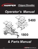
5400
Brand: Harper Pages: 38

YCIV 0590-1500 50Hz
Brand: York Pages: 12

FCS 22
Brand: AERMEC Pages: 15

31000231
Brand: Hoshizaki Pages: 19

EWWD370H-XS
Brand: Daikin Pages: 192

OEM-290-263
Brand: Troy-Bilt Pages: 8

Garden way 12215
Brand: Troy-Bilt Pages: 20

664D-Pony
Brand: Troy-Bilt Pages: 40

16LJ-F Series
Brand: Carrier Pages: 11

16JT080-150
Brand: Carrier Pages: 12

16JA
Brand: Carrier Pages: 12

FT5
Brand: Jonsered Pages: 28

Freezy 5
Brand: Nemox Pages: 33

321000001
Brand: Toro Pages: 80

AK CB20
Brand: MP Systems Pages: 81

FRZ 5800
Brand: Texas Equipment Pages: 28

TBC304
Brand: Troy-Bilt Pages: 40

Series 200 World Rear Wheel Tiller
Brand: Troy-Bilt Pages: 68


