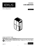
DH-100V
HIGH EFFICIENCY DEHUMIDIFIER
INSTALLATION
OPERATION
MAINTENANCE
972 DH
09-12
A L D E S D H - 1 0 0 V
Installation, Operation & Service Instructions
Table of Contents
1.
Specifications
....................................................... 1
2.
Installation
............................................................ 1
2.1
Location ............................................................ 1
2.1A In humid area, no ducting. .......................... 1
2.1B
In humid area, duct inlet and/or outlet
. .......... 1
2.1C In remote area, duct inlet & outlet............... 2
2.1D In remote area, duct outlet only. ................. 2
2.1E In remote area, duct inlet only. ................... 2
2.2 Electrical Requirements .................................... 2
2.3 Condensate Removal........................................ 2
2.4 Ducting .............................................................. 2
2.4A
Optional Ducting ........................................ 2
2.4B Ducting for Dehumidification ....................... 2
2.4C
Ducting
for Fresh Air................................... 3
3.
Operation
.............................................................. 3
3.1 Humidity Control Adjustment............................. 3
3.2 Fan Switch......................................................... 3
4.
Maintenance
......................................................... 3
4.1 Air Filter ............................................................. 3
4.2 Blower Oiling ..................................................... 3
5.
Service
.................................................................. 4
5.1 Warranty ............................................................ 4
5.2 Technical description ........................................ 4
5.3 Troubleshooting................................................. 4
5.4 Refrigerant Charging ......................................... 5
5.5 Blower Replacement ......................................... 5
5.6 Compressor/Capacitor Replacement................ 5
5.6A Checking Compressor Motor Circuits ......... 5
5.6B Replacing a Burned Out Compressor......... 5
5.6C
Replacing a Compressor- Nonburn Out .........
6
5.7 Humidity Control................................................ 6
5.8 Defrost Thermostat............................................ 6
5.9 Condensate Pump............................................. 6
6.
Wiring Diagrams
.................................................. 7
7.
Service Parts List
................................................. 8
8.
Warranty
................................................................ 9
9.
Service Notes
..................................................... 10
Serial No.________________________________
Purchase Date____________________________
Dealer's Name____________________________
Read the installation, operation and maintenance
instructions carefully
before
installing and using this unit.
Proper adherence to these instructions is essential to
obtain maximum benefit from your DH-100V
dehumidifier.
1 Specifications
Model: DH-100V Dehumidifier
Electrical: 110-120 VAC, 6.8 Amps, grounded
Capacity: 100 pints/day @ 80
°
F, 60% RH
Operating Temp. Range: 53
°
F min, 105
°
F max
Air Flow: 255 CFM without external ducting
170 CFM @ 0.15 in.wg. external static
Refrigerant Charge: 1 lbs., 14oz. R-22
Optional Duct connections: 8" round inlet & outlet
Size (w/o duct collars):
20" long x 17" wide x 36" high
Weight: 103 lbs.
2 Installation
2.1 Location
The DH-100V can be installed in a variety of locations to
meet the owner's needs as listed below. In all cases,
keep the following cautions in mind:
•
It is designed to be installed
INDOORS ONLY
.
•
If used near a pool or spa, be certain there is
NO
chance the unit could roll into the water or be
splashed and that it is plugged into a
GROUND
FAULT INTERRUPTER.
•
DO
NOT
use the DH-100V as a bench or table.
•
Avoid discharging the air directly at people,
especially in pool areas.
2.1A In humid area, no ducting
.
The simplest installation is to place the DH-100V in the
humid area with no ducting. The air inlet on top & outlet
on the side must be at least 1' from walls and other
obstructions to air flow.
2.1B In humid area, duct inlet and/or outlet
.
If the humid area is very large or has high ceilings,
dehumidification can be improved by adding an inlet
and/or outlet duct to circulate and destratify stagnant
areas. For a large area, add inlet or outlet ducting to
create flow across the area's greatest length.
For areas with ceilings higher than 12', use an inlet duct
to draw warm, moist air from near the ceiling. See
section 2.4 for attaching duct collars & ducting.
1


