background image

TM 9-2320-283-20-3

TECHNICAL MANUAL

ORGANIZATIONAL

MAINTENANCE

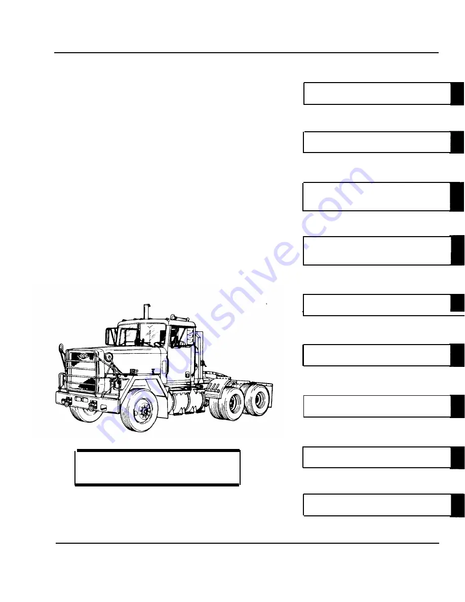
TRUCK TRACTOR, LINE HAUL,

50,000 GVWR, 6 x 4, M915A1

(NSN 2320-01-125-2640)

This copy is a reprint which includes current
pages from Change 1.

WHEELS

PAGE 3-1203

STEERING SYSTEM

PAGE 3-1245

FRAME AND TOWING

ATTACHMENTS

PAGE 3-1329

SPRINGS, SHOCK ABSORBERS,

AND TORQUE RODS

PAGE 3-1470

CAB AND BODY

PAGE 3-1492

ACCESSORY ITEMS

PAGE 3-1672

GAGES (NON-ELECTRICAL)

PAGE 3-1786

STE/ICE COMPONENTS

PAGE 3-1832

HEADQUARTERS,

DEPARTMENT 

OF 

THE ARMY

APPENDICES

PAGE A-1

DECEMBER 1983

Summary of Contents for M915A1

Page 1: ...ncludes current pages from Change 1 WHEELS PAGE 3 1203 STEERING SYSTEM PAGE 3 1245 FRAME AND TOWING ATTACHMENTS PAGE 3 1329 SPRINGS SHOCK ABSORBERS AND TORQUE RODS PAGE 3 1470 CAB AND BODY PAGE 3 1492...

Page 2: ...ng Company Gunite Division of Kelsey Hayes Co Holland Hitch Company Hupp Moble Products Division Leece Neville Sheller Globe Division McCord Heat Transfer Division of Ex Cell O Corporation Nelson Muff...

Page 3: ...e personnel heater or engine of vehicle in a closed place unless the place has a lot of moving air 2 DO NOT idle engine for long periods without ventilator blower operating 3 DO NOT drive any vehicle...

Page 4: ...terclockwise until you can remove it Failure to follow this procedure can result in serious burns WARNING Do not smoke have open flames or make sparks around the batteries especially if the caps are o...

Page 5: ...pipes and muffler can become very hot Be careful not to touch these compo nents with your bare hands Do not allow your body to come in contact with the hot pipes or muffler Exhaust system components...

Page 6: ...mission oil is hot Use care when draining transmission oil to pre vent personal injury WARNING Never work on air system components without first draining air pressure Failure to follow this precaution...

Page 7: ...distribution is unlimited TM 9 2320 283 20 3 8 December 1983 is changed as follows 1 Remove old pages and insert new pages as indicated below Remove Pages Insert Pages B 1 through B 4 B 1 through B 4...

Page 8: ...KER General United States Army Chief of Staff Official SANDRA R RILEY Administrative Assistant to the Secretary of the Army 0517807 DISTRIBUTION To be distributed in accordance with the initial distri...

Page 9: ...rtical bar adja cent to the TA number Remove Pages Insert Pages 3 1297 through 3 1304 E 7 and E 8 Index 15 and Index 16 3 1297 through 3 1304 11 blank 3 1304 12 E 7 and E 8 Index 15 and Index 16 3 Fil...

Page 10: ......

Page 11: ...THE FOLLOWING Page No Change No Cover Back Blank 0 A B Blank 2 i thru vi 0 3 1203 thru 1296 0 3 1297 thru 3 1304 1 3 1305 thru A 3 A 4 blank 0 B1 through B 4 2 B5 through B 29 2 C 1 through E 6 0 E 7...

Page 12: ...in the back of this manual directly to Commander U S Army Tank Automotive Command ATTN DRSTA MB Warren MI 48090 A reply will be furnished to you VOLUME 3 OF 3 Page Section XII WHEELS 3 201 General 3...

Page 13: ...3 230 Clevis Pin Replacement 3 231 Transmission Oil Filter Mounting Bracket 3 1372 Replacement 3 1376 3 232 Forward Rear Axle Stop Replacement 3 1380 3 233 Blackout Taillamp Mounting Bracket Replacem...

Page 14: ...3 1566 3 269 Hood Replacement 3 1576 3 270 Hood Panel and Component Replacement 3 1584 3 271 Front Fender Replacement 3 1600 3 272 Quarter Fender Replacement 3 1612 3 273 Splash Shield Replacement 3 1...

Page 15: ...1776 Data and Instruction Plates Replacement Winterization Kit Refer to TB 9 2320 283 14 3 1782 3 1786 Task Summary 3 1786 Tachograph Replacement 3 1788 Speedometer Shaft Replacement Speedometer Drive...

Page 16: ...C 1 Section I INTRODUCTION C 1 C 1 Scope C 1 C 2 Explanation of Columns C 1 Section II EXPENDABLE SUPPLIES AND MATERIALS LIST C 2 APPENDIX D SCHEMATIC DIAGRAMS D 1 Section I INTRODUCTION D 1 D 1 Scope...

Page 17: ......

Page 18: ...for this information TEST EQUIPMENT None SPECIAL TOOLS Handle 80201 450237 Adapter 80201 427 Plug bearing 80201 706 Wrench hexagon locknut 2 1 4 inch 45225 1920 MATERIALS PARTS P N Solvent drycleanin...

Page 19: ...ersonal Paragraph 2 11 injury or part damage could re sult from working on an inflated tire LIST OF TASKS TASK TASK TASK TROUBLESHOOTING NO REF REF NO PARA 1 Front Wheel Alinement 3 203 a Checking Ali...

Page 20: ...UBLESHOOTING NO REF REF N0 PARA 5 Rear Hub Bearings and Seals Replacement a Removal b Cleaning c Inspection d Installation 6 Tire Replacement 3 208 a Removal 3 208a b Cleaning and Inspection 3 208b c...

Page 21: ...RIPTION All TM 9 2320 283 10 Front tires properly inflated TEST EQUIPMENT None SPECIAL TOOLS None MATERIALS PARTS P N None PERSONNEL REQUIRED SPECIAL ENVIRONMENTAL CONDITIONS One MOS 63S Vehicle on le...

Page 22: ...TM 9 2320 283 20 3 WHEELS 3 203 FRONT WHEEL ALINEMENT Continued LEGEND 1 TOE IN GAGE 4 NUT 2 2 GAGE POINTER 5 TIE ROD TUBE ASSEMBLY 3 SCREW 2 TA 237566 3 1207...

Page 23: ...3 Gage 1 a Remove b From behind front wheels Gage 1 should be on install between tires so same spot of both tires both chains just touch ground 4 Pointer 2 Check reading Reading should be 1 32 1 32 fo...

Page 24: ...TM 9 2320 283 20 3 WHEELS 3 203 FRONT WHEEL ALINEMENT Continued LEGEND 1 TOE IN GAGE 2 GAGE POINTER 3 SCREW 2 4 NUT 2 5 TIE ROD TUBE ASSEMBLY TA 237567 3 1209...

Page 25: ...rycleaning SD 2 Item 29 Appendix C Rag wiping Item 22 Appendix C Solution soap Item 28 Appendix C PERSONNEL REQUIRED Two MOS 63S REFERENCES TM TM 9 2320 283 10 TROUBLESHOOTING REFERENCES Paragraph 2 1...

Page 26: ...TM 9 2320 283 20 3 WHEELS 3 204 FRONT DRUM REPLACEMENT Continued LEGEND 1 HUB AND CUP ASSEMBLY 2 FRONT BRAKE DRUM TA 237568 3 1211...

Page 27: ...cessary B CLEANING AND INSPECTION 2 Drum 2 a Clean with solvent and rag then with soap solution and water Refer to paragraph 3 4 b Inspect for cracks If damaged refer to scores gouges heat DS GS maint...

Page 28: ...TM 9 2320 283 20 3 WHEELS 3 204 FRONT DRUM REPLACEMENT Continued LEGEND 1 HUB AND CUP ASSEMBLY 2 FRONT BRAKE DRUM TA 237569 3 1213...

Page 29: ...ug bearing 80201 706 Wrench hexagon locknut 2 1 4 inch 45225 1920 MATERIALS PARTS P N Oil lubricating Gear GO Refer to LO 9 2320 283 12 Sealant flange Item 23 Appendix C Pin cotter 52304 H1005727 Seal...

Page 30: ...RONT AXLE BEARING SEAL ASSEMBLY 3 INNER BEARING CONE 4 INNER CUP 5 HANDLE 6 ADAPTER 7 SPACER 8 BEARING PLUG 9 LOCKWASHER 10 NUT 11 SCREW 6 12 LOCKWASHER 6 13 VENT PLUG OPTIONAL 14 PIPE PLUG 15 HUBCAP...

Page 31: ...rain 3 Hubcap 15 and gasket 16 Remove from item 22 Discard item 16 NOTE Plug 13 is an optional item 4 Plug 13 Remove from item 15 5 Pin 18 Remove from item 17 Discard item 18 6 Nut 17 washer 19 cone 2...

Page 32: ...RONT AXLE BEARING SEAL ASSEMBLY 3 INNER BEARING CONE 4 INNER CUP 5 HANDLE 6 ADAPTER 7 SPACER 8 BEARING PLUG 9 LOCKWASHER 10 NUT 11 SCREW 6 12 LOCKWASHER 6 13 VENT PLUG OPTIONAL 14 PIPE PLUG 15 HUBCAP...

Page 33: ...arts Clean and inspect Refer to paragraph 3 4 and 3 5 C INSTALLATION NOTE Put left hand threaded bolts in left hub and right hand threaded bolts in right hub 11 Ten new bolts 23 Install in item 22 Use...

Page 34: ...RONT AXLE BEARING SEAL ASSEMBLY 3 INNER BEARING CONE 4 INNER CUP 5 HANDLE 6 ADAPTER 7 SPACER 8 BEARING PLUG 9 LOCKWASHER 10 NUT 11 SCREW 6 12 LOCKWASHER 6 13 VENT PLUG OPTIONAL 14 PIPE PLUG 15 HUBCAP...

Page 35: ...17 16 Nut 17 a Torque to 50 lb ft b Back off between 1 4 and 1 3 turn 17 New pin 18 Install in item 17 18 Plug 13 Install in item 15 19 Hubcap 15 and Put in place on item 22 new gasket 16 20 Six screw...

Page 36: ...RONT AXLE BEARING SEAL ASSEMBLY 3 INNER BEARING CONE 4 INNER CUP 5 HANDLE 6 ADAPTER 7 SPACER 8 BEARING PLUG 9 LOCKWASHER 10 NUT 11 SCREW 6 12 LOCKWASHER 6 13 VENT PLUG OPTIONAL 14 PIPE PLUG 15 HUBCAP...

Page 37: ...brake s caged TEST EQUIPMENT None SPECIAL TOOLS None MATERIALS PARTS P N Solvent drycleaning SD 2 Item 29 Appendix C Soap solution Item 28 Appendix C PERSONNEL REQUIRED Two MOS 63S SPECIAL ENVIRONMENT...

Page 38: ...TM 9 2320 283 20 3 WHEELS 3 206 REAR BRAKE DRUM REPLACEMENT Continued LEGEND 1 BRAKE DRUM 2 HUB AND REAR AXLE TANDEM BRAKE ASSEMBLY TA 237574 3 1223...

Page 39: ...y B CLEANING AND INSPECTION 2 Drum 1 a Clean grease with solvent Refer to paragraph 3 4 and rags For final cleaning use soap and water solution only b Inspect for cracks Replace if any of these scores...

Page 40: ...TM 9 2320 283 20 3 WHEELS 3 206 REAR BRAKE DRUM REPLACEMENT Continued LEGEND 1 BRAKE DRUM 2 HUB AND REAR AXLE TANDEM BRAKE ASSEMBLY TA 237575 3 1225...

Page 41: ...TERIALS PARTS P N Solvent drycleaning SD 2 Item 29 Appendix C Antiseize compound Item 5 Appendix C Oil lubricating Gear GO Refer to LO 9 2320 283 12 Rear axle shaft removed Adapter 80201 446 Plug 8020...

Page 42: ...NNER HUB BEARING NUT 2 SEAL 11 NUT LOCK 3 INNER BEARING CONE ASSEMBLY 12 OUTER HUB BEARING NUT 4 INNER BEARING CUP 13 HANDLE 5 WHEEL BOLT 10 14 ADAPTER 6 HUB ASSEMBLY 15 SPACER 7 DRIVE FLANGE STUD 8 1...

Page 43: ...Use locknut wrench Discard if tabs are broken or badly mis shapen 4 Nut 10 Unscrew and remove Use locknut wrench 5 Outer bearing cone Remove assembly 9 Do not drop 6 Hub assembly 6 Remove from item 1...

Page 44: ...G CONE ASSEMBLY 4 INNER BEARING CUP 5 WHEEL BOLT 10 6 HUB ASSEMBLY 7 DRIVE FLANGE STUD 8 8 OUTER BEARING CUP 1 SPINDLE 10 INNER HUB BEARING NUT 2 SEAL 11 NUT LOCK 12 OUTER HUB BEARING NUT 9 OUTER BEAR...

Page 45: ...CLEANING WARNING Do not use compressed air to dry bearings A spinning bearing can fly apart Failure to heed warning can result in serious personal injury 11 All parts a Clean all parts in dry cleaning...

Page 46: ...AL 3 INNER BEARING CONE ASSEMBLY 4 INNER BEARING CUP 5 WHEEL BOLT 10 6 HUB ASSEMBLY 7 DRIVE FLANGE STUD 8 8 OUTER BEARING CUP 9 OUTER BEARING CONE ASSEMBLY 10 INNER HUB BEARING NUT 11 NUT LOCK 12 OUTE...

Page 47: ...ATION NOTE Use left hand bolts in left hub and right hand bolts in right hub 13 Ten bolts 5 Install if removed Use press 14 Eight studs 7 Install and tighten Use antiseize compound on threads 15 New c...

Page 48: ...AL 3 INNER BEARING CONE ASSEMBLY 4 INNER BEARING CUP 5 WHEEL BOLT 10 6 HUB ASSEMBLY 7 DRIVE FLANGE STUD 8 8 OUTER BEARING CUP 9 OUTER BEARING CONE ASSEMBLY 10 INNER HUB BEARING NUT 11 NUT LOCK 12 OUTE...

Page 49: ...bly 9 item 8 20 Brake drum and Install Refer to paragraph 3 206 wheel and TM 9 2320 283 10 21 Nut 10 a Install on item 1 with machined shoulder surface facing item 9 b Using torque wrench and 4 1 8 in...

Page 50: ...NNER HUB BEARING NUT 2 SEAL 11 NUT LOCK 3 INNER BEARING CONE ASSEMBLY 12 OUTER HUB BEARING NUT 4 INNER BEARING CUP 13 HANDLE 5 WHEEL BOLT 10 14 ADAPTER 6 HUB ASSEMBLY 15 SPACER 7 DRIVE FLANGE STUD 8 1...

Page 51: ...GS AND SEALS REPLACEMENT Continued LOCATION ITEM ACTION REMARKS D INSTALLATION Continued 25 Lock 11 Alternately bend one tab over each flat of item 10 and item 12 NOTE Follow on maintenance action req...

Page 52: ...NNER HUB BEARING NUT 2 SEAL 11 NUT LOCK 3 INNER BEARING CONE ASSEMBLY 12 OUTER HUB BEARING NUT 4 INNER BEARING CUP 13 HANDLE 5 WHEEL BOLT 10 14 ADAPTER 6 HUB ASSEMBLY 15 SPACER 7 DRIVE FLANGE STUD 8 1...

Page 53: ...and tire assembly removed TEST EQUIPMENT None SPECIAL TOOLS None MATERIALS PARTS P N Soap solution Item 28 Appendix C PERSONNEL REQUIRED SPECIAL ENVIRONMENTAL CONDITIONS One MOS 63S None REFERENCES TM...

Page 54: ...2320 283 20 3 WHEELS 3 208 TIRE REPLACEMENT Continued LEGEND 1 WHEEL 2 TUBELESS RIM AND VALVE ASSEMBLY 3 VALVE 4 VALVE CORE 5 WASHER 6 NUT 7 VALVE CAP 8 TUBELESS RADIAL TIRE 9 WEAR BAR T A 237582 3 1...

Page 55: ...NG AND INSPECTION 4 Tubeless rim and valve assembly 2 a Wipe dirt from all parts Replace item 2 if any of its parts fail inspection b Inspect all parts for bends cracks or wear 5 Wheel 1 6 Tire 8 Insp...

Page 56: ...8 TIRE REPLACEMENT Continued LEGEND LEGEND 1 WHEEL WHEEL 2 TUBELESS RIM AND VALVE ASSEMBLY 2 TUBELESS RIM AND VALVE ASSEMBLY 3 3 VALVE VALVE 4 4 VALVE VALVE CORE CORE 5 5 WASHER WASHER 6 NUT 7 VALVE C...

Page 57: ...onto item 3 b Tighten item 6 NOTE Coat tire bead with soap solution for easier installation 11 Tire 8 12 Core 4 13 Tire 8 14 Cap 7 15 Tire 8 Install onto item 1 Use available equipment Install into i...

Page 58: ...283 20 3 WHEELS 3 208 TIRE REPLACEMENT Continued LEGEND 1 WHEEL 2 TUBELESS RIM AND VALVE ASSEMBLY 3 VALVE 4 VALVE CORE 5 WASHER 6 NUT 7 VALVE CAP 8 TUBELESS RADIAL TIRE 9 WEAR BAR T A 237584 3 1243 3...

Page 59: ......

Page 60: ...AL TOOLS Power steering analyzer 33287 J26487 MATERIALS PARTS P N Tape thread sealing Item Appendix C Oil lubricating OE HDO 10 Item 15 Appendix C Grease automotive and artillery Item 7 Appendix C Sea...

Page 61: ...3 Steering Wheel Replacement 3 213 2 11 a Removal 3 213a b Cleaning and Inspection 3 213b c Installation 3 213c d Operational Check 3 213d 4 Upper Steering Column Replacement and Repair 3 214 2 11 a...

Page 62: ...8 Tie Rod and Ball Joints Replacement 3 218 2 11 a Removal 3 218a b Cleaning and Inspection 3 218b c Installation 3 218c 9 Steering Pump and Reservoir Replacement 3 219 2 11 a Removal 3 219a b Cleani...

Page 63: ...IONS PARAGRAPH CONDITION DESCRIPTION All None None TEST EQUIPMENT None SPECIAL TOOLS None MATERIALS PARTS P N None PERSONNEL REQUIRED SPECIAL ENVIRONMENTAL CONDITIONS Two MOS 63S None REFERENCES TM LO...

Page 64: ...TM 9 2320 283 20 3 STEERING SYSTEM 3 211 STEERING SYSTEM SERVICE Continued LEGEND 1 FILLER CAP 2 RESERVOIR ASSEMBLY TA 237585 3 1249...

Page 65: ...luid level to drop quickly Do not allow all fluid to run out of reservoir Failure to prevent air from entering system could cause damage to the steering pump 3 Engine Crank for 10 seconds but do Refer...

Page 66: ...TM 9 2320 283 20 3 STEERING SYSTEM 3 211 STEERING SYSTEM SERVICE Continued LEGEND 1 FILLER CAP 2 RESERVOIR ASSEMBLY TA 237586 3 1251...

Page 67: ...283 full right turn several 10 Add fluid to item times 2 as necessary until it is at the proper level as shown on the dipstick of item 1 The steering gear poppet valves should open to relieve pressure...

Page 68: ...TM 9 2320 283 20 3 STEERING SYSTEM 3 211 STEERING SYSTEM SERVICE Continued LEGEND 1 FILLER CAP 2 RESERVOIR ASSEMBLY TA 237587 3 1253...

Page 69: ...ENT CONDITION APPLICABLE CONFIGURATIONS PARAGRAPH CONDITION DESCRIPTION All None None TEST EQUIPMENT Power steering analyzer 33287 J26487 SPECIAL TOOLS None MATERIALS PARTS P N Tape thread sealing Ite...

Page 70: ...NG SYSTEM 3 212 STEERING SYSTEM TESTING Continued LEGEND 1 STEERING GEAR ASSEMBLY 5 FILLER CAP 2 MALE CONNECTOR 6 THERMOMETER 3 SUPPLY HOSE ASSEMBLY 7 RESERVOIR ASSEMBLY 4 45 ELBOW 8 POWER STEERING AN...

Page 71: ...m 7 4 Thermometer 6 Place in item 7 5 Engine Start and let idle at about Refer to TM 9 2320 283 600 rpm 10 CAUTION Do not close valve of analyzer com pletely and leave it closed or the pump may be dam...

Page 72: ...NG SYSTEM 3 212 STEERING SYSTEM TESTING Continued LEGEND 1 STEERING GEAR ASSEMBLY 5 FILLER CAP 2 MALE CONNECTOR 6 THERMOMETER 3 SUPPLY HOSE ASSEMBLY 7 RESERVOIR ASSEMBLY 4 45 ELBOW 8 POWER STEERING AN...

Page 73: ...seconds b With engine idling close Pressure should be at valve and read pressure l e a s t 1 8 5 0 p s i I f gage pressure is below 1850 P s i replace steering pump and reservoir para 3 221 Pressure...

Page 74: ...TM 9 2320 283 20 3 STEERING SYSTEM 3 212 STEERING SYSTEM TESTING Continued LEGEND 8 POWER STEERING ANALYZER TA 237590 3 1259...

Page 75: ...ow rate should be 4 3 to 5 0 gpm Flow rate should not exceed 5 5 gpm at 2100 rpm CAUTION To avoid damaging steering pump do not keep load valve closed for longer than 5 seconds c With engine idling cl...

Page 76: ...TM 9 2320 283 20 3 STEERING SYSTEM 3 212 STEERING SYSTEM TESTING Continued LEGEND 3 1261 8 POWER STEERING ANALYZER TA 237591...

Page 77: ...item 7 11 Cap 5 I n s t a l l o n t o i t e m 7 12 Analyzer 8 Remove from items 1 and 7 13 Elbow 4 con I n s t a l l o n i t e m s 1 a n d n e c t o r 2 a n d 7 a s s h o w n i n i l l u s t r a Wrap...

Page 78: ...NG SYSTEM 3 212 STEERING SYSTEM TESTING Continued LEGEND 1 STEERING GEAR ASSEMBLY 5 FILLER CAP 2 MALE CONNECTOR 6 THERMOMETER 3 SUPPLY HOSE ASSEMBLY 7 RESERVOIR ASSEMBLY 4 45 ELBOW 8 POWER STEERING AN...

Page 79: ...CONDITION APPLICABLE CONFIGURATIONS PARAGRAPH CONDITION DESCRIPTION A l l 3 118 Horn button removed TEST EQUIPMENT None SPECIAL TOOLS None MATERIALS PARTS P N None PERSONNEL REQUIRED SPECIAL ENVIRONME...

Page 80: ...TM 9 2320 283 20 3 STEERING SYSTEM 3 213 STEERING WHEEL REPLACEMENT Continued LEGEND 1 HEXAGON NUT 2 STEERING WHEEL 3 HORN WIRE 4 STEERING SHAFT ASSEMBLY TA 237593 3 1265...

Page 81: ...ller or Be careful not to damage leather mallet remove item 2 from item 4 item 3 if using puller to remove item 2 B CLEANING AND INSPECTION 3 All parts Clean and inspect Refer to paragraphs 3 4 and 3...

Page 82: ...TM 9 2320 283 20 3 STEERING SYSTEM 3 213 STEERING WHEEL REPLACEMENT Continued LEGEND 1 HEXAGON NUT 2 STEERING WHEEL 3 HORN WIRE 4 STEERING SHAFT ASSEMBLY T A 237594 3 1267...

Page 83: ...ntinued LOCATION ITEM ACTION REMARKS D OPERATIONAL CHECK Continued 7 Wheel 2 Turn in both directions and check for proper operation of steering 8 Engine Shut down Refer to TM 9 2320 283 10 NOTE Follow...

Page 84: ...TM 9 2320 283 20 3 STEERING SYSTEM 3 213 STEERING WHEEL REPLACEMENT Continued LEGEND 1 HEXAGON NUT 2 STEERING WHEEL 3 HORN WIRE 4 STEERING SHAFT ASSEMBLY TA 237595 3 1269...

Page 85: ...GRAPH CONDITION DESCRIPTION All 3 219 Steering wheel removed 3 173 Trailer hand brake TEST EQUIPMENT valve removed None 3 80 Turn signal switch removed SPECIAL TOOLS None MATERIALS PARTS P N Oil lubri...

Page 86: ...STEERING COLUMN ASSEMBLY 6 LOCKWASHER 2 7 SELF TAPPING SCREW 2 8 HORN BRUSH ASSEMBLY 9 INNER RUBBER INSULATOR 10 STEERING COLUMN INNER CLAMP 11 CAB BRACKET 12 CAPSCREW 13 YOKE 14 LOCKWASHER 15 HEXAGON...

Page 87: ...nd wire 20 4 Cover 19 and grommet 16 Slide off item 20 Do this step only if replacing item 19 5 Two screws 7 Remove from item 5 lockwashers 6 and brush assembly 8 6 Nut 15 lock Remove from item 13 was...

Page 88: ...STEERING COLUMN ASSEMBLY 6 LOCKWASHER 2 7 SELF TAPPING SCREW 2 8 HORN BRUSH ASSEMBLY 9 INNER RUBBER INSULATOR 10 STEERING COLUMN INNER CLAMP 11 CAB BRACKET 12 CAPSCREW 13 YOKE 14 LOCKWASHER 15 HEXAGON...

Page 89: ...Tube 29 Slide off of item 23 13 Ring 39 cage Remove from item 23 38 spring Be careful not to damage serrated end of item 37 washer 36 sleeve 35 and 23 when removing item 39 bearing assembly with seal...

Page 90: ...23 STEERING SHAFT ASSEMBLY 33 NYLON RIVET 26 SHAFT SPACER 34 BEARING ASSEMBLY WITH SEAL 27 BEARING SLEEVE 35 BEARING SLEEVE 28 BEARING ASSEMBLY WITH SEAL 36 FLAT WASHER 29 OUTER TUBE 37 COMPRESSION SP...

Page 91: ...2 and solder in place D ASSEMBLY 20 Bearing assembly Install onto end of item with seal 34 23 opposite item 31 Be careful not to damage serrated end of item sleeve 35 washer 36 23 when installing item...

Page 92: ...3 STEERING SHAFT ASSEMBLY 33 NYLON RIVET 26 SHAFT SPACER 34 BEARING ASSEMBLY WITH SEAL 27 BEARING SLEEVE 35 BEARING SLEEVE 28 BEARING ASSEMBLY WITH SEAL 36 FLAT WASHER 29 OUTER TUBE 37 COMPRESSION SPR...

Page 93: ...item 11 ing column assem bly 5 clamp 3 b Secure with six items 1 and clamp and 2 Secure item 25 with 25 lower right hand items 1 and 2 27 Yoke 13 and steering shaft assembly 23 a Line up mark on item...

Page 94: ...SEMBLY 6 LOCKWASHER 2 7 SELF TAPPING SCREW 2 8 HORN BRUSH ASSEMBLY 9 INNER RUBBER INSULATOR 10 STEERING COLUMN INNER CLAMP 11 CAB BRACKET 12 CAPSCREW 13 YOKE 14 LOCKWASHER 15 HEXAGON NUT 16 GROMMET 17...

Page 95: ...er 19 and grommet 16 Slide onto item 20 32 Wire 20 a Position on item 8 b Secure with items 22 and 21 33 Cover 19 a Position on item 5 Make sure item 16 is properly installed in hole of item 19 b Secu...

Page 96: ...STEERING COLUMN ASSEMBLY 6 LOCKWASHER 2 7 SELF TAPPING SCREW 2 8 HORN BRUSH ASSEMBLY 9 INNER RUBBER INSULATOR 10 STEERING COLUMN INNER CLAMP 11 CAB BRACKET 12 CAPSCREW 13 YOKE 14 LOCKWASHER 15 HEXAGON...

Page 97: ...ON APPLICABLE CONFIGURATIONS PARAGRAPH CONDITION DESCRIPTION All None None TEST EQUIPMENT None SPECIAL TOOLS None MATERIALS PARTS P N Grease automotive and artillery Item 7 Appendix C PERSONNEL REQUIR...

Page 98: ...ION FITTING 2 4 CROSS 2 5 FRAME RAIL 6 SLIP YOKE 7 DUST CAP 8 LUBRICATION FITTING 9 YOKE AND TUBE ASSEMBLY 10 CAB FIREWALL 11 STEERING SHAFT ASSEMBLY 12 YOKE 13 CAPSCREW 2 14 SCREW 4 15 STEERING COLUM...

Page 99: ...her l and capscrew 13 Remove from item 12 2 Yoke 12 3 Nut 2 lock washer l and capscrew 13 Slide off of item 11 Remove from item 20 4 Yoke 20 Slide off of item 21 and set on item 5 5 Lower steering col...

Page 100: ...ION FITTING 2 4 CROSS 2 5 FRAME RAIL 6 SLIP YOKE 7 DUST CAP 8 LUBRICATION FITTING 9 YOKE AND TUBE ASSEMBLY 10 CAB FIREWALL 11 STEERING SHAFT ASSEMBLY 12 YOKE 13 CAPSCREW 2 14 SCREW 4 15 STEERING COLUM...

Page 101: ...d yoke a Put alinement marks on and tube assembly each if not already done 9 b Pull item 6 out of item 9 11 Fitting 8 and Remove from item 9 and two fittings 3 two items 4 C CLEANING AND INSPECTION 12...

Page 102: ...ION FITTING 2 4 CROSS 2 5 FRAME RAIL 6 SLIP YOKE 7 DUST CAP 8 LUBRICATION FITTING 9 YOKE AND TUBE ASSEMBLY 10 CAB FIREWALL 11 STEERING SHAFT ASSEMBLY 12 YOKE 13 CAPSCREW 2 14 SCREW 4 15 STEERING COLUM...

Page 103: ...m and tube assembly 6 into item 9 9 16 Yoke 20 two a Assemble crosses 4 yoke 6 yoke and b Lubricate assembly with tube assembly 9 grease and yoke 12 17 Eight bearings 18 a Lubricate with grease b Usin...

Page 104: ...BRICATION FITTING 2 4 CROSS 2 5 FRAME RAIL 6 SLIP YOKE 7 DUST CAP 8 LUBRICATION FITTING 9 YOKE AND TUBE ASSEMBLY 10 CAB FIREWALL 11 STEERING SHAFT ASSEMBLY 12 YOKE 13 CAPSCREW 2 14 SCREW 4 15 STEERING...

Page 105: ...til holes in item 12 line up with groove in item 11 b Secure with items 1 2 and 13 Torque item 2 to 35 lb ft 22 Yoke 20 a Push onto item 21 until holes in item 20 line up with groove in item 21 b Secu...

Page 106: ...BRICATION FITTING 2 4 CROSS 2 5 FRAME RAIL 6 SLIP YOKE 7 DUST CAP 8 LUBRICATION FITTING 9 YOKE AND TUBE ASSEMBLY 10 CAB FIREWALL 11 STEERING SHAFT ASSEMBLY 12 YOKE 13 CAPSCREW 2 14 SCREW 4 15 STEERING...

Page 107: ...83 10 Front wheels turned completely to left TEST EQUIPMENT None SPECIAL TOOLS None MATERIALS PARTS P N Grease automotive and artillery Item 7 Appendix C Pin cotter 2 24617 103389 PERSONNEL REQUIRED O...

Page 108: ...TM 9 2320 283 20 3 STEERING SYSTEM 3 216 VERTICAL LINK REPLACEMENT Continued 1 STEERING ARM 4 VERTICAL LINK 2 CASTLE NUT 2 5 STEERING ARM 3 LUBRICATION FITTING 2 6 COTTER PIN 2 LEGEND 3 1293...

Page 109: ...g suitable hammer hit If item 4 cannot be end of items 2 until item 4 unseats unseated with hammer use suitable puller c Unscrew and remove 3 Link 4 Remove from items 1 and 5 4 Two fittings 3 Remove f...

Page 110: ...TM 9 2320 283 20 3 STEERING SYSTEM 3 216 VERTICAL LINK REPLACEMENT Continued LEGEND 1 STEERING ARM 4 VERTICAL LINK 2 CASTLE NUT 2 5 STEERING ARM 3 LUBRICATION FITTING 2 6 COTTER PIN 2 3 1295...

Page 111: ...N Continued 8 Two new pins 6 Install into items 2 and 4 It may be necessary to and bend ends over tighten two items 2 further in order to aline slots of items 2 with holes of item 4 9 Two fittings 3 U...

Page 112: ...TM 9 2320 283 20 3 STEERING SYSTEM 3 216 VERTICAL LINK REPLACEMENT Continued LEGEND 1 STEERING ARM 4 VERTICAL LINK 2 CASTLE NUT 2 5 STEERING ARM 3 LUBRICATION FITTING 2 6 COTTER PIN 2 3 1297...

Page 113: ...301 10001 Multiplier Torque Wrench NSN 5120 01 142 6941 P N 392 87641 Steering Stop Template fabricate IAW Appendix E Figure E 9 MATERIALS PARTS P N Steering Arm Kit 2MPS 3993 78500 Includes Cotter P...

Page 114: ...und and secure with floor jacks 5 Remove both front wheels See TM 9 2320 283 10 6 Turn steering wheel fully left B REMOVAL NOTE Step 1 is performed to allow a socket to be installed onto the nut secur...

Page 115: ...ed LOCATION ITEM B REMOVAL Continued 2 Cotter pin 6 and castle nut 7 and drag link 8 ACTION Remove REMARKS Discard cotter pin and castle nut 3 Steering arm boss 10 drag link 8 steering arm 11 and dust...

Page 116: ...glasses while performing step 5 5 Arm driver 15 steering arm 11 and knuckle hous ing 17 Thread arm driver 15 onto threaded end of steering arm 11 Place an extended rod 16 squarely onto the arm 6 Key...

Page 117: ...the tapered end of steering arm 11 1 Steering arm 11 2 Castle nut 14 and steering arm 11 3 Dust boot 12 Clean and install into knuckle housing 17 Install castle nut 14 Install dust boot 12 onto drag l...

Page 118: ...nut 7 and drag link cotter pin hole 23 7 Cotter pin 6 Install and secure Torque castle nut Torque to minimum of 360 lb ft 488 N m Using torque wrench continue to tighten nut 14 to align with steering...

Page 119: ...RING SYSTEM 3 217 STEERING ARM MAINTENANCE Continued LOCATION ITEM ACTION REMARKS D INSTALLATION Continued 8 Camshaft bracket 2 and dust Secure camshaft bracket 2 to shield 3 dust shield 3 using four...

Page 120: ...001 Multiplier Torque Wrench NSN 5120 01 142 6941 P N 392 87641 Steering Stop Template fabricate IAW Appendix E Figure E 9 MATERIALS PARTS P N Steering Arm Kit 2MPS 3993 78500 Includes Cotter Pin MS24...

Page 121: ...e per forming the steering stop adjustment procedure 1 King pin cover plate 1 Remove three bolts 3 and king pin cover plate 1 from steering Remove all grease from steering knuckle 2 and top of exposed...

Page 122: ...two measurements First measure the dis tance from the front leaf spring 7 to the front of the inner vehicle hub 6 Next turn the vehicle hub 6 until the distance from the leaf spring 7 is the same betw...

Page 123: ...on adjust and tighten ing stop bolt 12 steering Position the spacer be tween the steering stop stop boss 13 wheel hub bolt and steering stop 6 king pin line 8 32 de boss Turn wheel hub full gree refer...

Page 124: ...d LOCATION ITEM ACTION REMARKS INSPECTION ADJUSTMENT Continued NOTE Brake drum must be turned full right before performing step 6 Perform same procedure steps 1 thru 5 for the right side steering stop...

Page 125: ...lier Torque Wrench NSN 5120 01 142 6941 P N 392 87641 Steering Stop Template fabricate IAW Appendix E Figure E 9 MATERIALS PARTS P N Steering Arm Kit 2MPS 3993 78500 Includes Cotter Pin MS24665 498 96...

Page 126: ...justing screws so that power steering system pres sure is reduced before the steering stop bolts contact the axle beam boss When at full lock steering against axle stops the poppet should be fully tri...

Page 127: ...osition is held for more than 15 seconds excessive heat will build up in system and extensive damage may occur NOTE Poppet adjusting screws are adjusted to relieve pres sure at 32 degree steering angl...

Page 128: ...on concrete floor 4 Rear poppet adjusting screw 5 and locknut 6 Adjust lock and tighten Note system operating pressure on analyzer as you turn wheel from straight ahead position to the full left Press...

Page 129: ...urn poppet adjusting screw 7 6 Engine 7 Power steering analyzer 3 8 Discharge line 1 Adjust lock and tighten Shut off Remove Install onto power steering pump Repeat step 4 for the right side poppet ad...

Page 130: ......

Page 131: ...RIPTION All None None TEST EQUIPMENT None SPECIAL TOOLS None MATERIALS PARTS P N Grease automotive and artillery Item 7 Appendix C Pin cotter 2 24617 103389 PERSONNEL REQUIRED One MOS 63S REFERENCES T...

Page 132: ...AND BALL JOINTS REPLACEMENT Continued LEGEND 1 FRONT AXLE 2 COTTER PIN 2 3 CASTLE NUT 2 4 TIE ROD ARM 2 5 RIGHT HAND THREADED BALL JOINT 6 LUBRICATION FITTING 2 7 NUT 2 8 CLAMP BOLT 2 9 TIE ROD TUBE...

Page 133: ...s 2 3 Two joints 5 and 10 Using a suitable puller or mallet remove from two items 4 4 Tie rod tube assem Remove from under vehicle bly 9 and two joints 5 and 10 5 Two bolts 8 and Remove from item 9 nu...

Page 134: ...AND BALL JOINTS REPLACEMENT Continued LEGEND 1 FRONT AXLE 2 COTTER PIN 2 3 CASTLE NUT 2 4 TIE ROD ARM 2 5 RIGHT HAND THREADED BALL JOINT 6 LUBRICATION FITTING 2 7 NUT 2 8 CLAMP BOLT 2 9 TIE ROD TUBE...

Page 135: ...ition under vehicle joints 5 and 10 b Using suitable jack or rope sling lift up until items 5 and 10 are in place in two items 4 c Secure items 5 and 10 Torque items 3 to to items 4 with two 110 125 l...

Page 136: ...AND BALL JOINTS REPLACEMENT Continued LEGEND 1 FRONT AXLE 2 COTTER PIN 2 3 CASTLE NUT 2 4 TIE ROD ARM 2 5 RIGHT HAND THREADED BALL JOINT 6 LUBRICATION FITTING 2 7 NUT 2 8 CLAMP BOLT 2 9 TIE ROD TUBE...

Page 137: ...None MATERIALS PARTS P N Sealing compound automotive Item 26 Appendix C Oil lubricating OE HDO 10 Item 15 Appendix C Tape thread sealing Item 32 Appendix C Gasket pump mounting 15434 154916 O ring 199...

Page 138: ...ntinued LEGEND 1 OIL PUMP ASSEMBLY 2 PUMP MOUNTING GASKET 3 SNAPRING 4 PUMP DRIVE COUPLING 5 FLANGE NUT 2 6 FLANGE 7 FLANGE STUD 2 8 COOLER TO PUMP HOSE 9 HOSE CLAMP 10 SUPPLY HOSE ASSEMBLY 11 45 DEGR...

Page 139: ...Pull off of item 13 Leave item 9 on item 8 Plug openings at once 4 Supply hose assem Unscrew and remove from bly 10 item 11 Plug openings at once 5 Two nuts 5 and pump 13 a While holding item 13 remov...

Page 140: ...ntinued LEGEND 1 OIL PUMP ASSEMBLY 2 PUMP MOUNTING GASKET 3 SNAPRING 4 PUMP DRIVE COUPLING 5 FLANGE NUT 2 6 FLANGE 7 FLANGE STUD 2 8 COOLER TO PUMP HOSE 9 HOSE CLAMP 10 SUPPLY HOSE ASSEMBLY 11 45 DEGR...

Page 141: ...arts Clean and inspect Refer to paragraphs 3 4 and 3 5 C INSTALLATION 11 Snapring 3 12 Coupling 4 Install in item 4 Slide onto splined shaft of item 1 13 Flange 6 and a Coat oil pump side of item new...

Page 142: ...ntinued LEGEND 1 OIL PUMP ASSEMBLY 2 PUMP MOUNTING GASKET 3 SNAPRING 4 PUMP DRIVE COUPLING 5 FLANGE NUT 2 6 FLANGE 7 FLANGE STUD 2 8 COOLER TO PUMP HOSE 9 HOSE CLAMP 10 SUPPLY HOSE ASSEMBLY 11 45 DEGR...

Page 143: ...der vehicle push up between frame and engine and rest on frame rail b Push shaft into item 4 Item 13 may have to and position item 13 on item 6 be turned slightly to aline splines of shaft with item 4...

Page 144: ...inued LEGEND 1 OIL PUMP ASSEMBLY 2 PUMP MOUNTING GASKET 3 SNAPRING 4 PUMP DRIVE COUPLING 5 FLANGE NUT 2 6 FLANGE STUD 7 FLANGE STUD 2 8 COOLER TO PUMP HOSE 9 HOSE CLAMP 10 SUPPLY HOSE ASSEMBLY 11 45 D...

Page 145: ...TIONS PARAGRAPH CONDITION DESCRIPTION All None None TEST EQUIPMENT None SPECIAL TOOLS None MATERIALS PARTS P N Tape thread sealing Item 32 Appendix C Strap tie as required 24617 11501906 PERSONNEL REQ...

Page 146: ...4 2 RADIATOR GRILLE SUPPORT BRACKET 3 COOLER TO GEAR HOSE 4 COOLER TO PUMP HOSE 5 45 DEGREE ELBOW 6 POWER STEERING PUMP ASSEMBLY 7 SUPPLY HOSE ASSEMBLY 8 MALE CONNECTOR 2 9 STEERING GEAR ASSEMBLY 10...

Page 147: ...4 3 and 4 2 Two straps 11 Cut off of items 3 and 4 Discard items 11 3 Grille Remove Refer to paragraph 3 263 4 Hose 4 and two a Loosen screws on two clamps 1 items 1 b Pull ends of item 4 off Have a s...

Page 148: ...4 2 RADIATOR GRILLE SUPPORT BRACKET 3 COOLER TO GEAR HOSE 4 COOLER TO PUMP HOSE 5 45 DEGREE ELBOW 6 POWER STEERING PUMP ASSEMBLY 7 SUPPLY HOSE ASSEMBLY 8 MALE CONNECTOR 2 9 STEERING GEAR ASSEMBLY 10...

Page 149: ...to paragraph 3 263 8 Two new straps Install on items 3 and 11 4 9 Clamp 13 a Install on items 3 and 4 and position on item 14 b Secure with item 12 B GEAR TO COOLER HOSE AND TUBE REPLACEMENT 10 Screw...

Page 150: ...4 2 RADIATOR GRILLE SUPPORT BRACKET 3 COOLER TO GEAR HOSE 4 COOLER TO PUMP HOSE 5 45 DEGREE ELBOW 6 POWER STEERING PUMP ASSEMBLY 7 SUPPLY HOSE ASSEMBLY 8 MALE CONNECTOR 2 9 STEERING GEAR ASSEMBLY 10...

Page 151: ...item 9 14 All parts Clean and inspect Plug opening at once Refer to paragraphs 3 4 and 3 5 15 Connector 8 a Wrap threads with thread Refer to paragraph 3 7 sealing tape b Install in item 9 16 Gear to...

Page 152: ...4 2 RADIATOR GRILLE SUPPORT BRACKET 3 COOLER TO GEAR HOSE 4 COOLER TO PUMP HOSE 5 45 DEGREE ELBOW 6 POWER STEERING PUMP ASSEMBLY 7 SUPPLY HOSE ASSEMBLY 8 MALE CONNECTOR 2 9 STEERING GEAR ASSEMBLY 10...

Page 153: ...ove from item 9 Plug opening at once 21 Elbow 5 Remove from item 6 Plug opening at once 22 All parts Clean and inspect Refer to paragraphs 3 4 and 3 5 23 Elbow 5 a Wrap threads with thread sealing tap...

Page 154: ...R GRILLE SUPPORT BRACKET 3 COOLER TO GEAR HOSE 4 COOLER TO PUMP HOSE 5 45 DEGREE ELBOW 6 POWER STEERING PUMP ASSEMBLY 7 SUPPLY HOSE ASSEMBLY 8 MALE CONNECTOR 2 9 STEERING GEAR ASSEMBLY 10 GEAR TO COOL...

Page 155: ......

Page 156: ...Tester lock fifth wheel 74410 TLN 100 MATERIALS PARTS P N Solvent drycleaning SD 2 Item 29 Appendix C Rag wiping Item 22 Appendix C Oil lubricating OE HDO 10 Item 15 Appendix C Grease automotive and...

Page 157: ...ion 3 224c 3 Supply Reservoir Mounting Brackets Replacement 3 225 a Removal 3 225a b Cleaning and Inspection 3 225b c Installation 3 225c 4 Step Replacement 3 226 a Right Side Step Removal 3 226a b Le...

Page 158: ...ter Mounting Bracket Replacement a Removal b Cleaning and Inspection c Installation 10 Forward Rear Axle Stop Replacement 3 232 a Removal 3 232a b Cleaning and Inspection 3 232b c Installation 3 232c...

Page 159: ...Towing Eyes and Vehicle Class Sign Replacement 3 237 a Vehicle Class Sign Removal 3 237a b Shackle and Pin Removal 3 237b c Bumper and Towing Eyes Removal 3 237c d Cleaning and Inspection 3 237d e Bum...

Page 160: ...3 241b c Installation 3 241c Spare Tire Winch Replacement and Repair 3 242 a Removal 3 242a b Disassembly 3 242b c Cleaning and Inspection 3 242c d Assembly 3 242d e Installation 3 242e Spare Tire Win...

Page 161: ...ION APPLICABLE CONFIGURATIONS PARAGRAPH CONDITION DESCRIPTION All 3 170 Secondary reservoir removed TEST EQUIPMENT None SPECIAL TOOLS None MATERIALS PARTS P N Rags wiping Item 22 Appendix B Solvent dr...

Page 162: ...ECONDARY RESERVOIR SUPPORT REPLACEMENT LEGEND 1 FLANGE HEAD BOLT 4 2 AIR TANK REAR SUPPORT 3 RIGHT HAND MAIN RAIL 4 HEXAGON FLANGE NUT 4 5 BATTERY BOX ASSEMBLY 6 HEXAGON NUT 7 LOCKWASHER 8 AIR TANK FR...

Page 163: ...a r t s Clean and inspect Refer to paragraphs 3 4 and 3 5 4 Supports 2 and a Line up holes in items 8 8 and 2 with holes in item 5 and 3 b S e c u r e w i t h f o u r i t e m s 1 I f i n s t a l l i...

Page 164: ...ECONDARY RESERVOIR SUPPORT REPLACEMENT LEGEND 1 FLANGE HEAD BOLT 4 2 AIR TANK REAR SUPPORT 3 RIGHT HAND MAIN RAIL 4 HEXAGON FLANGE NUT 4 5 BATTERY BOX ASSEMBLY 6 HEXAGON NUT 7 LOCKWASHER 8 AIR TANK FR...

Page 165: ...CABLE CONFIGURATIONS All TEST EQUIPMENT None EQUIPMENT CONDITION PARAGRAPH CONDITION DESCRIPTION None None SPECIAL TOOLS None MATERIALS PARTS P N Rags wiping Item 22 Appendix B Solvent drycleaning SD...

Page 166: ...SUPPORT REPLACEMENT Continued LEGEND 1 FLANGE HEAD NUT 2 TUBE SUPPORT BRACKET 3 RIGHT HAND MAIN RAIL 4 SCREW 5 SCREW 2 6 MUFFLER INLET PIPE SUPPORT ASSEMBLY 7 MUFFLER INLET PIPE 8 U BOLT 2 9 CLAMP 2 1...

Page 167: ...U bolts 8 3 Nut 1 and screw 4 Remove from items 6 and and 3 4 Two nuts 12 and a Remove from items 6 and screws 5 2 b Remove item 6 from item 3 5 All parts Clean and inspect Refer to paragraphs 3 4 and...

Page 168: ...SUPPORT REPLACEMENT Continued LEGEND 1 FLANGE HEAD NUT 2 TUBE SUPPORT BRACKET 3 RIGHT HAND MAIN RAIL 4 SCREW 5 SCREW 2 6 MUFFLER INLET PIPE SUPPORT ASSEMBLY 7 MUFFLER INLET PIPE 8 U BOLT 2 9 CLAMP 2 1...

Page 169: ...MUFFLER INLET PIPE SUPPORT REPLACEMENT Continued LOCATION ITEM ACTION REMARKS 8 Two clamps 9 and Install on item 6 and U bolts 8 around item 7 9 Four nuts 11 and Secure to two items 8 lockwashers 10 N...

Page 170: ...SUPPORT REPLACEMENT Continued LEGEND 1 FLANGE HEAD NUT 2 TUBE SUPPORT BRACKET 3 RIGHT HAND MAIN RAIL 4 SCREW 5 SCREW 2 6 MUFFLER INLET PIPE SUPPORT ASSEMBLY 7 MUFFLER INLET PIPE 8 U BOLT 2 9 CLAMP 2 1...

Page 171: ...tion INITIAL SETUP EQUIPMENT CONDITION APPLICABLE CONFIGURATIONS PARAGRAPH CONDITION DESCRIPTION All 3 239 Service deck removed for easier access TEST EQUIPMENT None SPECIAL TOOLS None MATERIALS PARTS...

Page 172: ...AGON FLANGE NUT 7 2 TUBE SUPPORT BRACKET 3 HEXAGON FLANGE NUT 4 LEFT HAND MAIN RAIL 5 LEFT HAND TIE DOWN BRACKET ASSEMBLY 6 AIR DRYER MOUNTING BRACKET 7 ASSIST STEP REAR BRACKET 8 FLANGE HEAD SCREW 9...

Page 173: ...m 11 and nut 1 4 Screw 8 and nut 3 5 Screw 9 and nut 1 Remove from item 5 item 6 rear item 11 and rear item 4 Remove from item 6 rear item 11 item 4 and item 2 NOTE It may be necessary to loosen screw...

Page 174: ...AGON FLANGE NUT 7 2 TUBE SUPPORT BRACKET 3 HEXAGON FLANGE NUT 4 LEFT HAND MAIN RAIL 5 LEFT HAND TIE DOWN BRACKET ASSEMBLY 6 AIR DRYER MOUNTING BRACKET 7 ASSIST STEP REAR BRACKET 8 FLANGE HEAD SCREW 9...

Page 175: ...MENT Continued LOCATION ITEM ACTION REMARKS 10 Screw 9 and nut Secure item 6 item 11 1 and item 2 to item 4 11 Two screws 9 Secure front item 11 to and nuts 1 item 4 12 Four nuts 1 Install on studs on...

Page 176: ...AGON FLANGE NUT 7 2 TUBE SUPPORT BRACKET 3 HEXAGON FLANGE NUT 4 LEFT HAND MAIN RAIL 5 LEFT HAND TIE DOWN BRACKET ASSEMBLY 6 AIR DRYER MOUNTING BRACKET 7 ASSIST STEP REAR BRACKET 8 FLANGE HEAD SCREW 9...

Page 177: ...lation INITIAL SETUP EQUIPMENT CONDITION APPLICABLE CONFIGURATIONS PARAGRAPH CONDITION DESCRIPTION All None None TEST EQUIPMENT None SPECIAL TOOLS None MATERIALS PARTS P N Rags wiping Item 22 Appendix...

Page 178: ...ON FLANGE NUT 4 19 FLANGE HEAD BOLT 4 6 ASSIST STEP ASSEMBLY 20 ASSIST STEP BRACKET 7 FLANGE HEAD BOLT 2 21 TUBE SUPPORT BRACKET 8 ASSIST STEP BRACKET 22 HEXAGON FLANGE HEAD BOLT 2 9 RIGHT HAND MAIN R...

Page 179: ...nuts 26 and bracket 2 Remove from item 27 3 Two bolts 4 nuts 25 and bracket 27 Remove from item 9 4 Two bolts 7 nuts 24 and bracket 8 Remove from item 9 NOTE To remove step assembly and brackets with...

Page 180: ...ON FLANGE NUT 4 19 FLANGE HEAD BOLT 4 6 ASSIST STEP ASSEMBLY 20 ASSIST STEP BRACKET 7 FLANGE HEAD BOLT 2 21 TUBE SUPPORT BRACKET 8 ASSIST STEP BRACKET 22 HEXAGON FLANGE HEAD BOLT 2 9 RIGHT HAND MAIN R...

Page 181: ...nd inspect Refer to paragraphs 3 4 and 3 5 NOTE If step assembly and brackets were removed as an assembly then only do steps 11 and 12 10 Bracket 20 11 Bracket 12 a Position to item 10 b Fasten finger...

Page 182: ...ON FLANGE NUT 4 19 FLANGE HEAD BOLT 4 6 ASSIST STEP ASSEMBLY 20 ASSIST STEP BRACKET 7 FLANGE HEAD BOLT 2 21 TUBE SUPPORT BRACKET 8 ASSIST STEP BRACKET 22 HEXAGON FLANGE HEAD BOLT 2 9 RIGHT HAND MAIN R...

Page 183: ...ly and brackets were removed as an assembly then only do steps 13 14 and 15 13 Bracket 8 a Position to item 9 b Secure with two items 7 and 24 14 Bracket 27 a Position to item 9 b Secure with two item...

Page 184: ...ON FLANGE NUT 4 19 FLANGE HEAD BOLT 4 6 ASSIST STEP ASSEMBLY 20 ASSIST STEP BRACKET 7 FLANGE HEAD BOLT 2 21 TUBE SUPPORT BRACKET 8 ASSIST STEP BRACKET 22 HEXAGON FLANGE HEAD BOLT 2 9 RIGHT HAND MAIN R...

Page 185: ...ICABLE CONFIGURATIONS PARAGRAPH CONDITION DESCRIPTION All 3 198 Air dryer removed 3 228 Left hand tiedown TEST EQUIPMENT bracket assembly None removed 3 239 Service deck removed SPECIAL TOOLS for easi...

Page 186: ...MOUNTING BRACKET REPLACEMENT Continued LEGEND 1 HEXAGON FLANGE NUT 2 6 AIR DRYER MOUNTING BRACKET 2 TUBE SUPPORT BRACKET 7 FLANGE HEAD BOLT 2 3 CROSSMEMBER ASSEMBLY 8 AIR TANK MOUNTING BRACKET 4 LEFT...

Page 187: ...ing holes Tapered pins or bolts plate 5 and can be inserted through brackets 6 and the top mounting holes to hold alinement 8 4 Plate 5 and brackets 2 and Secure with two items 1 6 and 7 but do not ti...

Page 188: ...MOUNTING BRACKET REPLACEMENT Continued LEGEND 1 HEXAGON FLANGE NUT 2 6 AIR DRYER MOUNTING BRACKET 2 TUBE SUPPORT BRACKET 7 FLANGE HEAD BOLT 2 3 CROSSMEMBER ASSEMBLY 8 AIR TANK MOUNTING BRACKET 4 LEFT...

Page 189: ...ETUP EQUIPMENT CONDITION APPLICABLE CONFIGURATIONS PARAGRAPH CONDITION DESCRIPTION All 3 239 Service deck removed for easier access TEST EQUIPMENT None SPECIAL TOOLS None MATERIALS PARTS P N N o n e P...

Page 190: ...EMENT Continued LEGEND 1 FLANGE HEAD BOLT 2 6 AIR DRYER MOUNTING BRACKET 2 RIGHT HAND TIEDOWN 7 LEFT HAND TIEDOWN BRACKET BRACKET ASSEMBLY ASSEMBLY 3 RIGHT HAND MAIN RAIL 8 FLANGE HEAD BOLT 2 4 CROSSM...

Page 191: ...d 4 1 and nuts 9 2 Left hand bracket Remove from items 4 5 7 two bolts 8 and 6 and nuts 9 3 All parts Clean and inspect Refer to paragraphs 3 4 and 3 5 4 Right hand bracket 2 a Place in position on it...

Page 192: ...EMENT Continued LEGEND 1 FLANGE HEAD BOLT 2 6 AIR DRYER MOUNTING BRACKET 2 RIGHT HAND TIEDOWN 7 LEFT HAND TIEDOWN BRACKET BRACKET ASSEMBLY ASSEMBLY 3 RIGHT HAND MAIN RAIL 8 FLANGE HEAD BOLT 2 4 CROSSM...

Page 193: ...APPLICABLE CONFIGURATIONS PARAGRAPH CONDITION DESCRIPTION All None None TEST EQUIPMENT None SPECIAL TOOLS None MATERIALS PARTS P N Rags wiping Item 22 Appendix B Solvent drycleaning SD 2 Item 29 Appen...

Page 194: ...LIFTING BRACKET REPLACEMENT Continued LEGEND 1 HEXAGON FLANGE NUT 5 5 CLEVIS PIN 2 TUBE SUPPORT BRACKET 3 REAR SUSPENSION CROSSMEMBER 6 FLANGE HEAD BOLT 5 ASSEMBLY 7 LEFT HAND VEHICLE LIFTING 4 COTTER...

Page 195: ...hand and left hand bracket re moval is similar Left hand bracket is shown here 1 Five nuts 1 bolts 6 and and 7 a Remove from items 3 and 8 Item 2 stays against item 3 b Remove item 7 from item 8 N O...

Page 196: ...LIFTING BRACKET REPLACEMENT Continued LEGEND 1 HEXAGON FLANGE NUT 5 5 CLEVIS PIN 2 TUBE SUPPORT BRACKET 6 FLANGE HEAD BOLT 5 3 REAR SUSPENSION CROSSMEMBER 7 LEFT HAND VEHICLE LIFTING ASSEMBLY BRACKET...

Page 197: ...REMARKS 3 Bracket 7 a Line up holes in item 7 with holes in item 8 b Secure fingertight four items 1 and 6 Leave upper right hole open 4 Bracket 2 a Line up hole in item 2 with holes in items 3 8 and...

Page 198: ...LIFTING BRACKET REPLACEMENT Continued LEGEND 1 HEXAGON FLANGE NUT 5 5 CLEVIS PIN 2 TUBE SUPPORT BRACKET 6 FLANGE HEAD BOLT 5 3 REAR SUSPENSION CROSSMEMBER 7 LEFT HAND VEHICLE LIFTING ASSEMBLY BRACKET...

Page 199: ...IONS PARAGRAPH CONDITION DESCRIPTION All None None TEST EQUIPMENT None SPECIAL TOOLS None MATERIALS PARTS P N Pin cotter as required 24617 137259 Pin cotter as required 24617 103421 PERSONNEL REQUIRED...

Page 200: ...TM 9 2320 283 20 3 FRAME AND TOWING ATTACHMENTS 3 230 CLEVIS PIN REPLACEMENT Continued LEGEND 1 COTTER PIN 2 2 CLEVIS PIN 3 TIEDOWN BRACKET OR VEHICLE LIFTING BRACKET TA 237644 3 1373...

Page 201: ...is procedure to replace any one of the four clevis pins 1 Two pins 1 Remove from item 2 2 Pin 2 Remove from item 3 Discard item 1 3 All parts Clean and inspect Refer to paragraphs 3 4 and 3 5 4 Pin 2...

Page 202: ...TM 9 2320 283 20 3 FRAME AND TOWING ATTACHMENTS 3 230 CLEVIS PIN REPLACEMENT Continued LEGEND 1 COTTER PIN 2 2 CLEVIS PIN 3 TIEDOWN BRACKET OR VEHICLE LIFTING BRACKET TA 237645 3 1375...

Page 203: ...CONDITION APPLICABLE CONFIGURATIONS PARAGRAPH CONDITION DESCRIPTION All 3 35 Fuel heater removed 3 135 External oil filter TEST EQUIPMENT removed None SPECIAL TOOLS None MATERIALS PARTS P N None PERSO...

Page 204: ...20 3 FRAME AND TOWING ATTACHMENTS 3 231 TRANSMISSION OIL FILTER MOUNTING BRACKET REPLACEMENT Continued LEGEND 1 HEXAGON FLANGE NUT 4 2 FRAME RAIL 3 OIL FILTER MOUNTING BRACKET 4 FLANGE HEAD BOLT 4 TA...

Page 205: ...EMOVAL 1 Four nuts 1 bolts 4 and bracket 3 Remove from item 2 B CLEANING AND INSPECTION 2 All parts Clean and inspect Refer to paragraphs 3 4 and 3 5 C INSTALLATION 3 Bracket 3 a Position on item 2 b...

Page 206: ...20 3 FRAME AND TOWING ATTACHMENTS 3 231 TRANSMISSION OIL FILTER MOUNTING BRACKET REPLACEMENT Continued LEGEND 1 HEXAGON FLANGE NUT 4 2 FRAME RAIL 3 OIL FILTER MOUNTING BRACKET 4 FLANGE HEAD BOLT 4 TA...

Page 207: ...ETUP EQUIPMENT CONDITION APPLICABLE CONFIGURATIONS PARAGRAPH CONDITION DESCRIPTION All None None TEST EQUIPMENT None SPECIAL TOOLS None MATERIALS PARTS P N None PERSONNEL REQUIRED SPECIAL ENVIRONMENTA...

Page 208: ...9 2320 283 20 3 FRAME AND TOWING ATTACHMENTS 3 232 FORWARD REAR AXLE STOP REPLACEMENT Continued LEGEND 1 HEXAGON FLANGE NUT 3 2 FRAME RAIL 3 FORWARD REAR AXLE STOP 4 FLANGE HEAD BOLT 3 TA 237648 3 13...

Page 209: ...cedure to replace any one of the two forward rear axle stops A REMOVAL 1 Three nuts 1 bolts 4 and stop Remove from item 2 3 B CLEANING AND INSPECTION 2 All parts Clean and inspect Refer to paragraphs...

Page 210: ...TM 9 2320 283 20 3 FRAME AND TOWING ATTACHMENTS 3 232 FORWARD REAR AXLE STOP REPLACEMENT Continued LEGEND 1 HEXAGON FLANGE NUT 3 2 FRAME RAIL 3 FORWARD REAR AXLE STOP 4 FLANGE HEAD BOLT 3 3 1383...

Page 211: ...PMENT CONDITION APPLICABLE CONFIGURATIONS PARAGRAPH CONDITION DESCRIPTION All 3 97 Blackout taillamp assembly removed TEST EQUIPMENT None SPECIAL TOOLS None MATERIALS PARTS P N None PERSONNEL REQUIRED...

Page 212: ...0 283 20 3 FRAME AND TOWING ATTACHMENTS 3 233 BLACKOUT TAILLAMP MOUNTING REPLACEMENT Continued LEGEND 1 TOW EYE BRACKET 2 REAR BLACKOUT LAMP MOUNTING BRACKET 3 LOCKWASHER 4 HEXAGON HEAD BOLT TA 237650...

Page 213: ...e of the two blackout taillamp mounting brackets A REMOVAL 1 Bolt 4 lock washer 3 and bracket 2 Remove from item 1 B CLEANING AND INSPECTION 2 All parts Clean and inspect Refer to paragraphs 3 4 and 3...

Page 214: ...0 283 20 3 FRAME AND TOWING ATTACHMENTS 3 233 BLACKOUT TAILLAMP MOUNTING REPLACEMENT Continued LEGEND 1 TOW EYE BRACKET 2 REAR BLACKOUT LAMP MOUNTING BRACKET 3 LOCKWASHER 4 HEXAGON HEAD BOLT TA 237651...

Page 215: ...DITION APPLICABLE CONFIGURATIONS PARAGRAPH CONDITION DESCRIPTION All 3 96 Stoplamp taillamp assembly removed TEST EQUIPMENT None SPECIAL TOOLS None MATERIALS PARTS P N None PERSONNEL REQUIRED SPECIAL...

Page 216: ...3 FRAME AND TOWING ATTACHMENTS 3 234 TAILLAMP BRACKET REPLACEMENT Continued LEGEND 1 REAR CROSSMEMBER ASSEMBLY 4 TAILLAMP BRACKET 2 FLANGE HEAD BOLT 3 5 HEXAGON FLANGE NUT 3 3 REAR CROSSMEMBER GUSSET...

Page 217: ...f the two taillamp brackets A REMOVAL 1 Three nuts 5 screws 2 and bracket 4 Remove from items 1 and 3 B CLEANING AND INSPECTION 2 All parts Clean and inspect Refer to paragraphs 3 4 and 3 5 C INSTALLA...

Page 218: ...3 FRAME AND TOWING ATTACHMENTS 3 234 TAILLAMP BRACKET REPLACEMENT Continued LEGEND 1 REAR CROSSMEMBER ASSEMBLY 4 TAILLAMP BRACKET 2 FLANGE HEAD BOLT 3 5 HEXAGON FLANGE NUT 3 3 REAR CROSSMEMBER GUSSET...

Page 219: ...d Pin Installation INITIAL SETUP EQUIPMENT CONDITION APPLICABLE CONFIGURATIONS PARAGRAPH CONDITION DESCRIPTION All None None TEST EQUIPMENT None SPECIAL TOOLS None MATERIALS PARTS P N Pin cotter 24617...

Page 220: ...MENTS 3 235 REAR TOW EYE BRACKET SHACKLE AND PIN REPLACEMENT Continued LEGEND 1 HEXAGON FLANGE NUT 2 2 HEXAGON FLANGE NUT 3 3 FRAME RAIL 4 TOW EYE BRACKET 5 SHACKLE 6 PIN 7 COTTER PIN 8 FLANGE HEAD BO...

Page 221: ...A SHACKLE AND PIN REMOVAL 1 Pin 7 2 Pin 6 and shackle 5 Remove from item 6 Remove from item 4 Discard item 7 B BRACKET REMOVAL 3 Rear mud flap and Remove Refer to paragraph bracket 3 274 4 Blackout t...

Page 222: ...MENTS 3 235 REAR TOW EYE BRACKET SHACKLE AND PIN REPLACEMENT Continued LEGEND 1 HEXAGON FLANGE NUT 2 2 HEXAGON FLANGE NUT 3 3 FRAME RAIL 4 TOW EYE BRACKET 5 SHACKLE 6 PIN 7 COTTER PIN 8 FLANGE HEAD BO...

Page 223: ...n item 3 b Secure with three items 2 and 8 and two items 1 and 9 8 Blackout taillamp Install mounting bracket Refer to paragraph 3 233 9 Rear mud flap and Install Refer to paragraph bracket 3 274 E SH...

Page 224: ...MENTS 3 235 REAR TOW EYE BRACKET SHACKLE AND PIN REPLACEMENT Continued LEGEND 1 HEXAGON FLANGE NUT 2 2 HEXAGON FLANGE NUT 3 3 FRAME RAIL 4 TOW EYE BRACKET 5 SHACKLE 6 PIN 7 COTTER PIN 8 FLANGE HEAD BO...

Page 225: ...P EQUIPMENT CONDITION APPLICABLE CONFIGURATIONS PARAGRAPH CONDITION DESCRIPTION All 3 288 Spotter mirrors removed TEST EQUIPMENT None SPECIAL TOOLS None MATERIALS PARTS P N None PERSONNEL REQUIRED SPE...

Page 226: ...RD REPLACEMENT Continued LEGEND 1 BRUSH GUARD ASSEMBLY 2 HEXAGON HEAD NUT 14 6 BRUSH GUARD BRACE BRACKET 2 3 FLAT WASHER 28 7 FRONT FENDER PANEL ASSEMBLY 2 8 FRONT BUMPER ASSEMBLY 4 BRUSH GUARD BRACE...

Page 227: ...ght screws 9 and brush guard assembly 1 B DISASSEMBLY 3 Nut 2 two Remove from item 4 Repeat this step for washers 3 screw other side of item 1 6 5 and bracket 4 Nut 2 two Remove from item 1 Repeat thi...

Page 228: ...RD REPLACEMENT Continued LEGEND 1 BRUSH GUARD ASSEMBLY 6 BRUSH GUARD BRACE BRACKET 2 2 HEXAGON HEAD NUT 14 7 FRONT FENDER PANEL ASSEMBLY 2 3 FLAT WASHER 28 8 FRONT BUMPER ASSEMBLY 4 BRUSH GUARD BRACE...

Page 229: ...wo Repeat this step for items 3 and item 5 other side of item 1 E INSTALLATION 8 Brush guard assembly 1 a Position on item 8 b Secure with eight items 2 sixteen items 3 and eight items 9 9 Bracket 6 a...

Page 230: ...RD REPLACEMENT Continued LEGEND 1 BRUSH GUARD ASSEMBLY 6 BRUSH GUARD BRACE BRACKET 2 2 HEXAGON HEAD NUT 14 7 FRONT FENDER PANEL ASSEMBLY 2 3 FLAT WASHER 28 8 FRONT BUMPER ASSEMBLY 4 BRUSH GUARD BRACE...

Page 231: ...l g Vehicle Class Sign Installation d Cleaning and Inspection INITIAL SETUP EQUIPMENT CONDITION APPLICABLE CONFIGURATIONS PARAGRAPH CONDITION DESCRIPTION All None None TEST EQUIPMENT None SPECIAL TOOL...

Page 232: ...CLASS SIGN REPLACEMENT Continued LEGEND 1 HEXAGON HEAD SCREW 4 2 VEHICLE CLASS SIGN KIT 3 NUT 8 4 FRAME FRONT SUPPORT BRACKET 2 5 FRONT BUMPER ASSEMBLY 6 HOOK EYE 2 7 SHACKLE 2 8 PIN 2 9 COTTER PIN 2...

Page 233: ...ND PIN REMOVAL NOTE Use this procedure to remove any one of the two shackle and pin assemblies 3 Pin 9 4 Pin 8 and shackle 7 Remove from item 8 Remove from item 6 Discard item 9 C BUMPER AND TOWING EY...

Page 234: ...CLASS SIGN REPLACEMENT Continued LEGEND 1 HEXAGON HEAD SCREW 4 2 VEHICLE CLASS SIGN KIT 3 NUT 8 8 PIN 2 9 COTTER PIN 2 10 SCREW 8 4 FRAME FRONT SUPPORT BRACKET 2 11 NUT 4 5 FRONT BUMPER ASSEMBLY 6 HO...

Page 235: ...assembly 5 11 Two eyes 6 12 Brush guard Using suitable lifting device position on two items 4 a Position on item 5 b Secure to items 5 and 4 with eight items 10 and 3 Install Refer to paragraph 3 236...

Page 236: ...CLASS SIGN REPLACEMENT Continued LEGEND 1 HEXAGON HEAD SCREW 4 2 VEHICLE CLASS SIGN KIT 3 NUT 8 4 FRAME FRONT SUPPORT BRACKET 2 5 FRONT BUMPER ASSEMBLY 6 HOOK EYE 2 7 SHACKLE 2 8 PIN 2 9 COTTER PIN 2...

Page 237: ...ASS SIGN REPLACEMENT Continued LOCATION ITEM ACTION REMARKS G VEHICLE CLASS SIGN INSTALLATION 16 Bracket 13 a Position on item 5 b Secure with two items 1 11 and 12 17 Sign 2 a Position on item 13 b S...

Page 238: ...CLASS SIGN REPLACEMENT Continued LEGEND 1 HEXAGON HEAD SCREW 4 2 VEHICLE CLASS SIGN KIT 3 NUT 8 4 FRAME FRONT SUPPORT BRACKET 2 5 FRONT BUMPER ASSEMBLY 6 HOOK EYE 2 7 SHACKLE 2 8 PIN 2 9 COTTER PIN 2...

Page 239: ...ATIONS All TEST EQUIPMENT None SPECIAL TOOLS None MATERIALS PARTS P N Oil lubricating OE HDO 10 Item 15 Appendix C Grease automotive and artillery Item 7 Appendix C Pin cotter 74410 773 Pin cotter 744...

Page 240: ...tinued LEGEND 1 COTTER PIN 10 PINTLE HOOK LATCH 2 NUT 2 11 GREASE FITTING 4 3 INNER BRACKET 12 BOLT 4 REAR CROSSMEMBER ASSEMBLY 13 COTTER PIN 5 OUTER BRACKET 14 LINK 6 MACHINE BOLT 2 15 CHAIN 7 HOOK 1...

Page 241: ...e from item 10 4 Pin 8 Remove from item 12 Discard item 8 5 Nut 9 bolt 12 Remove from item 7 and latch 10 6 Pin 13 7 Link 14 8 Screw 16 and chain 15 Remove from item 14 Remove from item 15 Remove from...

Page 242: ...T Continued LEGEND 1 COTTER PIN 2 NUT 2 3 INNER BRACKET 4 REAR CROSSMEMBER ASSEMBLY 5 OUTER BRACKET 6 MACHINE BOLT 2 7 HOOK 8 COTTER PIN 9 NUT 10 PINTLE HOOK LATCH 11 GREASE FITTING 4 12 BOLT 13 COTTE...

Page 243: ...s 3 and 5 14 Bracket 3 and a Position on item 4 Make sure items 11 bracket 5 face down b Secure with two items 2 and 6 Do not tighten items 2 and 6 at this time F PINTLE HOOK ASSEMBLY 15 Two fittings...

Page 244: ...tinued LEGEND 1 COTTER PIN 10 PINTLE HOOK LATCH 2 NUT 2 11 GREASE FITTING 4 3 INNER BRACKET 12 BOLT 4 REAR CROSSMEMBER ASSEMBLY 13 COTTER PIN 5 OUTER BRACKET 14 LINK 6 MACHINE BOLT 2 15 CHAIN 7 HOOK 1...

Page 245: ...nd washer 17 Screw loosely onto item 7 24 Two bolts 6 and Tighten if not already done nuts 2 H LUBRICATION AND ADJUSTMENT 25 Four fittings 11 26 Nut 18 Using grease gun lubricate w i t h g r e a s e a...

Page 246: ...tinued LEGEND 1 COTTER PIN 10 PINTLE HOOK LATCH 2 NUT 2 11 3 GREASE FITTING 4 INNER BRACKET 12 BOLT 4 REAR CROSSMEMBER ASSEMBLY 13 COTTER PIN 5 OUTER BRACKET 14 LINK 6 MACHINE BOLT 2 15 CHAIN 7 HOOK 1...

Page 247: ...T CONDITION APPLICABLE CONFIGURATIONS PARAGRAPH CONDITION DESCRIPTION All 3 197 Hose tender removed TEST EQUIPMENT None SPECIAL TOOLS None MATERIALS PARTS P N None PERSONNEL REQUIRED SPECIAL ENVIRONME...

Page 248: ...Continued LEGEND 1 SERVICE DECK HALF WITH POGO PLATE 2 NUT 2 3 PLAIN WASHER 4 4 HEXAGON SCREW 2 5 SERVICE DECK HALF WITHOUT POGO PLATE 6 RIGHT HAND FRAME RAIL 7 LEFT HAND FRAME RAIL 8 SERVICE DECK TAB...

Page 249: ...o nuts 2 four Remove and separate items washers 3 and 1 and 5 two screws 4 4 Four nuts 9 Remove from items 6 and three screws 12 7 and four tabs 8 B CLEANING AND INSPECTION 5 All parts Clean and inspe...

Page 250: ...Continued LEGEND 1 SERVICE DECK HALF WITH POGO PLATE 2 NUT 2 3 PLAIN WASHER 4 4 HEXAGON SCREW 2 5 SERVICE DECK HALF WITHOUT POGO PLATE 6 RIGHT HAND FRAME RAIL 7 LEFT HAND FRAME RAIL 8 SERVICE DECK TAB...

Page 251: ...Continued LOCATION ITEM ACTION REMARKS C INSTALLATION Continued 7 Two deck halves 1 and 5 continued c Position on items 6 and 7 d Line up holes with four items 8 e Secure with four items 10 and 11 NO...

Page 252: ...Continued LEGEND 1 SERVICE DECK HALF WITH POGO PLATE 7 LEFT HAND FRAME RAIL 2 NUT 2 8 SERVICE DECK TAB 4 9 NUT 4 3 PLAIN WASHER 4 4 HEXAGON SCREW 2 5 SERVICE DECK HALF WITHOUT POGO PLATE 6 RIGHT HAND...

Page 253: ...PPLICABLE CONFIGURATIONS PARAGRAPH CONDITION DESCRIPTION All TM 9 2320 283 10 Spare wheel and tire removed TEST EQUIPMENT None SPECIAL TOOLS None MATERIALS PARTS P N None PERSONNEL REQUIRED SPECIAL EN...

Page 254: ...PARE TIRE CARRIER WINGNUT 8 HEXAGON NUT 2 2 SPARE TIRE CARRIER SUPPORT ASSEMBLY 9 LOCKNUT 8 3 SCREW 2 10 LEFT HAND FRAME RAIL 4 FLAT WASHER 4 11 TIRE CARRIER MOUNTING BRACKET 2 5 SPARE TIRE CARRIER HO...

Page 255: ...shers 4 two screws 3 and spare tire carrier support assembly 2 4 Four nuts 9 Remove from items 7 and washers 12 10 screws 13 and two bracket 11 B CLEANING AND INSPECTION 5 All parts Clean and inspect...

Page 256: ...TIRE CARRIER WINGNUT 8 HEXAGON NUT 2 2 SPARE TIRE CARRIER SUPPORT ASSEMBLY 9 LOCKNUT 8 3 SCREW 2 10 LEFT HAND FRAME RAIL 4 FLAT WASHER 4 11 TIRE CARRIER MOUNTING BRACKET 2 5 SPARE TIRE CARRIER HOLDDOW...

Page 257: ...tinued LOCATION ITEM ACTION REMARKS C INSTALLATION Continued 8 Spare tire carrier a Position on items 7 and assembly 6 10 b Line up holes with two items 11 c Secure with four items 13 12 and 9 NOTE Fo...

Page 258: ...TIRE CARRIER WINGNUT 8 HEXAGON NUT 2 2 SPARE TIRE CARRIER SUPPORT ASSEMBLY 3 SCREW 2 9 LOCKNUT 8 10 LEFT HAND FRAME RAIL 4 FLAT WASHER 4 11 TIRE CARRIER MOUNTING BRACKET 2 5 SPARE TIRE CARRIER HOLDDOW...

Page 259: ...ETUP EQUIPMENT CONDITION APPLICABLE CONFIGURATIONS PARAGRAPH CONDITION DESCRIPTION All None None TEST EQUIPMENT None SPECIAL TOOLS None MATERIALS PARTS P N None PERSONNEL REQUIRED SPECIAL ENVIRONMENTA...

Page 260: ...ATTACHMENTS 3 241 SPARE TIRE WINCH CABLE REPLACEMENT Continued LEGEND 1 SPARE TIRE WINCH CABLE 6 NUT 2 2 WINCH PILLAR ASSEMBLY 7 EYEHOOK 3 CABLE ROLLER 2 8 LATCH ASSEMBLY 4 DRUM ASSEMBLY 9 CLAMP SLEE...

Page 261: ...item 6 B CLEANING AND INSPECTION 3 All parts Clean and inspect 4 Cable 1 eyehook 7 latch assembly 8 and sleeve 9 a Cut item 1 and remove items 7 8 and 9 b Slide new item 9 onto end of item 1 c Insert...

Page 262: ...ATTACHMENTS 3 241 SPARE TIRE WINCH CABLE REPLACEMENT Continued LEGEND 1 SPARE TIRE WINCH CABLE 6 NUT 2 2 WINCH PILLAR ASSEMBLY 7 EYEHOOK 3 CABLE ROLLER 2 8 LATCH ASSEMBLY 4 DRUM ASSEMBLY 9 CLAMP SLEE...

Page 263: ...LE REPLACEMENT Continued LOCATION ITEM ACTION REMARKS C INSTALLATION 5 Cable 1 a Install over two items 3 b Push end through hole in item 4 and position under item 5 c Secure by tightening two items 6...

Page 264: ...ATTACHMENTS 3 241 SPARE TIRE WINCH CABLE REPLACEMENT Continued LEGEND 1 SPARE TIRE WINCH CABLE 6 NUT 2 2 WINCH PILLAR ASSEMBLY 7 EYEHOOK 3 CABLE ROLLER 2 8 LATCH ASSEMBLY 4 DRUM ASSEMBLY 9 CLAMP SLEE...

Page 265: ...SETUP EQUIPMENT CONDITION APPLICABLE CONFIGURATIONS PARAGRAPH CONDITION DESCRIPTION All 3 241 Spare tire winch cable removed TEST EQUIPMENT None SPECIAL TOOLS None MATERIALS PARTS P N None PERSONNEL...

Page 266: ...ACER 5 HOOK 22 RATCHET PAWL 6 STRAP 23 RATCHET SCREW 7 WASHER 24 RETAINING RING 8 SCREW 25 COIL SPRING 9 HEXAGON HEAD SCREW 3 26 HANDLE ASSEMBLY 10 WORK WINCH 27 HANDLE DISK 11 NUT 2 28 BUSHING 12 LOC...

Page 267: ...4 Locknut 34 screw 18 drum 14 16 and spacer 5 Ring 33 6 Shaft 31 disk 30 and ratchet gear assembly 29 7 Locknut 19 screw 23 spring 20 spacer 21 and pawl 22 8 Bushing 28 and bushing 32 9 Two nuts 11 l...

Page 268: ...ET SPACER 5 HOOK 22 RATCHET PAWL 6 STRAP 23 RATCHET SCREW 7 WASHER 24 RETAINING RING 8 SCREW 25 COIL SPRING 9 HEXAGON HEAD SCREW 3 26 HANDLE ASSEMBLY 10 WORK WINCH 27 HANDLE DISK 11 NUT 2 28 BUSHING 1...

Page 269: ...16 b Secure with two items 11 12 and 15 14 Bushing 28 and Install into item 17 bushing 32 15 Pawl 22 spacer a Position on item 17 21 and spring 20 b Secure with items 19 and 23 16 Shaft 31 disk a Ins...

Page 270: ...ACER 5 HOOK 22 RATCHET PAWL 6 STRAP 23 RATCHET SCREW 7 WASHER 24 RETAINING RING 8 SCREW 25 COIL SPRING 9 HEXAGON HEAD SCREW 3 26 HANDLE ASSEMBLY 10 WORK WINCH 27 HANDLE DISK 11 NUT 2 28 BUSHING 12 LOC...

Page 271: ...AND REPAIR Continued LOCATION ITEM ACTION REMARKS E INSTALLATION 19 Winch 10 a Position on item 1 b Secure with three items 4 3 and 2 20 Screw 8 washer Secure item 6 to item 1 7 and locknut 4 NOTE Fol...

Page 272: ...ACER 5 HOOK 22 RATCHET PAWL 6 STRAP 23 RATCHET SCREW 7 WASHER 24 RETAINING RING 8 SCREW 25 COIL SPRING 9 HEXAGON HEAD SCREW 3 26 HANDLE ASSEMBLY 10 WORK WINCH 27 HANDLE DISK 11 NUT 2 28 BUSHING 12 LOC...

Page 273: ...NFIGURATIONS PARAGRAPH CONDITION DESCRIPTION All 3 241 Spare tire winch cable removed TEST EQUIPMENT None Spare tire winch removed SPECIAL TOOLS None MATERIALS PARTS P N Pin cotter 24617 137185 PERSON...

Page 274: ...HEAD SCREW 2 10 TENSION ROD 2 CABLE ROLLER 2 11 NUT 3 PLAIN WASHER 2 12 TENSION ROD SUPPORT ASSEMBLY 4 HEXAGON HEAD NUT 2 13 HEXAGON HEAD SCREW 4 5 WINCH PILLAR ASSEMBLY 14 FLANGE HEAD NUT 6 CLEVIS PI...

Page 275: ...from item 10 9 and nut 11 5 Two locknuts 16 Remove from item 17 Have assistant hold item screws 13 and 5 while items 16 and pillar 5 13 are removed 6 Two locknuts 16 Remove from item 15 screws 13 and...

Page 276: ...HEAD SCREW 2 10 TENSION ROD 2 CABLE ROLLER 2 11 NUT 3 PLAIN WASHER 2 12 TENSION ROD SUPPORT ASSEMBLY 4 HEXAGON HEAD NUT 2 13 HEXAGON HEAD SCREW 4 5 WINCH PILLAR ASSEMBLY 14 FLANGE HEAD NUT 6 CLEVIS PI...

Page 277: ...ave assistant position on item 17 b Secure with two items 13 and 16 12 Nut 11 nut 9 Install on item 10 and clevis 8 13 Rod 10 14 Clevis 8 15 New pin 7 Insert threaded end into hole of item 12 a Positi...

Page 278: ...HEAD SCREW 2 10 TENSION ROD 2 CABLE ROLLER 2 11 NUT 3 PLAIN WASHER 2 12 TENSION ROD SUPPORT ASSEMBLY 4 HEXAGON HEAD NUT 2 13 HEXAGON HEAD SCREW 4 5 WINCH PILLAR ASSEMBLY 14 FLANGE HEAD NUT 6 CLEVIS PI...

Page 279: ...AGRAPH CONDITION DESCRIPTION All None None TEST EQUIPMENT None SPECIAL TOOLS Tester lock fifth wheel 74410 TLN 100 MATERIALS PARTS P N None PERSONNEL REQUIRED SPECIAL ENVIRONMENTAL CONDITIONS One MOS...

Page 280: ...FIFTH WHEEL ADJUSTMENT Continued LEGEND 1 FIFTH WHEEL LOCK TESTER 7 FIFTH WHEEL PLATE ASSEMBLY 2 LEVER 8 CROSSTIE 3 KINGPIN 9 RELEASE HANDLE 4 KINGPIN PLATE 10 SECONDARY LOCK HANDLE 5 BAR 11 HEXAGON...

Page 281: ...1 a Grasp handle of item 4 and place item 3 into two items 6 b Place item 2 over front of item 7 c While pushing down on item Be sure item 4 is flat 4 rotate item 2 away against item 7 during from it...

Page 282: ...FIFTH WHEEL ADJUSTMENT Continued LEGEND 1 FIFTH WHEEL LOCK TESTER 7 FIFTH WHEEL PLATE ASSEMBLY 2 LEVER 8 CROSSTIE 3 KINGPIN 9 RELEASE HANDLE 4 KINGPIN PLATE 10 SECONDARY LOCK HANDLE 5 BAR 11 HEXAGON...

Page 283: ...ON ITEM ADJUSTMENT Continued ACTION REMARKS 4 Tester 1 a Rotate item 2 towards item 7 b Position item 5 on edge of item 8 and using leverage remove item 3 from two items 6 NOTE Repeat this procedure t...

Page 284: ...FIFTH WHEEL ADJUSTMENT Continued LEGEND 1 FIFTH WHEEL LOCK TESTER 7 FIFTH WHEEL PLATE ASSEMBLY 2 LEVER 8 CROSSTIE 3 KINGPIN 9 RELEASE HANDLE 4 KINGPIN PLATE 10 SECONDARY LOCK HANDLE 5 BAR 11 HEXAGON...

Page 285: ...PARAGRAPH CONDITION DESCRIPTION All 3 239 Service deck removed 3 163 Fifth wheel air TEST EQUIPMENT cylinder air line None disconnected SPECIAL TOOLS None MATERIALS PARTS P N None PERSONNEL REQUIRED T...

Page 286: ...MENT Continued LEGEND 1 FIFTH WHEEL 7 SCREW 6 2 RIGHT HAND FRAME RAIL 8 HEXAGON FLANGED HEAD NUT 6 3 HEXAGON FLANGED HEAD NUT 12 9 ALINEMENT DECAL 2 4 LEFT HAND FRAME RAIL 10 BASE PLATE ASSEMBLY W ANG...

Page 287: ...ve from items 1 2 and 4 and eight screws 6 2 Six screws 7 and Loosen only from item 4 nuts 8 3 Fifth wheel 1 a Attach suitable lifting device b Using lifting device remove from items 2 and Have assist...

Page 288: ...MENT Continued LEGEND 1 FIFTH WHEEL 7 SCREW 2 6 RIGHT HAND FRAME RAIL 3 HEXAGON FLANGED HEAD NUT 12 8 HEXAGON FLANGED HEAD NUT 6 9 ALINEMENT DECAL 2 4 LEFT HAND FRAME RAIL 10 BASE PLATE ASSEMBLY W ANG...

Page 289: ...eps 8 and 9 only if fifth wheel does not have alinement arrows and decal 8 Base plate assem Make a mark 17 3 8 inch from bly w angles 10 forward edge see illustra tion 9 Fifth wheel 1 a Unlock and pos...

Page 290: ...MENT Continued LEGEND 1 FIFTH WHEEL 7 SCREW 6 2 RIGHT HAND FRAME RAIL 8 HEXAGON FLANGED HEAD NUT 6 3 HEXAGON FLANGED HEAD NUT 12 9 ALINEMENT DECAL 2 4 LEFT HAND FRAME RAIL 10 BASE PLATE ASSEMBLY W ANG...

Page 291: ...MENT Continued LOCATION ITEM ACTION REMARKS C INSTALLATION Continued NOTE Follow on maintenance action required Connect fifth wheel air cylinder air line para 3 163 Install service deck para 3 239 Lub...

Page 292: ...MENT Continued LEGEND 1 FIFTH WHEEL 7 SCREW 6 2 RIGHT HAND FRAME RAIL 8 HEXAGON FLANGED HEAD NUT 6 3 HEXAGON FLANGED HEAD NUT 12 9 ALINEMENT DECAL 2 4 LEFT HAND FRAME RAIL 10 BASE PLATE ASSEMBLY W ANG...

Page 293: ...P EQUIPMENT CONDITION APPLICABLE CONFIGURATIONS PARAGRAPH CONDITION DESCRIPTION All None None TEST EQUIPMENT None SPECIAL TOOLS None MATERIALS PARTS P N None PERSONNEL REQUIRED SPECIAL ENVIRONMENTAL C...

Page 294: ...EMENT Continued LEGEND 1 RIGHT FIFTH WHEEL RAMP ASSEMBLY 2 SCREW 10 6 LEFT FIFTH WHEEL RAMP ASSEMBLY 7 SCREW 2 3 RIGHT HAND REAR CROSSMEMBER GUSSET 8 LEFT HAND FRAME RAIL 4 HEXAGON FLANGED HEAD NUT 12...

Page 295: ...l ramps 1 Six nuts 4 Remove from items 3 and five screws 2 9 or items 5 and 8 screw 7 and ramp 1 or 6 B CLEANING AND INSPECTION 2 All parts Clean and inspect Refer to paragraphs 3 4 and 3 5 C INSTALLA...

Page 296: ...EMENT Continued LEGEND 1 RIGHT FIFTH WHEEL RAMP ASSEMBLY 6 LEFT FIFTH WHEEL RAMP ASSEMBLY 2 SCREW 10 7 SCREW 2 3 RIGHT HAND REAR CROSSMEMBER GUSSET 8 LEFT HAND FRAME RAIL 4 HEXAGON FLANGED HEAD NUT 12...

Page 297: ...ITION DESCRIPTION All Refer to specific paragraph for this information TEST EQUIPMENT None SPECIAL TOOLS None MATERIALS PARTS P N Grease automotive and artillery GAA Item 7 Appendix C Special shackle...

Page 298: ...Spring Pin Screws and Fittings Replacement a Removal b Cleaning and Inspection c Installation Shock Absorber Replacement a Removal b Cleaning and Inspection c Installation Torque Rods Replacement a R...

Page 299: ...SCRIPTION All None None TEST EQUIPMENT None SPECIAL TOOLS None MATERIALS PARTS P N Grease automotive and artillery Item 7 Appendix C Screw special shackle pin 34623 MB 25 20000 Pin cotter 24617 103411...

Page 300: ...TORQUE RODS 3 249 FRONT SPRING PIN SCREWS AND FITTINGS REPLACEMENT Continued LEGEND 1 FITTING 2 SPECIAL SHACKLE PIN SCREW 3 COTTER PIN 4 LEFT HAND FRAME FRONT SUPPORT BRACKET ASSEMBLY 5 FRONT SPRING...

Page 301: ...ble portable hydraulic press and 500 psi pressure for removal and installa tion If removing right front spring pin begin with step 1 otherwise start with step 2 A REMOVAL 1 Cooling system 2 Fitting 1...

Page 302: ...D TORQUE RODS 3 249 FRONT SPRING PIN SCREWS AND FITTINGS REPLACEMENT Continued LEGEND 1 FITTING 2 SPECIAL SHACKLE PIN SCREW 3 COTTER PIN 4 LEFT HAND FRAME FRONT SUPPORT BRACKET ASSEMBLY 5 FRONT SPRING...

Page 303: ...d 5 aline holes if neces sary b Apply light coat of grease to threads of item 2 c Secure with new item 6 Torque item 6 to 300 400 lb ft 8 New pin 3 and Install in item 2 fitting 1 NOTE If right front...

Page 304: ...D TORQUE RODS 3 249 FRONT SPRING PIN SCREWS AND FITTINGS REPLACEMENT Continued LEGEND 1 FITTING 2 SPECIAL SHACKLE PIN SCREW 3 COTTER PIN 4 LEFT HAND FRAME FRONT SUPPORT BRACKET ASSEMBLY 5 FRONT SPRING...

Page 305: ...TION All None None TEST EQUIPMENT None SPECIAL TOOLS None MATERIALS PARTS P N Grease automotive and artillery Item 7 Appendix C Bushing rubber 8 1207 7409618 Shock absorber 2 19207 7409617 Nut hexagon...

Page 306: ...250 SHOCK ABSORBER REPLACEMENT Continued LEGEND 1 PT HEXAGON NUT 2 2 FLAT WASHER 2 6 NUT 4 7 LEFT HAND MAIN RAIL 3 RUBBER BUSHING 4 4 SHOCK ABSORBER 8 UPPER SHOCK MOUNTING BRACKET ASSEMBLY 5 HEXAGON...

Page 307: ...wn here 1 Two nuts 1 and washers 2 Remove from item 4 2 Four bushings 3 a Remove from items 8 and shock absorbers 4 and 9 b Remove four items 3 from items 4 Discard four items 3 NOTE If upper shock mo...

Page 308: ...250 SHOCK ABSORBER REPLACEMENT Continued LEGEND 2 4 1 PT HEXAGON NUT 2 FLAT WASHER 2 3 RUBBER BUSHING 4 SHOCK ABSORBER 5 HEXAGON FLANGE HEAD SCREW 4 6 NUT 4 7 LEFT HAND MAIN RAIL 8 UPPER SHOCK MOUNTI...

Page 309: ...ads of four items 5 b Line up holes in item 8 with holes in item 7 c Secure with four items 5 and 6 7 Two inner bushings Place one on item 8 and one 3 on item 9 8 Shock absorber Place against two inne...

Page 310: ...250 SHOCK ABSORBER REPLACEMENT Continued LEGEND 1 PT HEXAGON NUT 2 2 FLAT WASHER 2 3 RUBBER BUSHING 4 4 SHOCK ABSORBER 5 HEXAGON FLANGE HEAD SCREW 4 6 NUT 4 7 LEFT HAND MAIN RAIL 8 UPPER SHOCK MOUNTI...

Page 311: ...CONFIGURATIONS All TEST EQUIPMENT None SPECIAL TOOLS None MATERIALS PARTS P N None PERSONNEL REQUIRED One MOS 63S REFERENCES TM None TROUBLESHOOTING REFERENCES Paragraph 2 11 EQUIPMENT CONDITION PARA...

Page 312: ...ued LEGEND 1 REAR REAR AXLE BRACKET 7 WASHER 6 2 HEXAGON FLANGE HEAD NUT 6 8 HEXAGON FLANGE HEAD SCREW 2 3 REAR TORQUE ROD ASSEMBLY 9 FORWARD REAR AXLE BRACKET 4 TORQUE ROD BRACKET 2 10 SCREW 4 5 SHIM...

Page 313: ...emove washers 7 and two items 5 nuts 2 2 Two shim packs 5 Remove two items 5 from between two items 4 and 6 3 Two screws 8 Remove from item 6 washers 7 nuts w and brackets 4 NOTE If removing forward t...

Page 314: ...ued LEGEND 1 REAR REAR AXLE BRACKET 7 WASHER 6 2 HEXAGON FLANGE HEAD NUT 6 8 HEXAGON FLANGE HEAD SCREW 2 3 REAR TORQUE ROD ASSEMBLY 9 FORWARD REAR AXLE BRACKET 4 TORQUE ROD BRACKET 2 10 SCREW 4 5 SHIM...

Page 315: ...o to step 8 If installing both torque rods do both steps 7 and 8 7 Rear torque rod assembly 3 a Line up holes in item 3 with holes in item 1 b Secure together but do not tighten with two items l0 7 an...

Page 316: ...ued LEGEND 1 REAR REAR AXLE BRACKET 7 WASHER 6 2 HEXAGON FLANGE HEAD NUT 6 8 HEXAGON FLANGE HEAD SCREW 2 3 REAR TORQUE ROD ASSEMBLY 9 FORWARD REAR AXLE BRACKET 4 TORQUE ROD BRACKET 2 10 SCREW 4 5 SHIM...

Page 317: ...ODS REPLACEMENT Continued LOCATION ITEM ACTION REMARKS 10 Two shim packs 5 Position one item 5 on each side of item 6 between item 6 and items 4 11 Nuts 2 Tighten Torque between 95 130 lb ft NOTE Foll...

Page 318: ...ued LEGEND 1 REAR REAR AXLE BRACKET 2 HEXAGON FLANGE HEAD NUT 6 3 REAR TORQUE ROD ASSEMBLY 4 TORQUE ROD BRACKET 2 5 SHIM PACK 2 6 REAR SUSPENSION CROSSMEMBER ASSEMBLY 7 8 9 10 11 WASHER 6 HEXAGON FLAN...

Page 319: ...Adhesive rubber type II Rivet 36 Item 1 Appendix C 11815 SSLQ 66 Rag wiping Rivet blind 30 Item 22 Appendix C 05693 SSLQ 64 Retainer quarter turn screw 9 Insulation as required 94222 85 34 101 20 Riv...

Page 320: ...2 11 LIST OF TASKS TASK TASK TASK TROUBLESHOOTING NO REF REF N0 PARA 1 Right Hand Instrument Cluster Panel Assembly Replacement 3 254 a Removal 3 254a b Cleaning and Inspection 3 254b c Installation 3...

Page 321: ...3 260c 8 Ventilator Replacement 3 261 a Removal 3 261a b Cleaning and Inspection 3 261b c Installation 3 261c 9 Padlock Bracket Replacement 3 262 a Removal 3 262a b Installation 3 262b 10 Outside Rea...

Page 322: ...Bracket Reassembly and Installation 3 268e f Grille and Screen Installation 3 268f Hood Replacement 3 269 a Removal 3 269a b Cleaning and Inspection 3 269b c Installation 3 269c Hood Panel and Compone...

Page 323: ...Antisail Bracket Reassembly Quarter Fender Replacement a Removal b Installation Splash Shield Replacement a Removal b Installation Rear Mud Flap and Bracket Replacement a Removal b Installation Cab He...

Page 324: ...al 3 280a b Cleaning and Inspection 3 280b c Installation 3 280c Driver s Seat Riser Replacement 3 281 a Removal 3 281a b Cleaning and Inspection 3 281b c Installation 3 281c Seat Belt Replacement 3 2...

Page 325: ...DESCRIPTION All 3 88 Three position enqine retarder switch removed 3 78 3 79 3 87 TEST EQUIPMENT None Headlamp switch removed Blackout toggle switch removed SPECIAL TOOLS None Warning and indicator p...

Page 326: ...NT CLUSTER PANEL ASSEMBLY REPLACEMENT Continued LEGEND 1 QUARTER TURN STUD RETAINER 2 2 QUARTER TURN STUD 2 3 INSTRUMENT CLUSTER RIGHT HAND PANEL ASSEMBLY 4 LOCKWASHER 2 5 SCREW 2 6 INSTRUMENT PANEL A...

Page 327: ...6 7 5 Two retainers 1 Remove from item 2 Dis Item 1 can be removed card items 1 by cutting with diagonal pliers 6 Two studs 2 Remove from item 3 7 All metal parts Clean and inspect Refer to paragraph...

Page 328: ...NT CLUSTER PANEL ASSEMBLY REPLACEMENT Continued LEGEND 1 QUARTER TURN STUD RETAINER 2 4 LOCKWASHER 2 2 QUARTER TURN STUD 2 5 SCREW 2 3 INSTRUMENT CLUSTER RIGHT HAND 6 INSTRUMENT PANEL ASSEMBLY PANEL A...

Page 329: ...nd secure Rotate clockwise two two items 2 through two items 7 items 2 only a quarter of a turn NOTE Follow on maintenance action required Install three position engine retarder switch para 3 88 Insta...

Page 330: ...NT CLUSTER PANEL ASSEMBLY REPLACEMENT Continued LEGEND 1 QUARTER TURN STUD RETAINER 2 4 LOCKWASHER 2 2 QUARTER TURN STUD 2 5 SCREW 2 3 INSTRUMENT CLUSTER RIGHT HAND 6 INSTRUMENT PANEL ASSEMBLY PANEL A...

Page 331: ...3 All electrical gages removed 3 314 Air pressure gages TEST EQUIPMENT removed None 3 74 Ignition switch removed 3 75 Pushbutton starter SPECIAL TOOLS None 3 83 3 84 MATERIALS PARTS P N Retainer quart...

Page 332: ...NT CLUSTER PANEL ASSEMBLY REPLACEMENT Continued LEGEND 1 INSTRUMENT PANEL ASSEMBLY 5 LOCKWASHER 5 2 QUARTER TURN STUD RETAINER 4 6 SCREW 5 3 QUARTER TURN STUD 4 7 QUARTER TURN STUD RECEPTACLE 4 4 INST...

Page 333: ...luster panel 4 Remove from item 1 4 Five receptacles Remove from item 1 7 5 Four retainers Remove from four items 3 Items 4 can be removed 4 Discard items 4 by cutting with diagonal pliers 6 Four stud...

Page 334: ...NT CLUSTER PANEL ASSEMBLY REPLACEMENT Continued LEGEND 1 INSTRUMENT PANEL ASSEMBLY 2 QUARTER TURN STUD RETAINER 4 3 QUARTER TURN STUD 4 4 INSTRUMENT CLUSTER LEFT HAND PANEL ASSEMBLY 5 LOCKWASHER 5 6 S...

Page 335: ...ers 5 holes of items 4 and 1 13 Cluster panel 4 Raise item 4 and secure four items 3 through four Rotate four items 3 a items 7 quarter of a turn clock wise NOTE Follow on maintenance action required...

Page 336: ...NT CLUSTER PANEL ASSEMBLY REPLACEMENT Continued LEGEND 1 INSTRUMENT PANEL ASSEMBLY 2 QUARTER TURN STUD RETAINER 4 5 LOCKWASHER 5 3 QUARTER TURN STUD 4 6 SCREW 5 4 INSTRUMENT CLUSTER LEFT HAND 7 QUARTE...

Page 337: ...SETUP EQUIPMENT CONDITION APPLICABLE CONFIGURATIONS PARAGRAPH CONDITION DESCRIPTION All None None TEST EQUIPMENT None SPECIAL TOOLS None MATERIALS PARTS P N Retainer quarter turn stud 3 94222 85 34 10...

Page 338: ...NEL CENTER PANEL ASSEMBLY REPLACEMENT Continued LEGEND 1 INSTRUMENT PANEL ASSEMBLY 2 QUARTER TURN STUD RETAINER 3 QUARTER TURN STUD 3 4 INSTRUMENT PANEL CENTER PANEL ASSEMBLY 5 LOCKWASHER 4 3 6 SCREW...

Page 339: ...nel 4 Remove from item 1 4 Three receptacles Remove from item 1 7 5 Three retainers Remove from items 3 2 Items 2 can be removed Discard three items 2 by cutting with diagonal pliers 6 Three studs 3 R...

Page 340: ...NEL CENTER PANEL ASSEMBLY REPLACEMENT Continued LEGEND 1 INSTRUMENT PANEL ASSEMBLY 5 LOCKWASHER 4 2 QUARTER TURN STUD RETAINER 3 6 SCREW 4 3 QUARTER TURN STUD 3 7 QUARTER TURN STUD RECEPTACLE 3 4 INST...

Page 341: ...ne four hinge holes of item 4 with bottom four holes of item 1 12 Four screws 6 Install and tighten in holes and washers 5 of item 4 and 7 13 Panel 4 Raise item 4 and secure three items 3 in three Rot...

Page 342: ...NEL CENTER PANEL ASSEMBLY REPLACEMENT Continued LEGEND 1 INSTRUMENT PANEL ASSEMBLY 2 QUARTER TURN STUD RETAINER 3 5 LOCKWASHER 4 3 QUARTER TURN STUD 3 6 SCREW 4 4 INSTRUMENT PANEL CENTER 7 QUARTER TUR...

Page 343: ...ION APPLICABLE CONFIGURATIONS PARAGRAPH CONDITION DESCRIPTION All None None TEST EQUIPMENT None SPECIAL TOOLS None MATERIALS PARTS P N None PERSONNEL REQUIRED SPECIAL ENVIRONMENTAL CONDITIONS One MOS...

Page 344: ...AWL 2 SETSCREW 2 SETSCREW 3 PUSH ON CLIP 3 PUSH ON CLIP 4 GLOVE COMPARTMENT LATCH ASSEMBLY 4 GLOVE COMPARTMENT LATCH ASSEMBLY 5 KNOB AND SHAFT ASSEMBLY 5 KNOB AND SHAFT ASSEMBLY 6 GLOVE COMPARTMENT DO...

Page 345: ...move 5 Push on clip 3 Remove Use small bladed screw driver 6 Knob and shaft assembly 5 Remove 7 Glove compartment Aline with mounting door assembly 6 8 Five screws 7 Install and tighten and five lock...

Page 346: ...ARTMENT DOOR ASSEMBLY REPLACEMENT Continued LEGEND 1 PAWL 6 GLOVE COMPARTMENT DOOR ASSEMBLY 2 SETSCREW 7 SCREW 5 3 PUSH ON CLIP 8 LOCKWASHER 5 4 GLOVE COMPARTMENT LATCH ASSEMBLY 9 INSTRUMENT PANEL ASS...

Page 347: ...N ITEM ACTION REMARKS 11 Paw1 1 Install on item 5 shaft with long side facing up Index arrow on item 5 and long side of item 1 facing up 12 Setscrew 2 Adjust item 1 for desired grip and tighten item 2...

Page 348: ...ARTMENT DOOR ASSEMBLY REPLACEMENT Continued LEGEND 1 PAWL 6 GLOVE COMPARTMENT DOOR ASSEMBLY 2 SETSCREW 7 SCREW 5 3 PUSH ON CLIP 8 LOCKWASHER 5 4 GLOVE COMPARTMENT LATCH ASSEMBLY 9 INSTRUMENT PANEL ASS...

Page 349: ...t MATERIALS PARTS P N cluster panel assembly None removed 3 256 Instrument panel center panel assembly removed PERSONNEL REQUIRED 3 257 two MOS 63S Glove compartment door assembly removed 3 291 Windsh...

Page 350: ...TM 9 232O 283 20 3 CAB AND BODY 3 258 INSTRUMENT PANEL ASSEMBLY REPLACEMENT Continued LEGEND 1 SCREW 15 2 LOCKWASHER 15 3 INSTRUMENT PANEL ASSEMBLY TA 237715 3 1523...

Page 351: ...en screws 1 Install and tighten First mechanic holds and lockwashers 2 item 3 while second mechanic installs items 1 and 2 NOTE Follow on maintenance action required Install heater control panel para...

Page 352: ...TM 9 2320 283 20 3 CAB AND BODY 3 258 INSTRUMENT PANEL ASSEMBLY REPLACEMENT Continued LEGEND 1 SCREW 15 2 LOCKWASHER 15 3 INSTRUMENT PANEL ASSEMBLY TA 237716 3 1525...

Page 353: ...er panel assembly para 3 256 Install left hand instrument cluster panel assembly para 3 255 Install right hand instrument cluster panel assembly para 3 254 Install park brake valve para 3 171 Install...

Page 354: ...TM 9 2320 283 20 3 CAB AND BODY 3 258 INSTRUMENT PANEL ASSEMBLY REPLACEMENT Continued LEGEND 1 SCREW 15 2 LOCKWASHER 15 3 INSTRUMENT PANEL ASSEMBLY 3 1527...

Page 355: ...PLICABLE CONFIGURATIONS PARAGRAPH CONDITION DESCRIPTION All None None TEST EQUIPMENT None SPECIAL TOOLS None MATERIALS PARTS P N None PERSONNEL REQUIRED SPECIAL ENVIRONMENTAL CONDITIONS One MOS 63S No...

Page 356: ...TM 9 2320 283 20 3 3 259 INSIDE ASSIST HANDLE REPLACEMENT Continued 3 1529 CAB AND BODY LEGEND 1 ASSIST HANDLE 2 WASHER 2 3 LOCKWASHER 2 4 SCREW 2...

Page 357: ...for both sides This proce dure covers replacement of the driver s side inside assist handle 1 Two screws 4 two lockwashers 3 and two washers 2 2 Inside assist handle 1 3 Inside assist Move into positi...

Page 358: ...TM 9 2320 283 20 3 CAB AND BODY 3 259 INSIDE ASSIST HANDLE REPLACEMENT Continued LEGEND 1 ASSIST HANDLE 2 WASHER 2 3 LOCKWASHER 2 4 SCREW 2 3 1531...

Page 359: ...IPMENT CONDITION APPLICABLE CONFIGURATIONS PARAGRAPH CONDITION DESCRIPTION A l l 3 137 Shifter control removed Shifter control mount ing bracket removed SPECIAL TOOLS None MATERIALS PARTS P N None PER...

Page 360: ...ND BODY 3 260 CENTER FLOOR PAN ACCESS COVER REPLACEMENT Continued LEGEND 1 MACHINE SCREW 10 4 GROMMET 2 CENTER FLOOR PAN ACCESS COVER ASSEMBLY 5 RETAINER NUT 10 3 TRANSMISSION SHIFT CONTROL CABLE ASSE...

Page 361: ...ommet 4 Remove from item 2 4 Ten nuts 5 Remove from item 6 5 All parts Clean and inspect Refer to paragraphs 3 4 and 3 5 6 Ten nuts 5 Install on item 6 7 Grommet 4 Install in item 2 8 Cover 2 a Slide...

Page 362: ...ND BODY 3 260 CENTER FLOOR PAN ACCESS COVER REPLACEMENT Continued LEGEND 1 MACHINE SCREW 10 4 GROMMET 2 CENTER FLOOR PAN ACCESS COVER ASSEMBLY 5 RETAINER NUT 10 3 TRANSMISSION SHIFT CONTROL CABLE ASSE...

Page 363: ...BLE CONFIGURATIONS PARAGRAPH CONDITION DESCRIPTION All None None TEST EQUIPMENT None SPECIAL TOOLS None MATERIALS PARTS P N Rivet blind 12 05693 SSPV 86 PERSONNEL REQUIRED SPECIAL ENVIRONMENTAL CONDIT...

Page 364: ...TM 9 2320 283 20 3 CAB AND BODY 3 261 VENTILATOR REPLACEMENT Continued LEGEND 1 BLIND RIVET 12 2 CAB 3 VENTILATOR ASSEMBLY 4 EDGE SEAL 3 1537...

Page 365: ...aintenance action required None 3 261 VENTILATOR REPLACEMENT Continued LOCATION ITEM ACTION REMARKS 1 Seal 4 Remove from item 2 2 Twelve rivets 1 Drill out items 1 and re Discard items 1 and ventilato...

Page 366: ...TM 9 2320 283 20 3 CAB AND BODY 3 261 VENTILATOR REPLACEMENT Continued LEGEND 1 BLIND RIVET 12 2 CAB 3 VENTILATOR ASSEMBLY 4 EDGE SEAL 3 1539...

Page 367: ...URATIONS PARAGRAPH CONDITION DESCRIPTION All None None TEST EQUIPMENT None SPECIAL TOOLS None MATERIALS PARTS P N Rivet blind 2 05693 SSPV 86 PERSONNEL REQUIRED SPECIAL ENVIRONMENTAL CONDITIONS One MO...

Page 368: ...TM 9 2320 283 20 3 3 1541 CAB AND BODY 3 262 PADLOCK BRACKET REPLACEMENT Continued LEGEND 1 CAB 2 PADLOCK BRACKET 3 BLIND RIVET 2...

Page 369: ...w items 3 NOTE Follow on maintenance action required 3 262 PADLOCK BRACKET REPLACEMENT Continued LOCATION ITEM ACTION REMARKS NOTE Use this procedure to replace any one of the the two padlock brackets...

Page 370: ...TM 9 2320 283 20 3 CAB AND BODY 3 262 PADLOCK BRACKET REPLACEMENT Continued LEGEND 1 CAB 2 PADLOCK BRACKET 3 BLIND RIVET 2 3 1543...

Page 371: ...PMENT CONDITION APPLICABLE CONFIGURATIONS PARAGRAPH CONDITION DESCRIPTION All None None TEST EQUIPMENT None SPECIAL TOOLS None MATERIALS PARTS P N None PERSONNEL REQUIRED SPECIAL ENVIRONMENTAL CONDITI...

Page 372: ...TM 9 2320 283 20 3 CAB AND BODY 3 263 OUTSIDE REAR HANDLE REPLACEMENT Continued LEGEND 1 CAB 4 LOCKWASHER 4 2 OUTSIDE REAR HANDLE 5 MACHINE SCREW 4 3 FLAT WASHER 4 3 1545...

Page 373: ...his procedure to replace either of the two outside rear handles 1 Four screws 5 Remove from item 1 lockwashers 4 washers 3 and handle 2 2 All parts Clean and inspect Refer to paragraphs 3 4 and 3 5 3...

Page 374: ...TM 9 2320 283 20 3 CAB AND BODY 3 263 OUTSIDE REAR HANDLE REPLACEMENT Continued LEGEND 1 CAB 4 LOCKWASHER 4 2 OUTSIDE REAR HANDLE 5 MACHINE SCREW 4 3 FLAT WASHER 4 3 1547...

Page 375: ...ICABLE CONFIGURATIONS All TEST EQUIPMENT None SPECIAL TOOLS None MATERIALS PARTS P N None PERSONNEL REQUIRED One MOS 63S REFERENCES TM None TROUBLESHOOTING REFERENCES None EQUIPMENT CONDITION PARAGRAP...

Page 376: ...TM 9 2320 283 20 3 CAB AND BODY 3 264 OUTSIDE FRONT HANDLE REPLACEMENT Continued LEGEND 1 CAB 2 OUTSIDE FRONT HANDLE 3 FLAT WASHER 4 4 LOCKWASHER 4 5 MACHINE SCREW 4 3 1549...

Page 377: ...his procedure to replace either of the two outside front handles 1 Four screws 5 Remove from item 1 lockwashers 4 washers 3 and handle 2 2 All parts Clean and inspect Refer to paragraphs 3 4 and 3 5 3...

Page 378: ...TM 9 2320 283 20 3 CAB AND BODY 3 264 OUTSIDE FRONT HANDLE REPLACEMENT Continued 3 1551...

Page 379: ...PLICABLE CONFIGURATIONS PARAGRAPH CONDITION DESCRIPTION All None None TEST EQUIPMENT None SPECIAL TOOLS None MATERIALS PARTS P N None PERSONNEL REQUIRED SPECIAL ENVIRONMENTAL CONDITIONS One MOS 63S No...

Page 380: ...TM 9 2320 283 20 3 CAB AND BODY 3 265 DOOR PLATE REPLACEMENT Continued LEGEND 1 SCREW 7 2 DOOR PLATE 3 1553...

Page 381: ...E Door plate replacement is the same for both sides This procedure covers replacement of the driver s side door plate 1 Seven screws 1 Remove 2 Door plate 2 Remove 3 Door plate 2 Install Position over...

Page 382: ...TM 9 2320 283 20 3 CAB AND BODY 3 265 DOOR PLATE REPLACEMENT Continued LEGEND 1 SCREW 7 2 DOOR PLATE 3 1555...

Page 383: ...CONFIGURATIONS All TEST EQUIPMENT None SPECIAL TOOLS None MATERIALS PARTS P N None PERSONNEL REQUIRED One MOS 63S REFERENCES TM None TROUBLESHOOTING REFERENCES Paragraph 2 11 EQUIPMENT CONDITION PARAG...

Page 384: ...TM 9 2320 283 20 3 CAB AND BODY 3 266 DOOR FRAME SEAL REPLACEMENT Continued LEGEND 1 DOOR FRAME SEAL 2 DOOR FRAME 3 1557...

Page 385: ...d LOCATION ITEM ACTION REMARKS NOTE Door frame seal replacement is the same for both sides This procedure covers replacement of the driver s side door frame seal 2 Door frame 2 Clean Scrape off any ma...

Page 386: ...TM 9 2320 283 20 3 CAB AND BODY 3 266 DOOR FRAME SEAL REPLACEMENT Continued LEGEND 1 DOOR FRAME SEAL 2 DOOR FRAME 3 1559...

Page 387: ...e check Clip insulation fastener valve air lines dis as required connected 85105 101 301 104 3 174 Brake treadle valve firewall air lines disconnected PERSONNEL REQUIRED 3 215 Lower steering column On...

Page 388: ...ED SPIKE 45 2 CONNECTOR 2 3 LEFT HAND DASH INSULATOR 4 LEFT HAND DOGHOUSE INSULATOR 5 CENTER DOGHOUSE INSULATOR 6 RIGHT HAND DOGHOUSE INSULATOR 7 RIGHT HAND DASH INSULATOR 8 CAPLUG 52 9 CLIP 52 10 UPP...

Page 389: ...This procedure covers removal and in stallation of all insulator sections It is not necessary to replace all sections if only one or a few sec tions are damaged Individual sec tions may be replaced a...

Page 390: ...ED SPIKE 45 2 CONNECTOR 2 3 LEFT HAND DASH INSULATOR 4 LEFT HAND DOGHOUSE INSULATOR 5 CENTER DOGHOUSE INSULATOR 6 RIGHT HAND DOGHOUSE INSULATOR 7 RIGHT HAND DASH INSULATOR 8 CAPLUG 52 9 CLIP 52 10 UPP...

Page 391: ...on maintenance action required Connect differential toggle valve air line para 3 195 Connect park brake valve air line para 3 171 Connect trailer supply valve air line para 3 175 Connect heater contr...

Page 392: ...ED SPIKE 45 2 CONNECTOR 2 3 LEFT HAND DASH INSULATOR 4 LEFT HAND DOGHOUSE INSULATOR 5 CENTER DOGHOUSE INSULATOR 6 RIGHT HAND DOGHOUSE INSULATOR 7 RIGHT HAND DASH INSULATOR 8 CAPLUG 52 9 CLIP 52 10 UPP...

Page 393: ...ION APPLICABLE CONFIGURATIONS PARAGRAPH CONDITION DESCRIPTION All TM 9 2320 283 10 Winter front removed 3 236 Brush guard removed TEST EQUIPMENT None 3 270 Hood hinge panel removed SPECIAL TOOLS None...

Page 394: ...BER CUSHION 24 SCREW 6 35 POLYFAST SCREW 18 8 SEAL 25 GROMMET 2 36 RADIATOR GRILLE 9 RIVET 30 26 LEFT HAND RADIATOR SCREEN 10 RADIATOR MOUNTING SIDE 37 RIVET 36 11 HOSE CLAMP 2 SUPPORT ASSEMBLY 38 GRI...

Page 395: ...removed 2 Grille 38 Remove from vehicle 3 Seal 8 Remove from items 26 27 and 3 by drilling out thirty items 9 Discard items 9 4 Six screws 24 Remove from items 26 and washers 22 and 27 lockwashers 23...

Page 396: ...BER CUSHION 24 SCREW 6 35 POLYFAST SCREW 18 8 SEAL 25 GROMMET 2 36 RADIATOR GRILLE 9 RIVET 30 26 LEFT HAND RADIATOR SCREEN 10 RADIATOR MOUNTING SIDE 37 RIVET 36 11 HOSE CLAMP 2 SUPPORT ASSEMBLY 38 GRI...

Page 397: ...and four 33 31 32 29 and than items 28 rivets 28 30 Discard items 37 and 28 12 Three mounting Remove from item 38 brackets 2 31 and 32 29 and 30 and filler 33 13 Two screws 43 Remove from item 44 14...

Page 398: ...BER CUSHION 24 SCREW 6 35 POLYFAST SCREW 18 8 SEAL 25 GROMMET 2 36 RADIATOR GRILLE 9 RIVET 30 26 LEFT HAND RADIATOR SCREEN 10 RADIATOR MOUNTING SIDE 37 RIVET 36 11 HOSE CLAMP 2 SUPPORT ASSEMBLY 38 GRI...

Page 399: ...tion on items 31 32 Item 3 is positioned and 2 Secure with sixteen items 4 5 and 6 under the top corners of items 26 and 27 21 Seal 8 Position on items 3 26 Use suitable rivet tool and 27 Secure with...

Page 400: ...BER CUSHION 24 SCREW 6 35 POLYFAST SCREW 18 8 SEAL 25 GROMMET 2 36 RADIATOR GRILLE 9 RIVET 30 26 LEFT HAND RADIATOR SCREEN 10 RADIATOR MOUNTING SIDE 37 RIVET 36 11 HOSE CLAMP 2 12 HOSE SUPPORT ASSEMBL...

Page 401: ...items 13 on the left hand side of 11 14 and 15 item 10 29 Two lines 21 Unplug and connect Refer to paragraph 3 222 30 Grille 38 Position on items 16 and Have an assistant hold 17 and secure with twelv...

Page 402: ...BER CUSHION 24 SCREW 6 35 POLYFAST SCREW 18 8 SEAL 25 GROMMET 2 36 RADIATOR GRILLE 9 RIVET 30 26 LEFT HAND RADIATOR SCREEN 10 RADIATOR MOUNTING SIDE 37 RIVET 36 12 HOSE 11 HOSE CLAMP 2 SUPPORT ASSEMBL...

Page 403: ...NFIGURATIONS All TEST EQUIPMENT None SPECIAL TOOLS None MATERIALS PARTS P N None PERSONNEL REQUIRED Three MOS 63S REFERENCES TM None TROUBLESHOOTING REFERENCES None EQUIPMENT CONDITION PARAGRAPH CONDI...

Page 404: ...3 LOCKWASHER 8 12 HOOD SUPPORT PIVOT ASSEMBLY 2 4 HEXAGON SCREW 8 13 HOOD SUPPORT BRACKET 2 5 RIGHT HAND HINGE AND PANEL ASSEMBLY 14 FLAT WASHER 2 6 LEFT HAND HINGE AND PANEL ASSEMBLY 15 CLEVIS PIN 2...

Page 405: ...Remove from items 15 on right hand and left hand side of vehicle 4 Two pins 15 and Remove from upper halves on Items 16 will remain four washers 10 two items 16 in the hood compartment and 14 The two...

Page 406: ...3 LOCKWASHER 8 12 HOOD SUPPORT PIVOT ASSEMBLY 2 4 HEXAGON SCREW 8 13 HOOD SUPPORT BRACKET 2 5 RIGHT HAND HINGE AND PANEL ASSEMBLY 14 FLAT WASHER 2 6 LEFT HAND HINGE AND PANEL ASSEMBLY 15 CLEVIS PIN 2...

Page 407: ...tems 13 9 All metal parts Clean and inspect Refer to paragraphs 3 4 and 3 5 10 Two supports 12 Install in two items 13 NOTE If rope was removed for cleaning and inspection resecure rope as stated in s...

Page 408: ...3 LOCKWASHER 8 12 HOOD SUPPORT PIVOT ASSEMBLY 2 4 HEXAGON SCREW 8 13 HOOD SUPPORT BRACKET 2 5 RIGHT HAND HINGE AND PANEL ASSEMBLY 14 FLAT WASHER 2 6 LEFT HAND HINGE AND PANEL ASSEMBLY 15 CLEVIS PIN 2...

Page 409: ...om items 5 6 2 and 7 14 Two prop Aline upper holes of items assemblies 16 16 with two holes at the rear of items 5 and 6 15 Two pins 15 and Install in two items 16 four washers 12 and items 5 and 6 an...

Page 410: ...11 COTTER PIN 2 4 HEXAGON SCREW 8 12 HOOD SUPPORT PIVOT ASSEMBLY 2 5 RIGHT HAND HINGE AND PANEL ASSEMBLY 13 HOOD SUPPORT BRACKET 2 6 LEFT HAND HINGE AND PANEL ASSEMBLY 14 FLAT WASHER 2 7 LEFT HAND SID...

Page 411: ...op and Bracket Replacement INITIAL SETUP EQUIPMENT CONDITION APPLICABLE CONFIGURATIONS PARAGRAPH CONDITION DESCRIPTION TM 9 2320 283 10 Hood opened All TEST EQUIPMENT SPECIAL TOOLS None MATERIALS PART...

Page 412: ...LY 2 30 HOOD HOOK 7 PANEL AND HINGE ASSEMBLY 46 RIGHT HAND FRONT SIDE HOOD SEAL 11 TELESCOPING PROP ASSEMBLY 47 RIGHT HAND REAR SIDE HOOD SEAL 17 SIDE HOOD PANEL 48 FRONT HOOD SUPPORT BRACKET ASSEMBLY...

Page 413: ...ers 2 and fourteen nuts 6 2 Panel 17 Remove from item 7 NOTE Side panel installation is same for both sides 3 Panel 17 Put in place on item 7 Assistant holds item 17 4 Fourteen screws Secure item 17 t...

Page 414: ...BODY 3 270 HOOD PANEL AND COMPONENT REPLACEMENT Continued LEGEND 1 SCREW 14 28 16 LOCKWASHER 4 2 FLAT WASHER 28 6 NUT 14 17 SIDE HOOD PANEL 18 HOOD HANDLE 7 PANEL AND HINGE ASSEMBLY 15 NUT 4 19 MACHIN...

Page 415: ...item 17 and nuts 23 8 Pin 31 9 Pin 34 Remove from item 34 Remove from item 33 and item 30 Discard item 31 10 Hook 30 11 Screw 32 washer 38 and nut 39 Remove from item 33 Remove from item 33 12 Screw...

Page 416: ...270 HOOD PANEL AND COMPONENT REPLACEMENT Continued LEGEND 17 SIDE HOOD PANEL 20 SCREW 2 21 HOOD HOOK BRACKET 22 LOCKWASHER 2 23 NUT 2 30 HOOD HOOK 31 COTTER PIN 32 SCREW 33 BRACKET 34 PIN 38 FLAT WASH...

Page 417: ...7 20 Fourteen screws Remove from item 3 and 1 twenty eight item 7 washers 2 and fourteen nuts 6 21 Panel and hinge Remove from item 3 assembly 7 22 Panel and hinge Put in place on item 3 assembly 7 A...

Page 418: ...REPLACEMENT Continued LEGEND 1 SCREW 14 9 2 FLAT WASHER 28 FLAT WASHER 3 SUPPORT AND HINGE ASSEMBLY 10 COTTER PIN 11 6 NUT 14 TELESCOPING PROP ASSEMBLY 12 7 PANEL AND HINGE FLATWASHER ASSEMBLY 8 HOOD...

Page 419: ...14 washers 2 and two nuts 35 30 Two screws 37 and lockwashers 36 Secure item 24 to item 26 l Use same quantity of item 2 removed in step 28 Secure item 26 to fire wall NOTE Prop and bracket replaceme...

Page 420: ...ED 7 PANEL AND HINGE ASSEMBLY 9 FLAT WASHER 2 10 COTTER PIN 2 11 TELESCOPING PROP ASSEMBLY 12 FLATWASHER 2 13 CLEVIS PIN 2 14 MACHINE SCREW 2 24 HOOD SUPPORT PAD 25 NUT 26 HOOD SUPPORT PAD BRACKET 35...

Page 421: ...3 41 Hood Remove Refer to paragraph 3 269 42 Twenty eight Remove from item 3 and two screws 1 fifty items 7 six washers 2 and twenty eight nuts 6 43 Two pivot Remove from items 48 and assemblies 4 51...

Page 422: ...PORT AND HINGE ASSEMBLY 25 NUT 4 HOOD SUPPORT PIVOT ASSEMBLY 2 41 HOOD SAFETY CHAIN ASSEMBLY 5 LOCKWASHER 4 42 WASHER 6 NUT 28 43 MACHINE SCREW 7 PANEL AND HINGE ASSEMBLY 2 48 FRONT HOOD SUPPORT BRACK...

Page 423: ...ix screws 1 Secure item 28 to fender washers 2 and nuts 6 54 Six screws 1 Remove from item 44 washers 2 and nuts 6 55 Fifteen rivets 29 56 Seal 45 Remove from item 46 item Drill out and discard 47 and...

Page 424: ...EMENT Continued LEGEND 1 SCREW 12 2 FLAT WASHER 12 29 RIVET 30 6 NUT 12 44 RIGHT HAND HOOD SEAL RETAINER 45 AIR INLET SEAL 27 LEFT HAND HOOD SEAL RETAINER 28 LEFT HAND SIDE HOOD SEAL 46 RIGHT HAND FRO...

Page 425: ...y rivets Remove from item 52 Drill out and discard 40 items 40 63 Seal 52 Remove from radiator grille 64 Thirty new rivets Secure item 52 to radiator Use a suitable rivet 40 grille gun 65 Front fender...

Page 426: ...TM 9 2320 283 20 3 CAB AND BODY 3 270 HOOD PANEL AND COMPONENT REPLACEMENT Continued LEGEND 40 BLIND RIVET 30 52 FRONT HOOD SEAL 53 REAR HOOD SEAL TA 237753 3 1599...

Page 427: ...il Bracket Disassembly h Mud Flap and Antisail Bracket Reassembly INITIAL SETUP EQUIPMENT CONDITION APPLICABLE CONFIGURATIONS PARAGRAPH CONDITION DESCRIPTION A l l 3 236 Brush guard brace disconnected...

Page 428: ...D 22 VIBRATION 41 WASHER 4 MARKER LAMP INSULATOR 3 42 REINFORCEMENT BRACKET 8 BRUSH GUARD BRACE 23 NUT 43 NUT 3 BRACKET 24 WASHER 3 44 FRAME 9 BLACKOUT HEADLAMP 25 NUT 4 45 FENDER PANEL ASSEMBLY LEFT...

Page 429: ...ngine do subparagraphs A and B If damaged front fenders are to be replaced do subparagraphs C and D 1 Connector 48 Disconnect 2 Clamp 51 Loosen 3 Elbow 52 Remove from item 5 4 Three screws Remove from...

Page 430: ...L AND 22 VIBRATION 41 WASHER 4 MARKER LAMP INSULATOR 3 42 REINFORCEMENT BRACKET 8 BRUSH GUARD BRACE 23 NUT 43 NUT 3 BRACKET 24 WASHER 3 44 FRAME 9 BLACKOUT HEADLAMP 25 NUT 4 45 FENDER PANEL ASSEMBLY L...

Page 431: ...12 Clamp 51 Tighten 13 Connector 48 Connect Right side only Right side only Twist to lock 14 Fender assembly Remove Do steps 1 2 3 and 4 49 15 Seal and retainer Remove Refer to paragraph 5 3 270 16 L...

Page 432: ...2 VIBRATION 41 WASHER 4 MARKER LAMP INSULATOR 3 42 REINFORCEMENT BRACKET 8 BRUSH GUARD BRACE 23 NUT BRACKET 43 NUT 3 24 WASHER 3 44 FRAME 9 BLACKOUT HEADLAMP 25 NUT 4 45 FENDER PANEL ASSEMBLY LEFT SID...

Page 433: ...2 Remove from items 3 and 6 washers 13 and nuts 14 26 Filler 3 and filler 6 Remove from item 45 27 Filler 3 and filler 6 Install and secure with six items l 2 13 and 14 28 Shield 4 Install and secure...

Page 434: ...D 22 VIBRATION 41 WASHER 4 MARKER LAMP INSULATOR 3 42 REINFORCEMENT BRACKET 8 BRUSH GUARD BRACE 23 NUT 43 NUT 3 BRACKET 24 WASHER 3 44 FRAME 9 BLACKOUT HEADLAMP 25 NUT 4 45 FENDER PANEL ASSEMBLY LEFT...

Page 435: ...fer to paragraph 3 92 36 Seal and retainer Install 5 Refer to paragraph 3 270 37 Fender assembly Install Do steps 6 7 8 and 9 38 Brace 19 screw Loosen and remove Remove 18 nut 28 item 19 screw 27 and...

Page 436: ...D 22 VIBRATION 41 WASHER 4 MARKER LAMP INSULATOR 3 42 REINFORCEMENT BRACKET 8 BRUSH GUARD BRACE 23 NUT 43 NUT 3 BRACKET 24 WASHER 3 44 FRAME 9 BLACKOUT HEADLAMP 25 NUT 4 45 FENDER PANEL ASSEMBLY LEFT...

Page 437: ...tems 26 and 17 49 Three insulators 22 l Install into item 20 50 Brace 19 Aline and install Secure with items 18 28 27 51 Two screws 37 Loosen and remove from item four washers 34 Inspect item 35 and a...

Page 438: ...D 22 VIBRATION 41 WASHER 4 MARKER LAMP INSULATOR 3 42 REINFORCEMENT BRACKET 8 BRUSH GUARD BRACE 23 NUT 43 NUT 3 BRACKET 24 WASHER 3 44 FRAME 9 BLACKOUT HEADLAMP 25 NUT 4 45 FENDER PANEL ASSEMBLY LEFT...

Page 439: ...ON APPLICABLE CONFIGURATIONS PARAGRAPH CONDITION DESCRIPTION All None None TEST EQUIPMENT None SPECIAL TOOLS None MATERIALS PARTS P N None PERSONNEL REQUIRED SPECIAL ENVIRONMENTAL CONDITIONS One MOS 6...

Page 440: ...12 HANGER TUBE 2 NUT 2 13 FENDER BRACE 3 3 QUARTER FENDER 14 HEX BOLT LOCKNUT 3 4 HEX BOLT 3 15 LOCKNUT 5 SPLASH GUARD 16 TUBE HANGER CLAMP 6 HEX BOLT 6 17 HEX BOLT 7 WASHER 6 18 HEX BOLT 2 8 NUT 6 1...

Page 441: ...d locknuts 9 items 13 and item 3 4 Three bolts 14 Loosen and remove from three and locknuts 10 items 13 and items 12 ll and 3 5 Fender 3 adapter Remove 11 and three braces 13 6 Bolt 17 and locknut 15...

Page 442: ...2 NUT 2 3 QUARTER FENDER 4 HEX BOLT 3 51 SPLASH GUARD 6 HEX BOLT 6 7 WASHER 6 8 NUT 6 9 LOCKNUT 3 10 FLANGED LOCKNUT 3 12 HANGER TUBE 13 FENDER BRACE 3 14 HEX BOLT LOCKNUT 3 15 LOCKNUT 16 TUBE HANGER...

Page 443: ...tall on end of item 1 Angle of item 3 may Position mounting holes for item 3 at nine o clock need to be adjusted Tighten items 15 and 17 after mounting 15 Three braces 13 Move into position and aline...

Page 444: ...12 HANGER TUBE 2 NUT 2 13 FENDER BRACE 3 3 QUARTER FENDER 14 HEX BOLT LOCKNUT 3 4 HEX BOLT 3 15 LOCKNUT 5 SPLASH GUARD 16 TUBE HANGER CLAMP 6 HEX BOLT 6 17 HEX BOLT 7 WASHER 6 18 HEX BOLT 2 8 NUT 6 1...

Page 445: ...E CONFIGURATIONS PARAGRAPH CONDITION DESCRIPTION All 3 211 Front fender removed TEST EQUIPMENT None SPECIAL TOOLS None MATERIALS PARTS P N None PERSONNEL REQUIRED SPECIAL ENVIRONMENTAL CONDITIONS One...

Page 446: ...TM 9 2320 283 20 3 CAB AND BODY 3 273 SPLASH SHIELD REPLACEMENT Continued LEGEND 1 SCREW 7 4 NUT 7 2 SPLASH SHIELD 5 WASHER 7 3 FENDER ASSEMBLY TA 23774 3 1619...

Page 447: ...cedure covers replacement of the right splash shield 1 Seven screws 1 Loosen and remove from washers 5 and item 3 nuts 4 2 Shield 2 Separate from item 3 3 Shield 2 Aline mounting holes in item 2 with...

Page 448: ...TM 9 2320 283 20 3 CAB AND BODY 3 273 SPLASH SHIELD REPLACEMENT Continued LEGEND 1 SCREW 7 4 NUT 7 2 SPLASH SHIELD 5 WASHER 7 3 FENDER ASSEMBLY TA 23776 3 1621...

Page 449: ...ONFIGURATIONS EQUIPMENT CONDITION PARAGRAPH All CONDITION DESCRIPTION None None TEST EQUIPMENT None SPECIAL TOOLS None MATERIALS PARTS P N None PERSONNEL REQUIRED One MOS 63S SPECIAL ENVIRONMENTAL CON...

Page 450: ...CAB AND BODY 3 274 REAR MUD FLAP AND BRACKET REPLACEMENT Continued LEGEND 1 REAR MUD FLAP HOLDER 2 PT NUT 4 3 SCREW 4 4 REAR MUD FLAP 5 LOCKWASHER 2 6 SCREW 2 7 MUD FLAP HOLDER BRACKET 8 RETAINING PI...

Page 451: ...Remove from item 7 3 Four screws 3 Remove from item 1 and and nuts 2 and item 4 4 Flap 4 Remove from item 1 5 Two screws 6 and Remove from item 7 lockwashers 5 6 Bracket 7 Remove 7 Two screws 6 and S...

Page 452: ...CAB AND BODY 3 274 REAR MUD FLAP AND BRACKET REPLACEMENT Continued LEGEND 1 REAR MUD FLAP HOLDER 2 PT NUT 4 3 SCREW 4 4 REAR MUD FLAP 5 LOCKWASHER 2 6 SCREW 2 7 MUD FLAP HOLDER BRACKET 8 RETAINING PI...

Page 453: ...and switch removed TEST EQUIPMENT 3 99 Map lamps and switches removed SPECIAL TOOLS None 3 289 Air horn and control valve removed MATERIALS PARTS P N None PERSONNEL REQUIRED One MOS 63S SPECIAL ENVIR...

Page 454: ...TM 9 2320 283 20 3 CAB AND BODY 3 275 CAB HEADLINER PANEL REPLACEMENT Continued LEGEND 1 CAB ROOF 2 FINISH WASHER 28 3 SCREW 28 4 CAB HEADLINER PANEL 3 1627...

Page 455: ...never cab headliner panel is replaced A REMOVAL 1 Twenty eight screws Remove from item 1 3 washers 2 and panel 4 B CLEANING AND INSPECTION 2 All parts Clean and inspect Refer to paragraphs 3 4 and 3 5...

Page 456: ...TM 9 2320 283 20 3 CAB AND BODY 3 275 CAB HEADLINER PANEL REPLACEMENT Continued LEGEND LEGEND 1 CAB ROOF 2 FINISH WASHER 28 3 SCREW 28 4 CAB HEADLINER PANEL TA 237768 3 1629...

Page 457: ...10 Fire extinguisher removed for replace ment of right hand cab TEST EQUIPMENT trim panel only None SPECIAL TOOLS None MATERIALS PARTS P N None PERSONNEL REQUIRED SPECIAL ENVIRONMENTAL CONDITIONS One...

Page 458: ...TM 9 2320 283 20 3 CAB AND BODY 3 276 CAB TRIM PANEL REPLACEMENT Continued LEGEND 1 CAB WALL 2 LEFT HAND CAB TRIM PANEL 3 FINISH WASHER 26 4 SCREW 26 TA 237769 3 1631...

Page 459: ...r cab trim panel is replaced NOTE Use this procedure to replace the right hand or left hand cab trim panel A REMOVAL 1 Twenty six screws Remove from item 1 4 washers 3 and panel 2 B CLEANING AND INSPE...

Page 460: ...TM 9 2320 283 20 3 CAB AND BODY 3 276 CAB TRIM PANEL REPLACEMENT Continued LEGEND 1 CAB WALL 2 LEFT HAND CAB TRIM PANEL 3 FINISH WASHER 26 4 SCREW 26 TA 237770 3 1633...

Page 461: ...left hand center back panel 34623 M 164 20001 upper back panel 34623 M 164 20002 lower back panel 34623 M 164 20003 corner back panel 34623 M 164 20004 rear side panel 34623 M 164 20017 center back pa...

Page 462: ...LEGEND 1 ROOF INSULATION 4 2 UPPER BACK PANEL INSULATION 2 5 CENTER BACK PANEL INSULATION 2 3 LOWER BACK PANEL INSULATION 2 6 CORNER BACK PANEL INSULATION 2 4 RIGHT HAND AND LEFT HAND CENTER 7 REAR S...

Page 463: ...on on roof of cab remove cab headliner panel para 3 275 To replace insulation on wall of cab remove right or left cab trim panel as necessary para 3 276 A REMOVAL 1 Insulation 1 2 Remove from item 8 a...

Page 464: ...LEGEND 1 ROOF INSULATION 4 5 CENTER BACK PANEL INSULATION 2 2 UPPER BACK PANEL INSULATION 2 6 CORNER BACK PANEL INSULATION 2 3 LOWER BACK PANEL INSULATION 2 7 REAR SIDE PANEL INSULATION 2 4 RIGHT HAN...

Page 465: ...NT CONDITION APPLICABLE CONFIGURATIONS PARAGRAPH CONDITION DESCRIPTION All None None TEST EQUIPMENT SPECIAL TOOLS None MATERIALS PARTS P N None PERSONNEL REQUIRED SPECIAL ENVIRONMENTAL CONDITIONS One...

Page 466: ...TM 9 2320 283 20 3 CAB AND BODY 3 278 SUN VISOR REPLACEMENT Continued 1 CAB ROOF 2 SUN VISOR ASSEMBLY 3 MACHINE SCREW 2 4 FLAT WASHER 2 5 SUN VISOR CLIP 6 MACHINE SCREW 3 7 NUTSERT 3 TA 237773 3 1639...

Page 467: ...ve from item 1 and visor 2 3 Two screws 3 Remove from item 1 washers 4 and clip 5 B CLEANING AND INSPECTION 4 All parts Clean and inspect Refer to paragraphs 3 4 and 3 5 Remove and re place any items...

Page 468: ...9 2320 283 20 3 CAB AND BODY 3 278 SUN VISOR REPLACEMENT Continued LEGEND 1 CAB ROOF 2 SUN VISOR ASSEMBLY 3 MACHINE SCREW 2 4 FLAT WASHER 2 5 SUN VISOR CLIP 6 MACHINE SCREW 3 7 NUTSERT 3 TA 237774 3 1...

Page 469: ...TUP EQUIPMENT CONDITION APPLICABLE CONFIGURATIONS PARAGRAPH All CONDITION DESCRIPTION 3 41 Accelerator pedal removed Driver s seat riser removed Companion seat riser and tool box removed Companion sea...

Page 470: ...TM 9 2320 283 20 3 CAB AND BODY 3 279 FLOOR MAT REPLACEMENT Continued LEGEND 1 CAB FLOOR 2 CAB FLOOR MAT TA 237775 3 1643...

Page 471: ...Lift up from item 1 and remove from cab compartment B CLEANING AND INSPECTION 2 All parts Clean and inspect Refer to paragraphs 3 4 and 3 5 C INSTALLATION 3 Mat 2 Follow on maintenance action required...

Page 472: ...TM 9 2320 283 20 3 CAB AND BODY 3 279 FLOOR MAT REPLACEMENT Continued LEGEND 1 CAB FLOOR 2 CAB FLOOR MAT TA 237776 3 1645...

Page 473: ...RATIONS All TEST EQUIPMENT None SPECIAL TOOLS None MATERIALS PARTS P N None PERSONNEL REQUIRED Two MOS 63S REFERENCES TM LO 9 2320 283 12 EQUIPMENT CONDITION PARAGRAPH CONDITION DESCRIPTION None None...

Page 474: ...3 280 DRIVER S SEAT REPLACEMENT Continued LEGEND 1 DRIVER S SEAT BELT ASSEMBLY 2 5 DRIVER S SEAT RISER ASSEMBLY 2 DRIVER S SEAT ASSEMBLY 3 NUT 2 6 FLAT WASHER 4 4 STUD 4 7 HEXAGON HEAD NUT 4 8 LUBRICA...

Page 475: ...step B CLEANING AND INSPECTION 4 All parts Clean and inspect Refer to paragraphs 3 4 and 3 5 Remove and replace any items 8 if damaged C INSTALLATION 5 Seat 2 Lift up into cab compartment Have assista...

Page 476: ...3 280 DRIVER S SEAT REPLACEMENT Continued LEGEND 1 DRIVER S SEAT BELT ASSEMBLY 2 5 DRIVER S SEAT RISER ASSEMBLY 2 DRIVER S SEAT ASSEMBLY 6 FLAT WASHER 4 3 NUT 2 7 HEXAGON HEAD NUT 4 4 STUD 4 8 LUBRICA...

Page 477: ...DITION APPLICABLE CONFIGURATIONS PARAGRAPH CONDITION DESCRIPTION All 3 280 Driver s seat removed TEST EQUIPMENT None SPECIAL TOOLS None MATERIALS PARTS P N None PERSONNEL REQUIRED SPECIAL ENVIRONMENTA...

Page 478: ...TM 9 2320 233 20 3 CAB AND BODY 3 281 DRIVER S SEAT RISER REPLACEMENT Continued LEGEND 1 DRIVER S SEAT RISER ASSEMBLY 2 HEXAGON HEAD BOLT 16 3 LOCKWASHER 16 4 CAB FLOOR TA 237779 3 1651...

Page 479: ...L 1 Sixteen bolts 2 Remove from item 4 lockwashers 3 and riser 1 B CLEANING AND INSPECTION 2 All parts Clean and inspect Refer to paragraphs 3 4 and 3 5 C INSTALLATION 3 Riser 1 a Position on item 4 b...

Page 480: ...TM 9 2320 283 20 3 CAB AND BODY 3 281 DRIVER S SEAT RISER REPLACEMENT Continued LEGEND 1 DRIVER S SEAT RISER ASSEMBLY 2 HEXAGON HEAD BOLT 16 3 LOCKWASHER 16 4 CAB FLOOR TA 237780 3 1653...

Page 481: ...PARAGRAPH CONDITION DESCRIPTION All None None TEST EQUIPMENT None SPECIAL TOOLS None MATERIALS PARTS P N None PERSONNEL REQUIRED SPECIAL ENVIRONMENTAL CONDITIONS One MOS 63S None REFERENCES TM GENERA...

Page 482: ...CAB TRIM PANEL 8 NUT 2 LOCKWASHER 9 CAB FLOOR 3 HEXAGON HEAD SCREW 10 HEXAGON HEAD LOCKNUT 4 DRIVER S SEAT BELT ASSEMBLY 11 HARDENED WASHER RIGHT SIDE 12 HEXAGON HEAD SCREW 5 FINISH WASHER 10 13 COMP...

Page 483: ...nel can cause personal injury Always wear suitable protective cloth ing gloves goggles face mask etc whenever cab trim panel is being removed 2 Panel 1 a If removing right side of belt 4 remove ten it...

Page 484: ...CAB TRIM PANEL 8 NUT 2 LOCKWASHER 9 CAB FLOOR 3 HEXAGON HEAD SCREW 10 HEXAGON HEAD LOCKNUT 4 DRIVER S SEAT BELT ASSEMBLY 11 HARDENED WASHER RIGHT SIDE 12 HEXAGON HEAD SCREW 5 FINISH WASHER 10 13 COMPA...

Page 485: ...e of belt install cab trim panel Refer to paragraph 3 271 7 Belt assembly 4 a Position on item 7 b Secure with item 8 B COMPANION SEAT BELT REPLACEMENT NOTE Both sides of the companion seat belt are r...

Page 486: ...CAB TRIM PANEL 8 NUT 2 LOCKWASHER 9 CAB FLOOR 3 HEXAGON HEAD SCREW 10 HEXAGON HEAD LOCKNUT 4 DRIVER S SEAT BELT ASSEMBLY 11 HARDENED WASHER RIGHT SIDE 12 HEXAGON HEAD SCREW 5 FINISH WASHER 10 13 COMP...

Page 487: ...ONFIGURATIONS All EQUIPMENT CONDITION PARAGRAPH CONDITION DESCRIPTION None None TEST EQUIPMENT None SPECIAL TOOLS None MATERIALS PARTS P N None PERSONNEL REQUIRED One MOS 63S REFERENCES TM None TROUBL...

Page 488: ...20 283 20 3 CAB AND BODY 3 283 COMPANION SEAT REPLACEMENT Continued LEGEND 1 COMPANION SEAT ASSEMBLY 4 LOCKWASHER 4 2 STUD 4 5 HEXAGON HEAD NUT 4 3 TOOLBOX ASSEMBLY 6 TOOLBOX DOOR ASSEMBLY T A 237784...

Page 489: ...s 4 3 Seat 1 Lift off of item 3 and remove from cab compartment B CLEANING AND INSPECTION 4 All parts Clean and inspect Refer to paragraphs 3 4 and 3 5 5 Seat 1 Lift up into cab compartment Four items...

Page 490: ...20 283 20 3 CAB AND BODY 3 283 COMPANION SEAT REPLACEMENT Continued LEGEND 1 COMPANION SEAT ASSEMBLY 4 LOCKWASHER 4 2 STUD 4 5 HEXAGON HEAD NUT 4 3 TOOLBOX ASSEMBLY 6 TOOLBOX DOOR ASSEMBLY T A 237785...

Page 491: ...CONFIGURATIONS PARAGRAPH CONDITION DESCRIPTION All TM 9 2320 283 10 Fire extinguisher removed TEST EQUIPMENT 3 283 Companion seat removed SPECIAL TOOLS None MATERIALS PARTS P N Rivet as required 11815...

Page 492: ...10 TOOLBOX ASSEMBLY 2 SCREW 12 11 CAB FLOOR 3 TOOLBOX DOOR LATCH ASSEMBLY 2 12 4 RIVET 8 NUT 3 5 HEXAGON HEAD BOLT 20 13 FLAT WASHER 3 14 LOCKNUT 4 6 LOCKWASHER 20 15 FIRE EXTINGUISHER ANGLE BRACKET...

Page 493: ...cab compartment during this step B ASSEMBLY NOTE Do steps 3 thru 5 to remove either door assembly 3 Four nuts 9 Remove from item 10 lockwashers 8 screws 2 and door assembly 1 4 Two nuts 9 lock Remove...

Page 494: ...10 TOOLBOX ASSEMBLY 2 SCREW 12 11 CAB FLOOR 3 TOOLBOX DOOR LATCH ASSEMBLY 2 4 RIVET 8 12 NUT 3 5 HEXAGON HEAD BOLT 20 13 FLAT WASHER 3 6 LOCKWASHER 20 14 LOCKNUT 4 15 FIRE EXTINGUISHER ANGLE BRACKET...

Page 495: ...and 3 5 D ASSEMBLY 9 Bracket 15 a Position on item 10 b Secure with three items 18 13 and 12 10 Bracket 16 11 Latch 3 a Position on item 1 b Secure with four new items 4 12 Striker 7 a Position on it...

Page 496: ...BLY 2 2 SCREW 12 3 TOOLBOX DOOR LATCH ASSEMBLY 2 4 RIVET 8 5 HEXAGON HEAD BOLT 20 6 LOCKWASHER 20 7 TOOLBOX LATCH STRIKER 2 8 LOCKWASHER 12 9 HEXAGON NUT 12 10 TOOLBOX ASSEMBLY 11 CAB FLOOR 12 NUT 3 1...

Page 497: ...OCATION ITEM ACTION REMARKS E INSTALLATION 14 Toolbox assembly a Lift up into cab compart Have assistant help dur 10 ment and position on item 11 ing this step b Secure with twenty items 5 and 6 NOTE...

Page 498: ...10 TOOLBOX ASSEMBLY 2 SCREW 12 11 CAB FLOOR 3 TOOLBOX DOOR LATCH ASSEMBLY 2 12 NUT 3 4 RIVET 8 13 FLAT WASHER 3 5 HEXAGON HEAD BOLT 20 14 LOCKNUT 4 6 LOCKWASHER 20 15 FIRE EXTINGUISHER ANGLE BRACKET...

Page 499: ...ECIAL TOOLS None MATERIALS PARTS P N Tape thread sealing Item 32 Appendix C Rags wiping Item 22 Appendix C Solvent drycleaning SD 2 Item 29 Appendix C Tape electrical Item 30 Appendix C Solution soap...

Page 500: ...on 3 288b c Left Hand Mirror Removal 3 288c d Left Hand Mirror Installation 3 298d 3 Air Horn and Control Valve Replacement 3 289 2 11 a Removal 3 289a b Installation 3 289b 4 Windshield Washer Replac...

Page 501: ...val 3 296a b Installation 3 296c 11 Heater Valve Hoses Tubes and Clamps Replacement 3 297 2 11 a Heater Hoses Tubes and Clamps Replacement 3 297a b Control Valve Removal 3 297b c Control Valve Install...

Page 502: ...ffuser Assembly Replacement a Removal b Cleaning and Inspection c Installation d Operational Check Defroster Fan Replacement a Removal b Installation Defroster Fan Repair a Disassembly b Cleaning and...

Page 503: ...Head Installation INITIAL SETUP EQUIPMENT CONDITION APPLICABLE CONFIGURATIONS PARAGRAPH CONDITION DESCRIPTION All None None TEST EQUIPMENT None SPECIAL TOOLS None MATERIALS PARTS P N None PERSONNEL R...

Page 504: ...ASHER 2 6 ACORN NUT 2 7 ACORN NUT 8 LOCKWASHER 9 TUBE CLAMP 10 ACORN NUT 2 11 BRACKET 12 COMPRESSION SPRING 2 13 PIVOT ROD 14 BRACKET CROSS BRACE 15 TAPPING HEX HEAD SCREW 16 JAM NUT 4 17 LOCKWASHER 6...

Page 505: ...ad assembly 2 Remove from two items 20 B MIRROR ASSEMBLY REMOVAL 3 Five screws 19 Remove from item 11 and screw 15 and item 18 six lockwashers 17 C DISASSEMBLY 4 Two clamps 20 Remove from item 23 5 Tw...

Page 506: ...ASHER 2 6 ACORN NUT 2 7 ACORN NUT 8 LOCKWASHER 9 TUBE CLAMP 10 ACORN NUT 2 11 BRACKET 12 COMPRESSION SPRING 2 13 PIVOT ROD 14 BRACKET CROSS BRACE 15 TAPPING HEX HEAD SCREW 16 JAM NUT 4 17 LOCKWASHER 6...

Page 507: ...ckwasher 8 9 and nut 7 14 Two nuts 10 Secure item 11 and item 18 to item 13 15 Two clamps 20 Install on item 23 E MIRROR ASSEMBLY INSTALLATION 16 Five screws 19 Secure item 11 item 18 screw 15 and and...

Page 508: ...ASHER 2 6 ACORN NUT 2 7 ACORN NUT 8 LOCKWASHER 9 TUBE CLAMP 10 ACORN NUT 2 11 BRACKET 12 COMPRESSION SPRING 2 13 PIVOT ROD 14 BRACKET CROSS BRACE 15 TAPPING HEX HEAD SCREW 16 JAM NUT 4 17 LOCKWASHER 6...

Page 509: ...tallation INITIAL SETUP EQUIPMENT CONDITION APPLICABLE CONFIGURATIONS PARAGRAPH CONDITION DESCRIPTION All None None TEST EQUIPMENT None SPECIAL TOOLS None MATERIALS PARTS P N None PERSONNEL REQUIRED S...

Page 510: ...EGEND 1 CROSSOVER MIRROR 2 NUT 2 3 PT NUT 1 4 PLAIN WASH R 14 5 CLAMP 3 6 MIRROR SUPPORT ARM 7 BRUSH GUARD BRACE 2 8 SUPPORT ARM 9 SCREW 14 10 CLAMP HALF 10 11 BRUSH GUARD ASSEMBLY 12 MIRROR SUPPORT A...

Page 511: ...item 14 and item 12 nuts 3 6 Screw 9 washer Remove from item 5 and 4 and nut 3 item 14 7 Clamp 5 Remove from item 14 and item 12 B RIGHT HAND MIRROR INSTALLATION 8 Clamp 5 screw Install on item 12 and...

Page 512: ...GEND 1 CROSSOVER MIRROR 2 NUT 2 3 PT NUT 14 4 PLAIN WASHER 14 5 CLAMP 3 6 MIRROR SUPPORT ARM 7 BRUSH GUARD BRACE 2 8 SUPPORT ARM 9 SCREW 14 10 CLAMP HALF 10 11 BRUSH GUARD ASSEMBLY 12 MIRROR SUPPORT A...

Page 513: ...rom two items 5 washers 4 item 8 and item 16 and nuts 3 17 Two clamps 5 Remove from item 8 item 6 and item 16 D LEFT HAND MIRROR INSTALLATION 18 Two clamps 5 Install on item 8 item screws 9 6 and item...

Page 514: ...GEND 1 CROSSOVER MIRROR 2 NUT 2 3 PT NUT 14 4 PLAIN WASHER 14 5 CLAMP 3 6 MIRROR SUPPORT ARM 7 BRUSH GUARD BRACE 2 8 SUPPORT ARM 9 SCREW 14 10 CLAMP HALF 10 11 BRUSH GUARD ASSEMBLY 12 MIRROR SUPPORT A...

Page 515: ...one None TEST EQUIPMENT None SPECIAL TOOLS None MATERIALS PARTS P N Tape thread sealing Item 24 Appendix C Liner rubber 26501 1724 Gasket pedestal mount 26501 1783 Gasket horn base 26501 1715 PERSONNE...

Page 516: ...SKET 2 PEDESTAL 3 RUBBER LINER 4 AIR HORN ASSEMBLY 5 SCREW 3 6 HORN BASE GASKET 7 FLAT WASHER 3 8 NUT 3 9 NIPPLE 10 AIR HORN VALVE 11 S TYPE HOOK 12 HORN VALVE PULL CHAIN 13 ELBOW 14 TUBE 15 SCREW AS...

Page 517: ...and item 12 Use pliers 3 Elbow 13 4 Valve 10 5 Screw 17 and washer 18 Remove from item 10 Remove from item 9 Remove from item 12 6 Screws 15 and Remove from item 19 Remove as many as need washers 16...

Page 518: ...SKET 2 PEDESTAL 3 RUBBER LINER 4 AIR HORN ASSEMBLY 5 SCREW 3 6 HORN BASE GASKET 7 FLAT WASHER 3 8 NUT 3 9 NIPPLE 10 AIR HORN VALVE 11 S TYPE HOOK 12 HORN VALVE PULL CHAIN 13 ELBOW 14 TUBE 15 SCREW AS...

Page 519: ...reads 17 New gasket 6 Install on item 4 18 Horn assembly 4 Put in place in item 2 and on cab roof 19 Two screws 5 Secure item 4 to cab roof washers 7 and nuts 8 20 Screws 15 and Secure item 19 to cab...

Page 520: ...L MOUNT GASKET 2 PEDESTAL 3 RUBBER LINER 4 AIR HORN ASSEMBLY 5 SCREW 3 6 HORN BASE GASKET 7 FLAT WASHER 3 8 NUT 3 9 NIPPLE 10 AIR HORN VALVE 11 S TYPE HOOK 12 HORN VALVE PULL CHAIN 13 ELBOW 14 TUBE 15...

Page 521: ...ONS PARAGRAPH CONDITION DESCRIPTION All None None TEST EQUIPMENT None SPECIAL TOOLS None MATERIALS PARTS P N Rags wiping Item 22 Appendix C Clamp hose 4 60703 7989606 PERSONNEL REQUIRED SPECIAL ENVIRO...

Page 522: ...2 HOSE TEE 11 VENT NIPPLE 3 RUBBER HOSE 12 TUBING 4 RUBBER HOSE 13 CENTRIFUGAL PUMP 5 PIVOT BODY ASSEMBLY 2 14 HOSE 2 6 FILLER OPENING COVER 15 PAN HEAD SCREW 3 7 JAR CAP 16 BRACKET AND STRAP ASSEMBLY...

Page 523: ...ve from item 9 and item 17 Remove heater air hose to access item 4 Refer to paragraph 3 296 7 Cover assembly 8 Remove from item 17 8 Cover 6 Remove from item 9 9 Four clamps 10 Cut from two items 14 1...

Page 524: ...2 HOSE TEE 11 VENT NIPPLE 3 RUBBER HOSE 12 TUBING 4 RUBBER HOSE 13 CENTRIFUGAL PUMP 5 PIVOT BODY ASSEMBLY 2 14 HOSE 2 6 FILLER OPENING COVER 15 PAN HEAD SCREW 3 7 JAR CAP 16 BRACKET AND STRAP ASSEMBLY...

Page 525: ...m 13 18 Four new clamps 10 Secure two items 14 19 Cover 6 Install on item 9 20 Cover assembly 9 Install in item 17 21 Cap 7 Secure item 9 to item 17 22 Jar 17 Put in item 16 23 Hose 1 and hose 4 Insta...

Page 526: ...HOSE TEE 11 VENT NIPPLE 3 RUBBER HOSE 12 TUBING 4 RUBBER HOSE 13 CENTRIFUGAL PUMP 5 PIVOT BODY ASSEMBLY 2 14 6 FILLER OPENING HOSE 2 COVER 7 JAR CAP 15 PAN HEAD SCREW 3 16 BRACKET AND STRAP ASSEMBLY...

Page 527: ...NFIGURATIONS PARAGRAPH CONDITION DESCRIPTION All 3 292 Windshield wiper control removed TEST EQUIPMENT None SPECIAL TOOLS None MATERIALS PARTS P N Tape thread sealing Item 32 Appendix C PERSONNEL REQU...

Page 528: ...ITEMS 3 291 WINDSHIELD WASHER CONTROL VALVE REPLACEMENT Continued LEGEND 1 WINDSHIELD WASHER CONTROL VALVE 5 RUBBER HOSE 2 SETSCREW 6 45 DEGREE MALE ELBOW 3 KNOB 7 AIR LINE 4 HEX NUT 8 INSTRUMENT PANE...

Page 529: ...6 7 Elbow 6 Remove from item 1 B CLEANING AND INSPECTION 8 All parts Clean and inspect Refer to paragraphs 3 4 and 3 5 C INSTALLATION 9 Elbow 6 Install in item 1 a Put thread sealing tape on pipe thr...

Page 530: ...ITEMS 3 291 WINDSHIELD WASHER CONTROL VALVE REPLACEMENT Continued LEGEND 1 WINDSHIELD WASHER CONTROL VALVE 5 RUBBER HOSE 2 SETSCREW 6 45 DEGREE MALE ELBOW 3 KNOB 7 AIR LINE 4 HEX NUT 8 INSTRUMENT PANE...

Page 531: ...IPTION All 3 120 Battery power disconnected TEST EQUIPMENT None SPECIAL TOOLS None MATERIALS PARTS P N Rags wiping Item 22 Appendix C Solvent drycleaning SD 2 Item 29 Appendix C Tape thread sealing It...

Page 532: ...IELD WIPER CONTROL REPLACEMENT Continued LEGEND 1 QUARTER TURN STUD 2 6 HEX NUT 2 RIGHT HAND INSTRUMENT CLUSTER 7 LOCKWASHER PANEL 8 CONTROL VALVE 3 INSTRUMENT PANEL ASSEMBLY 9 CONNECTOR 4 SETSCREW 10...

Page 533: ...Remove from item 3 7 Three air lines Remove from item 9 and 10 two items 11 Tag air lines 10 8 Connector 9 and Remove from item 8 two elbows 11 B CLEANING AND INSPECTION 9 All parts Clean and inspect...

Page 534: ...INDSHIELD WIPER CONTROL REPLACEMENT Continued LEGEND 1 2 QUARTER TURN STUD 2 RIGHT HAND INSTRUMENT CLUSTER 6 HEX NUT PANEL 7 LOCKWASHER 3 8 INSTRUMENT PANEL ASSEMBLY CONTROL VALVE 4 SETSCREW 9 CONNECT...

Page 535: ...ed C INSTALLATION Continued 13 Nut 6 and Secure item 8 to item 3 lockwasher 7 14 Knob 5 15 Setscrew 4 16 Panel 2 17 Two studs 1 Install on item 8 Tighten item 2 Close Secure NOTE Follow on maintenance...

Page 536: ...IELD WIPER CONTROL REPLACEMENT Continued LEGEND 1 QUARTER TURN STUD 2 6 HEX NUT 2 RIGHT HAND INSTRUMENT CLUSTER 7 LOCKWASHER PANEL 8 CONTROL VALVE 3 INSTRUMENT PANEL ASSEMBLY 9 CONNECTOR 4 SETSCREW 10...

Page 537: ...TION APPLICABLE CONFIGURATIONS PARAGRAPH All None TEST EQUIPMENT CONDITION DESCRIPTION None None SPECIAL TOOLS None MATERIALS PARTS P N None PERSONNEL REQUIRED One MOS 63S REFERENCES TM None TROUBLESH...

Page 538: ...283 20 3 ACCESSORY ITEMS 3 293 WINDSHIELD WIPER BLADE ASSEMBLY REPLACEMENT Continued LEGEND 1 WINDSHIELD WIPER ARM ASSEMBLY 2 HEX NUT 3 WINDSHIELD WIPER BLADE ASSEMBLY 4 FILLISTER HEAD SCREW TA 23780...

Page 539: ...REMARKS NOTE Replacement procedure is the same for both sides A REMOVAL 1 Screw 4 and nut Remove from item 1 and item 2 3 2 Blade assembly 3 Remove from item 1 B INSTALLATION 3 Blade assembly 3 Put in...

Page 540: ...283 20 3 ACCESSORY ITEMS 3 293 WINDSHIELD WIPER BLADE ASSEMBLY REPLACEMENT Continued LEGEND 1 WINDSHIELD WIPER ARM ASSEMBLY 2 HEX NUT 3 WINDSHIELD WIPER BLADE ASSEMBLY 4 FILLISTER HEAD SCREW TA 23780...

Page 541: ...IPTION All 3 293 Wiper blade removed TEST EQUIPMENT 3 296 Heater air hoses None removed right side only SPECIAL TOOLS None MATERIALS PARTS P N Rags wiping Item 22 Appendix C Solvent drycleaning SD 2 I...

Page 542: ...NDSHIELD WIPER ARM ASSEMBLY 4 20 DEGREE WINDSHIELD WIPER NOZZLE 5 OVAL HEAD SCREW 2 6 90 DEGREE WINDSHIELD WIPER NOZZLE 7 PIVOT BODY ASSEMBLY 8 GASKET 9 CLAMPING PLATE 10 FLAT WASHER 11 SPRING TENSION...

Page 543: ...4 Clip 11 and Remove from item 12 and washer 10 item 7 5 Arm assembly 12 Remove from item 7 6 Clip 14 and Remove from item 12 and washer 13 item 15 7 Arm assembly 12 Remove from item 15 8 Two screws 5...

Page 544: ...2 LOCKWASHER 10 FLAT WASHER 3 WINDSHIELD WIPER ARM ASSEMBLY 11 SPRING TENSION CLIP 4 20 DEGREE WINDSHIELD WIPER NOZZLE 12 CONNECTING ARM ASSEMBLY 5 OVAL HEAD SCREW 2 13 FLAT WASHER 6 90 DEGREE WINDSHI...

Page 545: ...5 Secure item 7 item 8 and item 9 17 Arm assembly Put on item 15 and item 12 7 18 Clip 14 and Secure item 12 to item washer 13 15 19 Clip 11 and Secure item 12 to item washer 10 7 20 Arm assembly 3 P...

Page 546: ...2 LOCKWASHER 10 FLAT WASHER 3 WINDSHIELD WIPER ARM ASSEMBLY 11 SPRING TENSION CLIP 4 20 DEGREE WINDSHIELD WIPER NOZZLE 12 CONNECTING ARM ASSEMBLY 5 OVAL HEAD SCREW 2 13 FLAT WASHER 6 90 DEGREE WINDSHI...

Page 547: ...PTION All 3 120 Battery power disconnected TEST EQUIPMENT None SPECIAL TOOLS None MATERIALS PARTS P N Rags wiping Item 22 Appendix C Solvent drycleaning SD 2 Item 29 Appendix C Tape thread sealing Ite...

Page 548: ...RIGHT HAND CONNECTING ARM ASSEMBLY 4 SPRING TENSION CLIP 2 5 FLAT WASHER 2 6 WASHER 7 HEX NUT 8 LEFT HAND CONNECTING ARM ASSEMBLY 9 DRIVE LEVER ASSEMBLY 10 FLAT HEAD SCREW 2 11 HEX NUT 4 12 WASHER 8 1...

Page 549: ...Two air lines 15 Remove from two items 16 Tag lines 7 Four screws 14 eight washers 12 Remove from item 20 and four nuts 11 8 Plate 20 motor Remove from firewall 17 and gasket 13 9 Two screws 10 Remov...

Page 550: ...RIGHT HAND CONNECTING ARM ASSEMBLY 4 SPRING TENSION CLIP 2 5 FLAT WASHER 2 6 WASHER 7 HEX NUT 8 LEFT HAND CONNECTING ARM ASSEMBLY 9 DRIVE LEVER ASSEMBLY 10 FLAT HEAD SCREW 2 11 HEX NUT 4 12 WASHER 8 1...

Page 551: ...t in place on firewall plate 20 and motor 17 19 Four screws 14 Secure item 13 item 20 eight washers and item 17 to firewall 12 and four nuts 11 20 Two air lines 15 Install on two items 16 21 Lever ass...

Page 552: ...RIGHT HAND CONNECTING ARM ASSEMBLY 4 SPRING TENSION CLIP 2 5 FLAT WASHER 2 6 WASHER 7 HEX NUT 8 LEFT HAND CONNECTING ARM ASSEMBLY 9 DRIVE LEVER ASSEMBLY 10 FLAT HEAD SCREW 2 11 HEX NUT 4 12 WASHER 8 1...

Page 553: ...PH CONDITION DESCRIPTION All 3 120 Battery power disconnected TEST EQUIPMENT None SPECIAL TOOLS None MATERIALS PARTS P N Tie cable heavy black 3 06383 PLT4H LO PERSONNEL REQUIRED SPECIAL ENVIRONMENTAL...

Page 554: ...SE REPLACEMENT Continued LEGEND 1 TIE MOUNTING CABLE BASE 3 5 BLACK HEAVY CABLE TIE 3 2 QUARTER TURN SCREW 3 6 DEFROSTER HOSE 3 PAN HEAD SCREW 3 7 DRIVER HEAT HOSE 4 INSTRUMENT PANEL CENTER PANEL 8 HO...

Page 555: ...clamp 8 7 Three ties 5 Cut from items 6 and 7 Take care not to cut items 6 and 7 8 Hose 6 and hose Remove 7 9 Three screws 3 Remove from three items 1 B INSTALLATION 10 Three screws 3 Secure three ite...

Page 556: ...SE REPLACEMENT Continued LEGEND 1 TIE MOUNTING CABLE BASE 3 2 QUARTER TURN SCREW 3 5 BLACK HEAVY CABLE TIE 3 6 DEFROSTER HOSE 3 PAN HEAD SCREW 3 7 DRIVER HEAT HOSE 4 INSTRUMENT PANEL CENTER PANEL ASSE...

Page 557: ...nstallation INITIAL SETUP 3 52 EQUIPMENT CONDITION APPLICABLE CONFIGURATIONS PARAGRAPH CONDITION DESCRIPTION All Coolant drained TEST EQUIPMENT None SPECIAL TOOLS None MATERIALS PARTS P N Tape thread...

Page 558: ...S HOSES TUBES AND CLAMPS REPLACEMENT Continued LEGEND 1 SCREW 2 CLIP 3 BODEN WIRE 4 HEATER CONTROL VALVE 5 HEATER HOSE SHUTOFF VALVE TO CONTROL VALVE 6 HOSE CLAMP 3 7 HEATER SHUTOFF VALVE 8 REDUCER 9...

Page 559: ...stration l For specifications on making new heat er hoses refer to Appendix E B CONTROL VALVE REMOVAL 1 Screw 1 and clip Remove from item 4 2 2 Wire 3 Remove from item 4 3 Two clamps 6 Loosen 4 Valve...

Page 560: ...S HOSES TUBES AND CLAMPS REPLACEMENT Continued LEGEND 1 SCREW 2 CLIP 3 BODEN WIRE 4 HEATER CONTROL VALVE 5 HEATER HOSE SHUTOFF VALVE TO CONTROL VALVE 6 HOSE CLAMP 3 7 HEATER SHUTOFF VALVE 8 REDUCER 9...

Page 561: ...m item 7 12 Valve 7 Remove from item 8 13 Reducer 8 Remove from engine E SHUTOFF VALVE INSTALLATION REMARKS 14 Reducer 8 Install in engine Put thread sealing tape on threads 15 Valve 7 Install in item...

Page 562: ...S HOSES TUBES AND CLAMPS REPLACEMENT Continued LEGEND 1 SCREW 2 CLIP 3 BODEN WIRE 4 HEATER CONTROL VALVE 5 HEATER HOSE SHUTOFF VALVE TO CONTROL VALVE 6 HOSE CLAMP 3 7 HEATER SHUTOFF VALVE 8 REDUCER 9...

Page 563: ...r cleaner assembly removed Radiator drained SPECIAL TOOLS None MATERIALS PARTS P N Tape electrical Item 30 Appendix C Rags wiping Item 22 Appendix C Solvent drycleaning SD 2 Item 29 Appendix C Rubber...

Page 564: ...BLY 7 ROD 2 8 BODEN WIRE 2 9 BODEN CLIP 2 10 DRAIN TUBE SEAL 2 11 RUBBER STRIP AS REQUIRED 12 HEXAGON HEAD SCREW 4 13 WRAPPER ASSEMBLY 14 HEATER CORE 15 AIR DEFLECTOR 16 WRAPPER COVER 17 BOTTOM SHUTTE...

Page 565: ...24 and washers 23 4 Three wires 2 Remove electrical tape and Tag items 2 disconnect three items 2 5 Two clamps 3 Loosen from two items 1 6 Two hoses 1 Remove from item 6 7 Two clips 9 Remove from ite...

Page 566: ...BLY 7 ROD 2 8 BODEN WIRE 2 9 BODEN CLIP 2 10 DRAIN TUBE SEAL 2 11 RUBBER STRIP AS REQUIRED 12 HEXAGON HEAD SCREW 4 13 WRAPPER ASSEMBLY 14 HEATER CORE 15 AIR DEFLECTOR 16 WRAPPER COVER 17 BOTTOM SHUTTE...

Page 567: ...erclockwise and rod assembly and slide over and pull out 17 of hole and notch in item 13 CAUTION Hold heater core in place when remov ing mounting screws Core can be damaged if it should drop 16 Four...

Page 568: ...BLY 7 ROD 2 8 BODEN WIRE 2 9 BODEN CLIP 2 10 DRAIN TUBE SEAL 2 11 RUBBER STRIP AS REQUIRED 12 HEXAGON HEAD SCREW 4 13 WRAPPER ASSEMBLY 14 HEATER CORE 15 AIR DEFLECTOR 16 WRAPPER COVER 17 BOTTOM SHUTTE...

Page 569: ...ems 14 through holes 13 in items 10 b Secure with four items 12 25 Bottom shutter a Insert end of item 17 and rod assembly in hole in item 13 17 b Slide over and push down into notch in item 13 Rotate...

Page 570: ...BLY 7 ROD 2 8 BODEN WIRE 2 9 BODEN CLIP 2 10 DRAIN TUBE SEAL 2 11 RUBBER STRIP AS REQUIRED 12 HEXAGON HEAD SCREW 4 13 WRAPPER ASSEMBLY 14 HEATER CORE 15 AIR DEFLECTOR 16 WRAPPER COVER 17 BOTTOM SHUTTE...

Page 571: ...top item 7 up push bottom item 7 down 34 Two wires 8 35 Two clips 9 Put on two items 7 Put on item 6 and two items 8 Keep two items 8 tight with two items 7 in closed position 36 Three wires 2 a Conn...

Page 572: ...BLY 7 ROD 2 8 BODEN WIRE 2 9 BODEN CLIP 2 10 DRAIN TUBE SEAL 2 11 RUBBER STRIP AS REQUIRED 12 HEXAGON HEAD SCREW 4 13 WRAPPER ASSEMBLY 14 HEATER CORE 15 AIR DEFLECTOR 16 WRAPPER COVER 17 BOTTOM SHUTTE...

Page 573: ...ITIAL SETUP EQUIPMENT CONDITION APPLICABLE CONFIGURATIONS PARAGRAPH CONDITION DESCRIPTION All None None TEST EQUIPMENT None SPECIAL TOOLS None MATERIALS PARTS P N None PERSONNEL REQUIRED SPECIAL ENVIR...

Page 574: ...NTERCLOCKWISE BLOWER WHEEL 2 HEATER CORE 11 BLOWER HOUSING 3 WIRE 3 4 CLOCKWISE BLOWER WHEEL 12 MACHINE SCREW 4 5 HEXAGON MACHINE SCREW NUT 4 13 WRAPPER COVER 6 DC MOTOR 14 HEXAGON HEAD SCREW 9 15 7 L...

Page 575: ...ull through item 1 4 Four screws 15 Remove from item 16 and item 11 CAUTION Be careful not to damage heater core when removing housing 5 Housing 11 Remove from item 16 B DISASSEMBLY 6 Two setscrews 17...

Page 576: ...NTERCLOCKWISE BLOWER WHEEL 2 HEATER CORE 11 BLOWER HOUSING 3 WIRE 3 4 CLOCKWISE BLOWER WHEEL 12 MACHINE SCREW 4 13 WRAPPER COVER 5 HEXAGON MACHINE SCREW NUT 4 6 DC MOTOR 14 HEXAGON HEAD SCREW 9 15 MAC...

Page 577: ...cket 9 13 Four nuts 5 and Secure item 7 and item terminal 8 9 to item 6 14 Four screws 12 Secure item 7 and item 9 to item 11 15 Wheel 4 and Install on item 6 End of shaft should be wheel 10 flush wit...

Page 578: ...ER CORE 10 COUNTERCLOCKWISE BLOWER WHEEL 11 BLOWER HOUSING 3 WIRE 3 4 CLOCKWISE BLOWER WHEEL 12 MACHINE SCREW 4 5 HEXAGON MACHINE SCREW NUT 4 13 WRAPPER COVER 6 DC MOTOR 14 HEXAGON HEAD SCREW 9 7 LEFT...

Page 579: ...ORY ITEMS 3 299 HEATER BLOWER ASSEMBLY REPLACEMENT AND REPAIR Continued LOCATION ITEM ACTION REMARKS E INSTALLATION Continued 21 Nine screws 14 Secure item 13 to item 16 NOTE Follow on maintenance act...

Page 580: ...2 10 HEATER CORE COUNTERCLOCKWISE BLOWER WHEEL 3 WIRE 3 11 BLOWER HOUSING 4 CLOCKWISE BLOWER WHEEL 12 MACHINE SCREW 4 5 HEXAGON MACHINE SCREW NUT 4 13 WRAPPER COVER 6 DC MOTOR 14 HEXAGON HEAD SCREW 9...

Page 581: ...l 3 114 Manual reset circuit breaker mounting bracket removed TEST EQUIPMENT None SPECIAL TOOLS None MATERIALS PARTS P N Tape electrical Item 30 Appendix C Tie cable 96906 MS3367 1 9 PERSONNEL REQUIRE...

Page 582: ...MBLY 4 QUARTER TURN SCREW 2 5 RIGHT HAND INSTRUMENT CLUSTER PANEL ASSEMBLY 6 WIRE 5 7 SCREW 8 CLIP 9 BODEN WIRE 10 HEATER CONTROL VALVE 11 SHUTTER 2 12 BODEN CLIP 2 13 BODEN WIRE 14 BODEN WIRE 15 SHUT...

Page 583: ...ew 7 and clip Remove from item 9 and 8 item 10 6 Wire 9 Remove from item 10 7 Two screws 4 Loosen 8 Panel 5 Open 9 Five wires 6 Remove electrical tape and Tag wires 6 unplug 10 Two nuts 2 Remove from...

Page 584: ...MBLY 4 QUARTER TURN SCREW 2 5 RIGHT HAND INSTRUMENT CLUSTER PANEL ASSEMBLY 6 WIRE 5 7 SCREW 8 CLIP 9 BODEN WIRE 10 HEATER CONTROL VALVE 11 SHUTTER 2 12 BODEN CLIP 2 13 BODEN WIRE 14 BODEN WIRE 15 SHUT...

Page 585: ...0 Secure item 9 to item 10 Put in closed position Push top item 15 up push bottom item 15 down 20 Wires 16 and 19 Put on two items 15 21 Two clips 17 Secure items 16 and 19 to two items 15 22 Two shut...

Page 586: ...MBLY 4 QUARTER TURN SCREW 2 5 RIGHT HAND INSTRUMENT CLUSTER PANEL ASSEMBLY 6 WIRE 5 7 SCREW 8 CLIP 9 BODEN WIRE 10 HEATER CONTROL VALVE 11 SHUTTER 2 12 BODEN CLIP 2 13 BODEN WIRE 14 BODEN WIRE 15 SHUT...

Page 587: ...EQUIPMENT CONDITION APPLICABLE CONFIGURATIONS PARAGRAPH CONDITION DESCRIPTION All 3 300 Heater control panel removed TEST EQUIPMENT None SPECIAL TOOLS None MATERIALS PARTS P N None PERSONNEL REQUIRED...

Page 588: ...ed LEGEND 1 REAR COVER 9 SWITCH KNOB 2 INCANDESCENT LAMP 2 10 BODEN WIRE 3 LIGHT HARNESS ASSEMBLY 11 DESIGNATION PLATE 4 MACHINE SCREW 2 12 HEX NUT 5 HEX NUT 5 13 BODEN WIRE 6 LOCKWASHER 5 14 CONTROL...

Page 589: ...Knob 9 Pull from item 15 7 Nut 12 Remove from item 15 8 Switch 15 Remove from item 14 9 Five knobs 8 Remove from item 10 Loosen setscrews to item 13 and three items 7 remove items 8 10 Five nuts 5 an...

Page 590: ...ed LEGEND 1 REAR COVER 9 SWITCH KNOB 2 INCANDESCENT LAMP 2 10 BODEN WIRE 3 LIGHT HARNESS ASSEMBLY 11 DESIGNATION PLATE 4 MACHINE SCREW 2 12 HEX NUT 5 HEX NUT 5 13 BODEN WIRE 6 LOCKWASHER 5 14 CONTROL...

Page 591: ...16 21 Cover 1 22 Two screws 4 23 Two lamps 2 24 Harness 3 Install on item 14 Install in item 14 Secure item 10 item 13 and three items 7 to item 14 Install on item 10 item 13 and three items 7 Instal...

Page 592: ...ed LEGEND 1 REAR COVER 9 SWITCH KNOB 2 INCANDESCENT LAMP 2 10 BODEN WIRE 3 LIGHT HARNESS ASSEMBLY 11 DESIGNATION PLATE 4 MACHINE SCREW 2 12 HEX NUT 5 HEX NUT 5 13 BODEN WIRE 6 LOCKWASHER 5 14 CONTROL...

Page 593: ...RAGRAPH CONDITION DESCRIPTION All 3 298 Heater assembly removed TEST EQUIPMENT None SPECIAL TOOLS None MATERIALS PARTS P N Rags wiping Item 22 Appendix C Solvent drycleaning SD 2 Item 29 Appendix C PE...

Page 594: ...2320 283 20 3 ACCESSORY ITEMS 3 302 AIR DIFFUSER ASSEMBLY REPLACEMENT Continued LEGEND 1 BODEN WIRE 2 2 SHUTTER 2 3 BODEN CLIP 2 4 AIR DIFFUSER ASSEMBLY 5 RUBBER STRIP 6 ROUND HEAD SCREW 4 TA 237835 3...

Page 595: ...ab NOTE Only remove rubber strips if they are damaged 5 Rubber strips 5 Scrape from item 4 B CLEANING AND INSPECTION 6 All parts Clean with solvent and rags Refer to paragraph 3 4 7 All parts Inspect...

Page 596: ...2320 283 20 3 ACCESSORY ITEMS 3 302 AIR DIFFUSER ASSEMBLY REPLACEMENT Continued LEGEND 1 BODEN WIRE 2 2 SHUTTER 2 3 BODEN CLIP 2 4 AIR DIFFUSER ASSEMBLY 5 RUBBER STRIP 6 ROUND HEAD SCREW 4 TA 237836 3...

Page 597: ...MENT Continued LOCATION ITEM ACTION REMARKS D OPERATIONAL CHECK 13 FRESH VENT knob Pull and push a Refer to TM 9 2320 and RECIR VENT 283 10 knob b Items 2 should open and close freely NOTE Follow on m...

Page 598: ...2320 283 20 3 ACCESSORY ITEMS 3 302 AIR DIFFUSER ASSEMBLY REPLACEMENT Continued LEGEND 1 BODEN WIRE 2 2 SHUTTER 2 3 BODEN CLIP 2 4 AIR DIFFUSER ASSEMBLY 5 RUBBER STRIP 6 ROUND HEAD SCREW 4 TA 237837 3...

Page 599: ...ICABLE CONFIGURATIONS PARAGRAPH CONDITION DESCRIPTION All None None TEST EQUIPMENT None SPECIAL TOOLS None MATERIALS PARTS P N None PERSONNNEL REQUIRED One MOS 63S SPECIAL ENVIRONMENTAL CONDITIONS Non...

Page 600: ...TM 9 2320 283 20 3 ACCESSORY ITEMS 3 303 DEFROSTER FAN REPLACEMENT Continued LEGEND 1 SCREW 4 2 DEFROSTER FAN 3 WIRE 4 NONMETALLIC GROMMET 5 ELECTRICAL PLUG 2 TA 237838 3 1773...

Page 601: ...A REMOVAL 1 Two plugs 5 Disconnect Access from under center of instrument panel 2 Wire 3 Pull through item 4 3 Four screws 1 Remove from item 2 4 Fan 2 Remove B INSTALLATION 5 Fan 2 Put in place Do no...

Page 602: ...TM 9 2320 283 20 3 ACCESSORY ITEMS 3 303 DEFROSTER FAN REPLACEMENT Continued LEGEND 1 SCREW 4 2 DEFROSTER FAN 3 WIRE 4 NONMETALLIC GROMMET 5 ELECTRICAL PLUG 2 TA 237839 3 1775...

Page 603: ...EQUIPMENT CONDITION APPLICABLE CONFIGURATIONS PARAGRAPH CONDITION DESCRIPTION All 3 303 Defroster fan removed TEST EQUIPMENT None SPECIAL TOOLS None MATERIALS PARTS P N None PERSONNEL REQUIRED SPECIAL...

Page 604: ...R FAN REPAIR Continued LEGEND 1 HEX NUT 2 10 WIRE 2 WIRE 11 WIRE 3 FAN MOTOR 12 REAR GRILLE GUARD 4 FLAT WASHER 3 13 SCREW 5 BASE ASSEMBLY 14 FRONT GRILLE GUARD 6 HEX NUT 2 15 FAN 7 KNOB 16 SETSCREW 8...

Page 605: ...from item 8 5 Nut 6 Remove from item 8 6 Switch 8 Remove from item 5 7 Two screws 9 Loosen 8 Wire 10 and Remove from item 8 wire 11 9 Nut 6 Remove from item 8 10 Screw 13 and Remove from item 12 two...

Page 606: ...R FAN REPAIR Continued LEGEND 1 HEX NUT 2 10 WIRE 2 WIRE 11 WIRE 3 FAN MOTOR 12 REAR GRILLE GUARD 4 FLAT WASHER 3 13 SCREW 5 BASE ASSEMBLY 14 FRONT GRILLE GUARD 6 HEX NUT 2 15 FAN 7 KNOB 16 SETSCREW 8...

Page 607: ...3 and two nuts 1 Secure item 12 and item 3 to item 5 18 Wire 10 and wire 11 Install on item 8 19 Two screws 9 Tighten 20 Nut 6 Install on item 8 21 Switch 8 Install in item 5 22 Nut 6 Secure item 8 to...

Page 608: ...R FAN REPAIR Continued LEGEND 1 HEX NUT 2 10 WIRE 2 WIRE 11 WIRE 3 FAN MOTOR 4 FLAT WASHER 3 12 REAR GRILLE GUARD 13 SCREW 5 BASE ASSEMBLY 6 HEX NUT 2 14 FRONT GRILLE GUARD 15 FAN 7 KNOB 16 SETSCREW 8...

Page 609: ...ON All None None TEST EQUIPMENT None SPECIAL TOOLS None MATERIALS PARTS P N Rag wiping Item 22 Appendix C Solution soap Item 28 Appendix C Solvent drycleaning SD 2 Item 29 Appendix C PERSONNEL REQUIRE...

Page 610: ...NT NOTE All data and instruction plates are identified in TM 9 2320 283 10 Maintenance is limited to cleaning and replacement To clean use a rag and soap solution To replace 1 Scrape off plate with a...

Page 611: ...P EQUIPMENT CONDITION APPLICABLE CONFIGURATIONS PARAGRAPH CONDITION DESCRIPTION All None None TEST EQUIPMENT None SPECIAL TOOLS None MATERIALS PARTS P N None PERSONNEL REQUIRED None REFERENCES TM None...

Page 612: ...3 20 3 ACCESSORY ITEMS 3 306 WINTERIZATION KIT Continued NOTE Refer to TB 9 2320 283 14 for infor mation pertaining to components of the M915A1 winterization kit Follow on maintenance action required...

Page 613: ...ITION APPLICABLE CONFIGURATIONS PARAGRAPH CONDITION DESCRIPTION All Refer to specific paragraph for this information TEST EQUIPMENT None SPECIAL TOOLS None MATERIALS PARTS P N Tape thread sealing Item...

Page 614: ...Replacement 3 311 a Removal 3 311a b Installation 3 311b 4 Speedometer Driven Gear Replacement 3 312 2 11 a Removal 3 312a b Installation 3 312b 5 Tachometer Shaft Replacement 3 313 2 11 a Removal 3...

Page 615: ...GRAPH CONDITION DESCRIPTION All 3 310 Speedometer shaft assembly removed from tachograph TEST EQUIPMENT None 3 313 Tachometer shaft removed from tacho graph SPECIAL TOOLS None MATERIALS PARTS P N Char...

Page 616: ...3 309 TACHOGRAPH REPLACEMENT Continued LEGEND 1 TACHOGRAPH 7 7 DAY CHART 2 STUD 2 8 RPM INDICATOR TRANSFER 3 BRACKET 2 9 RED DOT 4 KNURLED NUT 2 10 KEY 5 WIRE CONNECTOR 11 SEPARATING KNIFE 6 FASTENING...

Page 617: ...the trailer hand brake downward A REMOVAL 1 Wire connector 5 Remove from item 1 2 Two nuts 4 Remove from two items 3 3 Two brackets 3 Remove from two items 2 4 Tachograph 1 Remove from dash B CLEANING...

Page 618: ...3 309 TACHOGRAPH REPLACEMENT Continued LEGEND 1 TACHOGRAPH 2 STUD 2 3 BRACKET 2 4 KNURLED NUT 2 5 WIRE CONNECTOR 6 FASTENING RING 7 7 DAY CHART 8 RPM INDICATOR TRANSFER 9 RED DOT 10 KEY 11 SEPARATING...

Page 619: ...REPLACEMENT Continued LOCATION ITEM ACTION REMARKS C INSTALLATION 6 Tachograph 1 Position in dash 7 Wire connector 5 Install in item 1 8 Two brackets 3 Install on two items 2 9 Two nuts 4 Install and...

Page 620: ...3 309 TACHOGRAPH REPLACEMENT Continued LEGEND 1 TACHOGRAPH 7 7 DAY CHART 2 STUD 2 8 RPM INDICATOR TRANSFER 3 BRACKET 2 9 RED DOT 4 KNURLED NUT 2 10 KEY 5 WIRE CONNECTOR 11 SEPARATING KNIFE 6 FASTENING...

Page 621: ...warmed up the engine before moving out To see this compare RPM reading with vehicle speed The chart should record the RPM for the proper number of minutes before vehicle speed is recorded DISTANCE A...

Page 622: ...TM 9 2320 283 20 3 GAGES NONELECTRICAL 3 309 TACHOGRAPH REPLACEMENT Continued TA 237846 3 1795...

Page 623: ...INSTALLATION 17 New 7 day chart a Enter date driver s name Enter in center field 7 vehicle number and mile on new item 7 age b Ensure pack is under item 11 and under item 8 If chart is not properly in...

Page 624: ...3 309 TACHOGRAPH REPLACEMENT Continued LEGEND 1 TACHOGRAPH 2 STUD 2 3 BRACKET 2 4 KNURLED NUT 2 5 WIRE CONNECTOR 6 FASTENING RING 7 7 DAY CHART 8 RPM INDICATOR TRANSFER 9 RED DOT 10 KEY 11 SEPARATING...

Page 625: ...DITION APPLICABLE CONFIGURATIONS PARAGRAPH CONDITION DESCRIPTION All None None TEST EQUIPMENT None SPECIAL TOOLS None MATERIALS PARTS P N Cable tie 96906 MS 3367 7 9 PERSONNEL REQUIRED SPECIAL ENVIRON...

Page 626: ...83 20 3 GAGES NONELECTRICAL 3 310 SPEEDOMETER SHAFT REPLACEMENT Continued LEGEND 1 TACHOGRAPH ASSEMBLY 2 SPEEDOMETER SHAFT ASSEMBLY 3 CABLE TIE 4 CLOSED CLAMP 5 SPEEDOMETER DRIVE ADAPTER SLEEVE TA 237...

Page 627: ...ough firewall Remove by cutting from item Discard item 3 4 3 Speedometer shaft a Remove from item 5 2 b Remove from under vehicle 4 All metal parts Clean and inspect Refer to paragraphs 3 4 and 3 5 C...

Page 628: ...83 20 3 GAGES NONELECTRICAL 3 310 SPEEDOMETER SHAFT REPLACEMENT Continued LEGEND 1 TACHOGRAPH ASSEMBLY 2 SPEEDOMETER SHAFT ASSEMBLY 3 CABLE TIE 4 CLOSED CLAMP 5 SPEEDOMETER DRIVE ADAPTER SLEEVE TA 237...

Page 629: ...NT CONDITION APPLICABLE CONFIGURATIONS PARAGRAPH CONDITION DESCRIPTION All None None TEST EQUIPMENT None SPECIAL TOOLS None MATERIALS PARTS P N None PERSONNEL REQUIRED One MOS 63S SPECIAL ENVIRONMENTA...

Page 630: ...TM 9 2320 283 20 3 GAGES NONELECTRICAL 3 311 SPEEDOMETER DRIVE SLEEVE ADAPTER REPLACEMENT Continued LEGEND 1 SPEEDOMETER SHAFT ASSEMBLY 2 SPEEDOMETER DRIVE SLEEVE ADAPTER TA 237850 3 1803...

Page 631: ...R REPLACEMENT Continued LOCATION ITEM ACTION REMARKS A REMOVAL 1 Shaft 1 Remove from item 2 2 Sleeve adapter 2 Remove from transmission B INSTALLATION 3 Sleeve adapter 2 Install in transmission 4 Shaf...

Page 632: ...TM 9 2320 283 20 3 GAGES NONELECTRICAL 3 311 SPEEDOMETER DRIVE SLEEVE ADAPTER REPLACEMENT Continued 3 1805 LEGEND 1 SPEEDOMETER SHAFT ASSEMBLY 2 SPEEDOMETER DRIVE SLEEVE ADAPTER TA 237851...

Page 633: ...IGURATIONS PARAGRAPH CONDITION DESCRIPTION All 3 311 Speedometer drive sleeve adapter removed TEST EQUIPMENT None SPECIAL TOOLS None MATERIALS PARTS P N None PERSONNEL REQUIRED SPECIAL ENVIRONMENTAL C...

Page 634: ...TM 9 2320 283 20 3 GAGES NONELECTRICAL 3 312 SPEEDOMETER DRIVEN GEAR REPLACEMENT Continued LEGEND 1 SPEEDOMETER DRIVEN GEAR TA 237852 3 1807...

Page 635: ...N REMARKS A REMOVAL 1 Gear 1 B INSTALLATION 2 Gear 1 CAUTION Be careful not to drop gear into transmission Be sure to install gear straight in transmission Pull from transmission Put in place in trans...

Page 636: ...TM 9 2320 283 20 3 GAGES NONELECTRICAL 3 312 SPEEDOMETER DRIVEN GEAR REPLACEMENT Continued LEGEND 1 SPEEDOMETER DRIVEN GEAR TA 237853 3 1809...

Page 637: ...IPMENT CONDITION APPLICABLE CONFIGURATIONS PARAGRAPH CONDITION DESCRIPTION All None None TEST EQUIPMENT None SPECIAL TOOLS None MATERIALS PARTS P N None PERSONNEL REQUIRED SPECIAL ENVIRONMENTAL CONDIT...

Page 638: ...TM 9 2320 283 20 3 GAGES NONELECTRICAL 3 313 TACHOMETER SHAFT REPLACEMENT Continued TA 237854 LEGEND 1 TACHOGRAPH ASSEMBLY 2 TACHOGRAPH SHAFT ASSEMBLY 3 PULSE TACHOMETER 4 DRIVE END 3 1811...

Page 639: ...Remove other end from item It may be necessary to 3 grasp stem of item 3 with pliers to prevent it from turning while loosening the nut of item 2 Item 4 remains with item 2 c Remove by slowly pulling...

Page 640: ...TM 9 2320 283 20 3 GAGES NONELECTRICAL 3 313 TACHOMETER SHAFT REPLACEMENT Continued LEGEND 1 TACHOGRAPH ASSEMBLY 2 TACHOGRAPH SHAFT ASSEMBLY 3 PULSE TACHOMETER 4 DRIVE END TA 237855 3 1813...

Page 641: ...achograph assembly Check operation 7 6 Engine Shut down NOTE Refer to TM 9 2320 283 10 Refer to TM 9 2320 283 10 Follow on maintenance action required None 3 313 TACHOMETER SHAFT REPLACEMENT Continued...

Page 642: ...TM 9 2320 283 20 3 GAGES NONELECTRICAL 3 313 TACHOMETER SHAFT REPLACEMENT Continued LEGEND 1 TACHOGRAPH ASSEMBLY 2 TACHOGRAPH SHAFT ASSEMBLY 3 PULSE TACHOMETER 4 DRIVE END TA 237856 3 1815...

Page 643: ...NFIGURATIONS PARAGRAPH CONDITION DESCRIPTION All TM 9 2320 283 10 Air system draincocks opened TEST EQUIPMENT None SPECIAL TOOLS None MATERIALS PARTS P N None PERSONNEL REQUIRED SPECIAL ENVIRONMENTAL...

Page 644: ...W 4 2 LEFT HAND INSTRUMENT CLUSTER PANEL ASSEMBLY 3 FRONT AIR PSI GAGE IDENTIFICATION OVERLAY 4 FRONT AIR PRESSURE DIAL GAGE ASSEMBLY 5 SOCKET AND BULB ASSEMBLY 6 NONMETALLIC TUBE 7 MOUNTING BRACKET 8...

Page 645: ...ound wire 1 Panel 2 Loosen four items 1 and Use a screwdriver to open prop item 2 open 2 Socket and bulb 5 Remove from item 4 3 Tube 6 Remove from item 4 4 Two nuts 9 lock Remove from item 4 washers 8...

Page 646: ...W 4 2 LEFT HAND INSTRUMENT CLUSTER PANEL ASSEMBLY 3 FRONT AIR PSI GAGE IDENTIFICATION OVERLAY 4 FRONT AIR PRESSURE DIAL GAGE ASSEMBLY 5 SOCKET AND BULB ASSEMBLY 6 NONMETALLIC TUBE 7 MOUNTING BRACKET 8...

Page 647: ...inued 10 Bracket 7 a Position on item 4 b Secure with two items 9 and 8 11 Tube 6 Install on item 4 12 Socket and bulb 5 Install in item 4 13 Panel 2 Close and tighten four items 1 NOTE Follow on main...

Page 648: ...W 4 2 LEFT HAND INSTRUMENT CLUSTER PANEL ASSEMBLY 3 FRONT AIR PSI GAGE IDENTIFICATION OVERLAY 4 FRONT AIR PRESSURE DIAL GAGE ASSEMBLY 5 SOCKET AND BULB ASSEMBLY 6 NONMETALLIC TUBE 7 MOUNTING BRACKET 8...

Page 649: ...NDITION APPLICABLE CONFIGURATIONS PARAGRAPH CONDITION DESCRIPTION All None None TEST EQUIPMENT None SPECIAL TOOLS None MATERIALS PARTS P N Tape thread sealing Item 32 Appendix C PERSONNEL REQUIRED SPE...

Page 650: ...15 AIR CLEANER RESTRICTION GAGE AND BRACKET REPLACEMENT Continued LEGEND 1 SCREW 4 6 INSTRUMENT PANEL 2 LOCKWASHER 4 ASSEMBLY 7 3 GAGE ASSEMBLY TERMINAL 2 8 NIPPLE 4 NUTSERT 4 9 5 LOCKWASHER 2 NONMETA...

Page 651: ...Nipple 8 Remove from item 3 4 Two screws 1 Remove from item 6 lockwashers 2 bracket 10 two terminals 7 and lockwasher 5 5 All parts Clean and inspect Refer to paragraphs 3 4 and 3 5 Remove and replac...

Page 652: ...15 AIR CLEANER RESTRICTION GAGE AND BRACKET REPLACEMENT Continued LEGEND 1 SCREW 4 6 INSTRUMENT PANEL ASSEMBLY 2 LOCKWASHER 4 7 3 GAGE ASSEMBLY TERMINAL 2 8 NIPPLE 4 NUTSERT 4 9 NONMETALLIC TUBE 5 LOC...

Page 653: ...NER RESTRICTION GAGE AND BRACKET REPLACEMENT Continued LOCATION ITEM ACTION REMARKS C INSTALLATION Continued 8 Gage 3 9 Tube 9 a Position on item 10 b Secure with two items 1 and 2 Install on item 8 N...

Page 654: ...15 AIR CLEANER RESTRICTION GAGE AND BRACKET REPLACEMENT Continued LEGEND 1 SCREW 4 6 INSTRUMENT PANEL ASSEMBLY 2 LOCKWASHER 4 7 TERMINAL 2 3 GAGE ASSEMBLY 8 NIPPLE 4 NUTSERT 4 9 NONMETALLIC TUBE 5 LOC...

Page 655: ...ONDITION APPLICABLE CONFIGURATIONS PARAGRAPH CONDITION DESCRIPTION All None None TEST EQUIPMENT None SPECIAL TOOLS None MATERIALS PARTS P N Tape thread sealing Item 32 Appendix C PERSONNEL REQUIRED SP...

Page 656: ...TM 9 2320 283 20 3 GAGES NONELECTRICAL 3 316 AIR CLEANER RESTRICTION GAGE TUBE REPLACEMENT Continued LEGEND 1 NIPPLE 2 FIREWALL 3 GROMMET 4 NONMETALLIC TUBE 5 90 DEGREE ELBOW TA 237863 3 1829...

Page 657: ...m 2 Remove from item 2 or item 4 B CLEANING AND INSPECTION 3 All parts Clean and inspect Refer to paragraphs 3 4 and 3 5 C INSTALLATION 4 Tube 4 Push through hole in item 2 5 Grommet 3 Slide onto item...

Page 658: ...TM 9 2320 283 20 3 GAGES NONELECTRICAL 3 316 AIR CLEANER RESTRICTION GAGE TUBE REPLACEMENT Continued LEGEND 1 NIPPLE 2 FIREWALL 3 GROMMET 4 NONMETALLIC TUBE 5 90 DEGREE ELBOW TA 237864 3 1831...

Page 659: ...SK SUMMARY INITIAL SETUP EQUIPMENT CONDITION APPLICABLE CONFIGURATIONS PARAGRAPH CONDITION DESCRIPTION All Refer to specific paragraph for this information TEST EQUIPMENT None SPECIAL TOOLS None MATER...

Page 660: ...K TASK TASK TROUBLESHOOTING NO REF REF NO PARA 1 2 11 2 11 3 320 3 320a 3 320b 3 320c 2 Pressure Transducer Replacement a Removal b Cleaning and Inspection c Installation Pulse Tachometer Replacement...

Page 661: ...T CONDITION APPLICABLE CONFIGURATIONS PARAGRAPH CONDITION DESCRIPTION All None None TEST EQUIPMENT None SPECIAL TOOLS None MATERIALS PARTS P N None PERSONNEL REQUIRED SPECIAL ENVIRONMENTAL CONDITIONS...

Page 662: ...3 STE ICE COMPONENTS 3 319 PULSE TACHOMETER REPLACEMENT Continued LEGEND 1 TACHOMETER SHAFT ASSEMBLY 2 4 TACHOMETER SHAFT PLUG DRIVE 3 5 PULSE TACHOMETER PULSE TACHOMETER DRIVE 6 FUEL PUMP ASSEMBLY T...

Page 663: ...tem 3 Unscrew and remove from item 3 Item 2 should remain in item 1 Unscrew and remove from item 6 Item 5 should remain in item 3 B CLEANING AND INSPECTION Refer to paragraphs 3 4 and 3 5 C INSTALLATI...

Page 664: ...3 STE ICE COMPONENTS 3 319 PULSE TACHOMETER REPLACEMENT Continued LEGEND 1 TACHOMETER SHAFT ASSEMBLY 4 PLUG 2 TACHOMETER SHAFT DRIVE 5 PULSE TACHOMETER DRIVE 3 PULSE TACHOMETER 6 FUEL PUMP ASSEMBLY T...

Page 665: ...LICABLE CONFIGURATIONS PARAGRAPH CONDITION DESCRIPTION All None None TEST EQUIPMENT None SPECIAL TOOLS None MATERIALS PARTS P N Tape thread sealing Item 32 Appendix C PERSONNEL REQUIRED SPECIAL ENVIRO...

Page 666: ...TM 9 2320 283 20 3 STE ICE COMPONENTS 3 320 PRESSURE TRANSDUCER REPLACEMENT Continued LEGEND 1 SOLENOID VALVE 2 PLUG 3 PRESSURE TRANSDUCER 4 90 DEGREE ELBOW 5 REDUCER TA 237867 3 1839...

Page 667: ...reducer 5 seperate B CLEANING AND INSPECTION 3 All parts Clean and inspect Refer to paragraphs 3 4 and 3 5 C INSTALLATION 4 Elbow 4 and reducer 5 a Wrap threads with thread Refer to paragraph 3 7 sea...

Page 668: ...TM 9 2320 283 20 3 STE ICE COMPONENTS 3 320 PRESSURE TRANSDUCER REPLACEMENT Continued LEGEND 1 SOLENOID VALVE 2 PLUG 3 PRESSURE TRANSDUCER 4 90 DEGREE ELBOW 5 REDUCER TA 237868 3 1841 3 1842 blank...

Page 669: ......

Page 670: ...ms Standard Form 46 U S Government Motor Vehicle Operator s Identification Card Standard Form 91 Operator Report of Motor Vehicle Accidents Recommended Changes to DA Publications DA Form 2028 Refer to...

Page 671: ...12 P Organizational Care Maintenance and Repair of Pneumatic Tires Inner Tubes and Radial Tires TM 9 2610 200 20 Description Use Bonding Techniques and Properties of Adhesives TB ORD 1032 Materiels U...

Page 672: ...efense FM 21 40 e General Principles of Automotive Vehicles TM 9 8000 Camouflage FM 5 20 Procedures for Destruction of Tank Automotive Equipment to Prevent Enemy Use TM 750 244 6 Administrative Storag...

Page 673: ......

Page 674: ...the tools and test equipment requirements contain supplemental instructions and explanatory notes for a particular maintenance function MAINTENANCE FUNCTIONS Maintenance functions are limited to and...

Page 675: ...resurfacing 9 Repair The application of maintenance services including fault location troubleshooting removal installation disassembly assembly procedures and maintenance actions to identify troubles...

Page 676: ...specific tasks identified for the maintenance functions authorized in the MAC The symbol designations for the various maintenance levels are as follows Field C Operator or crew maintenance O Unit mai...

Page 677: ...ification of the tool or test equipment Column 4 National Stock Number NSN The NSN of the tool or test equipment Column 5 Tool Number The manufacturer s part number model number or type number Explana...

Page 678: ...90 91 95 thru 99 103 104 109 110 112 114 121 thru 124 126 141 168 Engine Block Inspect Repair 2 0 40 0 144 145 158 170 171 Cylinder and Sleeve Assembly Inspect Replace 0 5 18 0 166 0102 Crankshaft an...

Page 679: ...pect Replace 0 6 24 0 106 113 117 Rocker Arm Assembly Inspect Replace 0 6 2 5 93 Valve Cover and Gasket Inspect Replace 0 1 0 5 0106 Oil Pump Inspect Replace Repair 1 5 2 5 3 0 142 165 Oil Filter Serv...

Page 680: ...121 130 0121 Air Compressor Replace Repair 4 0 2 0 117 34 43 50 94 101 03 FUEL SYSTEM 0301 Fuel Injector Assembly Test Adjust Replace Calibrate Repair 0 8 4 0 4 0 1 0 1 8 140 149 151 174 176 177 119...

Page 681: ...lace 0 1 0 2 2 0 1 5 Requires Welding 0306 Fuel Heater Inspect Replace 0 1 1 0 0308 Governor Housing Fuel Control Replace Repair 0 2 0 5 85 152 173 0309 Fuel Filter Inspect Service Replace 0 1 0 3 0 3...

Page 682: ...TEM 0501 Draincock Inspect Replace 0 1 0 2 Radiator Assembly and Crossbar Supports Inspect Service Replace Repair Test 0 2 0 2 3 0 2 0 0 3 0503 Lines Fittings and Hoses Inspect Replace 0 1 2 5 Thermos...

Page 683: ...RICAL SYSTEM 0601 Alternator Regulator Inspect Replace Adjust Internal Test Repair 0 2 1 0 0 5 0 5 2 0 Alternator Drive Belts Inspect Adjust Replace 0 1 0 1 0 3 0603 Starter Motor and Solenoid Replace...

Page 684: ...ce 0 6 Marker Turn Signal Lamps Replace 0 3 Clearance Lamps Replace 0 3 Taillamp Brake Turn Signal Stoplamp and Backup Lamps Replace 0 3 Blackout Headlamps Replace 0 3 Blackout Taillamp Stoplamps Repl...

Page 685: ...2 0610 Park Brake Pressure Switch Replace 0 2 Turn Signal Pressure Switch Replace 0 2 Neutral Safety Switch Replace 0 2 Differential Lockout Switch Replace 0 2 0610 Instrument Panel Circuit Breakers R...

Page 686: ...0 1 5 78 0708 Torque Converter Repair 2 5 23 34 38 39 52 54 64 68 0710 Transmission Inspect Service Replace Repair 0 3 1 0 6 0 18 0 32 34 44 46 50 51 52 53 54 55 60 62 65 67 69 0710 Oil Pan Internal...

Page 687: ...ice Replace 0 3 0 2 1 4 Propeller Shafts Inspect Service Replace 0 3 0 2 1 0 10 FRONT AXLE Axle Assembly Inspect Service Repair Replace 0 1 0 3 4 0 6 0 1004 Front Axle End Assembly Steering Mechanism...

Page 688: ...pect Adjust Repair Replace 0 1 0 5 1 4 0 8 1202 Foundation Brakes Brake Shoe Assemblies Inspect Adjust Repair Replace 1 0 0 5 3 0 3 5 Slack Adjuster Replace 0 3 S Cam Mechanism Replace 3 0 1208 Air Li...

Page 689: ...5 Air Compressor Governor Adjust Replace Repair 1 0 0 5 1 5 Air Dryer Inspect Service Replace 0 1 1 5 0 8 1211 Trailer Hand Brake Valve Inspect Replace Repair 0 1 1 8 1 5 Trailer Connector Brake Line...

Page 690: ...lumn Replace Repair 3 0 3 5 Lower Steering Column Replace Repair 1 0 0 5 Drag Links Inspect Adjust Replace Repair 0 1 0 3 1 0 1 5 Pitman Arm Replace 0 8 Tie Rod Inspect Adjust Replace Repair 0 1 0 1 1...

Page 691: ...1 0 6 0 2 1504 Spare Wheel Carrier Replace 0 5 1506 Fifth Wheel Assembly Inspect Adjust Service Repair Replace 0 5 1 0 0 5 4 0 3 0 20 76 16 SPRINGS SHOCK ABSORBERS AND TORQUE RODS 1601 Tandem Axle Su...

Page 692: ...ce 0 1 2 0 20 0 Doors Inspect Replace Repair 0 1 2 0 1 0 1801 Hood Panels Inspect Replace Repair 0 1 0 5 0 2 Ventilators Controls Inspect Replace Repair 0 1 0 2 0 5 Grille Inspect Replace Repair 0 1 0...

Page 693: ...ace 0 3 Arm and Wiper Blades Inspect Replace 0 1 0 2 Mirrors Inspect Replace 0 1 0 3 Windshield Washer Inspect Service Replace 0 1 0 2 0 5 Windshield Washer Control Replace 0 3 Air Horn and Control Va...

Page 694: ...embly 3 Maintenance Function C O F H D 5 Tools and Equipment 6 Remarks 47 GAGES NONELECTRICAL 4701 Tachograph Service Replace 0 2 0 3 Speedometer Cable Replace 0 4 Tachometer Cable Replace 0 4 4702 Pr...

Page 695: ...01 131 0138 600092 18 O INSERTION TOOL CONTACT 5120 01 131 0140 CIT F80 16 19 O EXTRACTION TOOL CONTACT 5120 01 131 0139 CET F80 16 20 O TESTER LOCK FIFTH WHEEL 2 INCHES 4190 01 157 3571 TLN 1000 21...

Page 696: ...ALINEMENT FOURTH CLUTCH 5120 01 115 1156 J 24221 53 H FIXTURE HOLDING TRANSMISSION 5120 01 115 1165 J 24310 54 H PIN SET GUIDE 5120 01 115 1163 J 24315 55 H LIFTING TOOL FLYWHEEL 5120 01 116 6049 J 24...

Page 697: ...SEAT INSERT 5133 00 999 1208 ST 662 91 F ARBOR VALVE GUIDE 3640 00 999 1173 ST 663 92 F ADAPTER TORQUE WRENCH 5120 00 103 4687 ST 669 93 F BLOCK AND MANDREL ROCKER LEVER 3460 00 999 1210 ST 691 94 F P...

Page 698: ...L 200 132 H FIXTURE REAM 5110 00 981 3107 ST 490 133 H GAGE PISTON RING GROOVE 5210 00 999 1209 ST 560 134 H FIXTURE CONNECTING ROD CHECKING 4910 00 977 7507 ST 561 135 H MANDREL CONNECTING ROD LOCATI...

Page 699: ...OOL ADJUSTING FUEL PUMP IDLE 4910 00 150 5805 3375981 165 H FIXTURE AFC PRESSURE VALVE 4910 01 152 2743 3376011 166 H PULLER CYLINDER LINER UNIVERSAL 5120 01 143 2032 3376015 167 H DRIVER LOCK CUP 491...

Page 700: ...he lowest level of maintenance that requires the listed item C Operator Crew 0 Organizational Maintenance c Column 3 National Stock Number This is the national stock number assigned to the item use it...

Page 701: ...E ARTIC GRADE 90 F 0 1490 MIL C 11755 55 GAL DRUM ANTIFREEZE PERMANENT ETHYLENE GLYCOL 60 F INHIBITED 0 A 548 TYPE I MIL A 46153 1 GAL CONTAINER 5 GAL CONTAINER 55 GAL CONTAINER BLACK ACIDPROOF PAINT...

Page 702: ...OE HDO 10 MIL L 2104C 9150 00 189 6727 1 QT CAN QT 9150 00 186 6618 5 GAL DRUM GAL 9150 00 265 9429 55 GAL DRUM 16 GAGE GAL 9150 00 191 2772 55 GAL DRUM 18 GAGE GAL 9150 00 183 7807 BULK GAL 16 C OIL...

Page 703: ...RUM GAL O PUTTY LINSEED OIL WHITE LEAD TT P 791 LB O RAG WIPING 50 POUND BALE LB O SEALANT FLANGE 34623 5571180 ML O 8030 00 246 0933 SEALANT PIPE MIL 5 15204 OZ O SEALER NONHARDENING OZ O SEALING COM...

Page 704: ...N U M 32 33 34 35 O TAPE THREAD SEALING TEFLON 50 FT ROLL 1 4 INCH WIDE FT 50 FT ROLL 1 2 INCH WIDE FT O 8040 00 865 8991 THREAD SEALANT LIQUID TEFLON 1 PT CAN MIL A 46106 PT 1 QT CAN QT C WINDSHIELD...

Page 705: ......

Page 706: ...FO 3 Figure FO 4 Figure FO 5 Figure FO 6 Figure FO 7 Figure FO 8 Right Hand and Left Hand Front Signal Lamp Harness Assemblies FO 1 Right Hand and Left Hand Fender Harness Assemblies FO 3 Engine Harne...

Page 707: ......

Page 708: ...BER INDEX PART NO FIGURE ITEM NO PART NO FIGURE ITEM NO 5571108 5571109 5571110 5571111 5571112 5571113 5571117 5571126 5571141 5571150 5571151 5571159 5571160 5571161 5571162 5571163 5571164 5571165...

Page 709: ...A 4 4 1468X4 9 M 357 20067 17 50 4720 01 058 7213 1469X4 1468X4 10 M 357 20066 20 75 4720 01 058 7213 1469X4 1468X4 11 M 357 20063 109 00 4720 01 058 7213 68NTA 4 4 279NTA 4 4 12 M 357 20072 19 00 472...

Page 710: ...1 014 4915 269NTA 6 4 269NTA 6 6 5 M 357 20129 157 00 4720 01 014 4915 68NTA 6 8 269NTA 6 8 6 5571109 126 90 4720 01 014 4915 269NTA 6 8 68NTA 6 6 7 5571111 123 00 4720 01 014 4915 68NTA 6 8 68NTA 6 6...

Page 711: ...6 68NTA 8 6 5 M 357 20116 20 50 4720 01 040 0592 279NTA 8 6 279NTA 8 6 6 5571112 20 00 4720 01 040 0592 279NTA 8 6 279NTA 8 6 7 M 357 20055 22 50 4720 01 040 0592 279NTA 8 6 68NTA 8 6 8 M 357 20057 2...

Page 712: ...PART NUMBER PART NUMBER NO 1 5571108 36 50 4720 01 009 9058 1468X10X12 1480X10 2 M 357 20012 53 50 4720 01 009 9058 1468X10 1468X10X6 3 M 357 20009 30 00 4720 01 009 9058 1468X10 1468X10X6 146X10 148...

Page 713: ...NONE Figure E 5 1 2 STEERING PUMP HOSE MATERIAL BLOCK STOCK SIZE DESCRIPTION SPECIFICATION 5 8 OUTER DIAMETER HEATER HOSE HEATER HOSE PART NUMBER END FITTINGS PART NUMBER ITEM TUBE OR HOSE C U T MANU...

Page 714: ...FROM NO PART NUMBER INCHES NSN END FITTING END FITTING PART NUMBER PART NUMBER 1 MB 147 20001 4 00 4720 00 203 3031 NONE NONE MATERIAL BLOCK STOCK SIZE DESCRIPTION SPECIFICATION 2 1 2 INSIDE DIAMETER...

Page 715: ...SPECIFICATIONS AS SHOWN NOTES 1 APPLICABLE STANDARDS A DOD STD 001OOD AR B ANSI Y14 5M 1682 2 MATERIAL STEEL CARSON 1010 1025 SPEC ASTM A108 OR ASTM A576 3 ALL EDGES SHALL BE FREE FROM BURNS AND BROK...

Page 716: ...ces Prevailing Torque Simplified Test Equipment for Internal Combustion Engines TMDE Test Measurement and Diagnostic Equipment Refer to AR 310 50 Authorized Abbreviations and Brevity Codes and MIL STD...

Page 717: ......

Page 718: ...ssembly Replacement 3 302 Air Dryer Dehydrate Cartridge Replacement 3 200 Air Dryer Mounting Bracket Replacement 3 227 Air Dryer Repair 3 199 Subject Para Air Dryer Replacement 3 198 Air Horn and Cont...

Page 719: ...ck Tube 3 17 Bracket Replacement Air Cleaner Restriction 3 315 Bracket Replacement Alternator 3 70 Subject Para Bracket Replacement Blackout Taillamp Mounting 3 233 Bracket Replacement Camshaft 3 160...

Page 720: ...ry 3 253 Cab Clearance Lamp Assembly Replacement 3 93 Cab Headliner Panel Replacement 3 275 Subject Para Cab Heating and Ventilating System Principles of Operation 1 23 Cab Trim Panel Replacement 3 27...

Page 721: ...Steering System 3 55 Control Replacement Windshield Wiper 3 292 Cooling System Maintenance Task Summary 3 51 Cooling System Principles of Operation 1 14 Cooling System Service 3 52 Cooling Tubes Repl...

Page 722: ...and Stoplamp Valve Replacement 3 183 Draincock Replacement Primary and Secondary Reservoir 3 188 Driver s Seat Replacement 3 280 Driver s Seat Riser Replacement 3 281 Engine Maintenance Task Summary 3...

Page 723: ...0 Fittings Replacement Transmission 3 141 Fittings Replacement Brake System 3 163 Fittings Replacement Cooling System 3 58 Flasher Replacement Turn Signal 3 111 Fan Repair Defroster 3 304 Floor Mat Re...

Page 724: ...arder Switch Replacement 3 90 Fuel System Maintenance Task Summary 3 26 Fuel System Principles of Operation 1 12 Fuel Tank Replacement 3 34 Subject Para G Gage Replacement Air Cleaner Restriction 3 31...

Page 725: ...ment 3 82 Headlamp Switch Replacement 3 78 Heat Shield Replacement Muffler 3 45 Subject Para Heater Air Hose Replacement 3 296 Heater Blower Replacement 3 299 Heater Control Panel Repair 3 301 Heater...

Page 726: ...ement Washer 3 86 Lamp Replacement Wiper 3 86 Instrument Panel Relays Replace ment 3 112 Lamps Replacement Warning and Indicator 3 87 Instrument Panel 24 Volt Relay Replacement 3 113 Latch Replacement...

Page 727: ...Dipstick Replacement 3 16 Oil Level Dipstick Tube Brace and Clamp M Replacement 3 17 Maintenance Forms Records and Reports 1 3 Oil Level Gage and Tube Replacement 3 136 Manifolds Replacement Water 3 6...

Page 728: ...Plates Replacement Data and Instruction 3 305 Paragraph 2 1 Organizational Preventive Maintenance Checks and Services PMCS 2 8 Power Steering Lines and Fittings Replacement 3 227 Paragraph 2 2 Trouble...

Page 729: ...Brake Chamber Repair 3 165 Rear Rear Axle Brake Chamber Replacement 3 164 Subject Para Rear Rear Axle Quick Release Valve Replacement 3 179 Rear Tandem Axles Principles of Operation 1 18 Rear Tow Eye...

Page 730: ...s Replacement Front Spring Pin 3 249 Service Cooling System 3 52 Seal Replacement Door Frame 3 266 Service Engine Oil 3 12 Seals Replacement Front 3 205 Seals Replacement Rear 3 207 Seat Belt Replacem...

Page 731: ...acement 3 312 Speedometer Shaft Replacement 3 310 Spider and Anchor Pin Replacement 3 161 Subject Para Splash Shield Replacement 3 273 Spotter Mirror Replacement 3 288 Springs Shock Absorbers and Torq...

Page 732: ...Replacement 3 190 Supply Reservoir Mounting Brackets Replacement 3 225 Supply Reservoir Replacement 3 168 Supply Reservoir Safety Valve Replacement 3 186 Support Replacement Muffler Inlet Pipe 3 224...

Page 733: ...sk Summary Frame and Towing Attachments 3 229 Task Summary Front Axle Maintenance 3 147 Subject Para Task Summary Fuel System Maintenance 3 26 Task Summary Gages Nonelectrical Maintenance 3 308 Task S...

Page 734: ...ent 3 231 Transmission Principles of Operation 1 16 Transmission Servicing 3 135 Transmission Temperature Sending Unit Replacement 3 103 Subject Para Troubleshooting Procedures Paragraph 2 2 2 11 Trou...

Page 735: ...lve Replacement Park Brake 3 171 Valve Replacement Primary Reservoir Drain 3 189 Subject Para Valve Replacement Rear Rear Axle Quick Release 3 179 Valve Replacement Secondary Reservoir Check 3 187 Val...

Page 736: ...ent 3 101 Water Transfer Tube and Bracket Replacement 3 21 Wheels Maintenance Task Summary 3 202 Wheel Replacement Steering 3 213 Winch Repair Spare Tire 3 242 Winch Replacement Spare Tire 3 237 Subje...

Page 737: ......

Page 738: ......

Page 739: ......

Page 740: ......

Page 741: ......

Page 742: ......

Page 743: ......

Page 744: ......

Page 745: ......

Page 746: ......

Page 747: ...Official JOHN A WICKHAM JR Brigadier General United States Army The Adjutant General Distribution To be distributed in accordance with DA Form 12 38 qty rqr block No 330 organizational mainten ance r...

Page 748: ......

Page 749: ...de ZIP Code Your mailing address PART I ALL PUBLICATIONS EXCEPT RPSTL AND SC SM AND BLANK FORMS PUBLICATION FORM NUMBER TM9 2320 283 20 3 DATE 8 December 1983 TITLE Truck Tractor Line Haul 50 000 GVWR...

Page 750: ...BER TM9 2320 283 20 3 DATE 8 December 1983 TITLE Truck Tractor Line Haul 50 000 GVWR 6x4 M915A1 PAGE NO COLM NO LINE NO NATIONAL STOCK NUMBER REFERENCE NO FIGURE NO ITEM NO TOTAL NO OF MAJOR ITEMS SUP...

Page 751: ...tivity and location Include ZIP Code PART I ALL PUBLICATIONS EXCEPT RPSTL AND SC SM AND BLANK FORMS PUBLICATION FORM NUMBER TM9 2320 283 20 3 DATE 8 December 1983 TITLE Truck Tractor Line Haul 50 000...

Page 752: ...320 283 20 3 DATE 8 December 1983 TITLE Truck Tractor Line Haul 50 000 GVWR 6x4 M915A1 PAGE NO COLM NO LINE NO NATIONAL STOCK NUMBER REFERENCE NO FIGURE NO ITEM NO TOTAL NO OF MAJOR ITEMS SUPPORTED RE...

Page 753: ...tivity and location Include ZIP Code PART I ALL PUBLICATIONS EXCEPT RPSTL AND SC SM AND BLANK FORMS PUBLICATION FORM NUMBER TM9 2320 283 20 3 DATE 8 December 1983 TITLE Truck Tractor Line Haul 50 000...

Page 754: ...320 283 20 3 DATE 8 December 1983 TITLE Truck Tractor Line Haul 50 000 GVWR 6x4 M915A1 PAGE NO COLM NO LINE NO NATIONAL STOCK NUMBER REFERENCE NO FIGURE NO ITEM NO TOTAL NO OF MAJOR ITEMS SUPPORTED RE...

Page 755: ...609 Square Inches Square Centimeters 6 451 Square Feet Square Meters 0 093 Square Yards Square Meters 0 836 Square Miles Square Kilometers 2 590 Acres Square Hectometers 0 405 Cubic Feet Cubic Meters...

Page 756: ...PIN 054576 000...

Page 757: ...id not create it They did not even scan it Why should they get your money Why are not letting you give those free manuals to your friends I am setting this document FREE This document was made by the...

Reviews: