background image


ALTICE LABS


MANUAL 


FiberGateway User Manual 

GR240BG 

Document Version 4.1-5 | 2017-10 


Summary of Contents for GR240BG

Page 1: ...ALTICE LABS MANUAL FiberGateway User Manual GR240BG Document Version 4 1 5 2017 10 ...

Page 2: ......

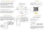
Page 3: ...Q_PDS_DM_09_V1 2 FiberGateway User Manual 3 ...

Page 4: ...tion or products referred to in the document This document is for information purposes only and does not constitute a legally binding offer The communication of the information contained in this document shall not oblige Altice Labs to supply the products and services identified and described herein Altice Labs reserves the right to effect changes to this document at any time and without prior not...

Page 5: ... 27 2 11 3 Interfaces and features 28 2 11 4 Data Rates 28 2 11 5 Antennas 28 2 12 Multiple QoS per VLAN 28 2 13 Policing Rate Limiting 29 2 13 1 Downstream QoS 29 2 13 2 Upstream QoS 30 2 13 3 Dynamic Bandwidth Allocation DBA 30 2 13 4 Upstream QoS scenarios 32 3 General Specifications 33 3 1 Interfaces 33 3 1 1 GPON 33 3 1 1 1 Optical Interfaces 33 3 1 2 Ethernet 34 3 1 3 FXS 35 3 1 4 Wi Fi 36 3...

Page 6: ...6 Contents 4 6 FiberGateway Setup 49 4 6 1 Network Provider Connection 50 4 6 2 Mains connection and power up 51 5 Configuration 53 5 1 FiberGateway Activation 53 5 2 Costumization 53 5 2 1 Software download from the OLT 53 6 Troubleshooting 55 ...

Page 7: ...N architecture 23 Figure 7 TR 142 Framework 23 Figure 8 FiberGateway system architecture 24 Figure 9 FiberGateway circuit block diagram 27 Figure 10 Dowstream QoS diagram 29 Figure 11 Upstream QoS diagram 30 Figure 12 Traffic distribution by service client 31 Figure 13 Wavelength planning 40 Figure 14 FiberGateway connectivity general view 43 Figure 15 FiberGateway Status LEDs 45 Figure 16 FiberGa...

Page 8: ......

Page 9: ...3 Table 4 FXS interface specifications 35 Table 5 Wi Fi specification 36 Table 6 General Features 37 Table 7 Standards compliance 41 Table 8 FiberGateway connectivity description 43 Table 9 LEDs Status information 45 Table 10 LEDs Status information PON LINK PON AUTH 46 Table 11 FiberGateway connections description 49 Table 12 Material required for instalation 49 Table 13 Troubleshooting Procedure...

Page 10: ......

Page 11: ...FS Common Internet File System CLI Command line interface CO Central Office CPE Customer Premises Equipment CRC Cyclic Redundancy Check DC Direct Current DDNS Dynamic DNS DHCP Dynamic Host Configuration Protocol DNS Domain Name System DSCP Differentiated Services Code Point DSL Digital Subscriber Line EAP SIM Extensible Authentication Protocol Method for GSM Subscriber Identity Module FTP File Tra...

Page 12: ...way Control Protocol MRU Maximum Receive Unit MTBF Mean Time Between Failures NAS Network Access Server NAT Network Address Translation NGN Next Generation Network NMS Network Management System OLT Optical Line Terminal OMCI ONT Management Control Interface ONT Optical Network Terminal OPEX Operational Expenditure OSI Open Systems Interconnection PC Personal Computer PON Passive Optical Network PP...

Page 13: ...ion Multiple Access TKIP Temporal Key Integrity Protocol TR 069 Technical Report 069 TTL Time to Live TV Television UDP User Datagram Protocol URL Uniform Resource Locator USB Universal Serial Bus UTP Unshielded Twisted Pair VAD Voice Activity Detection VAP Virtual Access Point VID VLAN Identifier VLAN Virtual Local Area Networks VoIP Voice over Internet Protocol VPN Virtual Private Network WAN Wi...

Page 14: ......

Page 15: ...e the receiving antenna Increase the separation between the equipment and receiver Connect the equipment into an outlet on a circuit different from that to which the receiver is connected Consult the dealer or an experienced radio TV technician for help This device meets the FCC requirements for RF exposure in public or uncontrolled environments RF Exposure Statement Note This transmitter must not...

Page 16: ......

Page 17: ...er with the support for bit rates of up to 2 5 Gbps downstream and 1 24 Gbps upstream an optical network splitting ratio of up to 1 64 in a single fiber and a distance range of up to 60 km make the GPON technology and the FiberGateway the most efficient option for passive optical network topologies when integrated service delivery is an issue Together with multi vendor OLT interoperability BBF 247...

Page 18: ......

Page 19: ... and deliver to premises domain the full broadband service pack Broadband service applications are commonly referred as below High speed internet HSI Voice VoIP services SIP MEGACO H 248 TV IPTV Wi Fi The multiplay environment is thus reinforced when combining the upper referred services 2 2 FiberGateway Application Scenario The next figure shows a possible gateway scenario for FiberGateway equipm...

Page 20: ...ervices configuration and management is achieved by means of the TR 069 protocol as defined by Broadband Forum This procedure takes for granted that previously the link layer connectivity has been achieved TR 069 is then transparent to the OLT since the TR 069 connections are established between the ACS and the ONTs Figure 4 ONT gateway family equipments integrate gateway functionalities Link laye...

Page 21: ...ve optical network in which unpowered optical splitters are used to enable a single optical fiber to serve multiple premises typically 1 64 A PON consists of an optical line terminal OLT at the central office and a number of optical network terminals ONT at the customer premises Downstream signals are broadcasted to all premises sharing multiple fibers Encryption can prevent eavesdropping Upstream...

Page 22: ...d video services Two FXS ports which can be connected to telephone sets to provide VoIP services Four Wi Fi antennas which can connect to Wi Fi terminals wirelessly to provide a secure and reliable high speed wireless network One USB port which can be connected to a USB storage device to provide convenient storage and file sharing services within a home network The communication between client equ...

Page 23: ...Report which defines a framework for the remote configuration and management of IP based services over PON Passive Optical Network and fiber access technology TR 142 framework uses TR 069 which is the protocol of choice for the remote management and configuration of IP services over PON and fiber access networks TR 069 is intended to be used for the remote configuration and management of IP servic...

Page 24: ...velengh with 2 488Gbps downstream and 1 244Gbps upstream by using an SC APC protected optical connector 2 8 Ethernet Ethernet is the wired LAN technology and is revised in the IEEE 802 3 standard At the OSI reference system Ethernet is at the Data Link layer In the FiberGateway equipment both WAN and LAN type of physical interfaces are 10 100 1000BASE T AUTO MIX Ethernet type over RJ45 conectors 2...

Page 25: ...ations over OMCI messages or could be downloaded FTP from the OLT up to the FiberGateway after its registration on the PON network FiberGateway equipments have the ability to deliver the Voice service over two types of interface 2 10 2 1 Logical interface VLAN encapsulation If the FiberGateway has no FXS ports and the VoIP service is transparently forwarded from the OLT up to the Home Gateway and ...

Page 26: ...e FiberGateway SW through download from the OLT via OMCI The FiberGateway equipment has a DHCP client to get an IP address alternatively the FiberGateway could be configured with a static IP The configuration of the static IP or DHCP client is related to the WAN side and is enabled by the OLT 2 11 Wi Fi 2 11 1 FiberGateway Block Diagram FiberGateway circuit block diagram is presented in the figure...

Page 27: ...tion The FiberGateway supports Wi Fi with Wi Fi interfaces operating in the 2 4GHz and 5GHz frequencies The FiberGateway complies with the following standards IEEE 802 11a 5GHz up to 54 Mbps IEEE 802 11b 2 4GHz up to 11 Mbps IEEE 802 11g 2 4GHz up to 54 Mbps IEEE 802 11n 2 4GHz and 5 GHz up to 600 Mbps IEEE 802 11ac 5GHz up to 1733 Mbps ...

Page 28: ...amic frequency selection DFS 4x4 with weather radar detection Multi User MIMO for better performance per user 2 11 4 Data Rates 802 11a 6 9 12 18 24 36 48 54 Mbps 802 11b 1 2 5 5 11 Mbps 802 11g 6 9 12 18 24 36 48 54 Mbps 802 11n up to 600 Mbps 802 11ac up to 1733 Mbps 1024QAM 2 4GHz up to 1000 Mbps 1024QAM 5GHz up to 2166 Mbps 2 11 5 Antennas 4x4 MIMO antennas Internal antennas with 4 5dBi antenn...

Page 29: ...by one or two tags It is remarked and policed per CoS rate port profile After this Network services per VLAN classification determine the PON port queue where packets will wait for a transmission opportunity and can remark the CoS P bits in VLAN PCP The traffic is put in a queue according with the p bit DSCP Traffic Class mapping Each of these Traffic Classes is associated with a scheduler WRR or ...

Page 30: ...st In the OLT PON ingress port traffic is remarked and can be policed per CoS The traffic is put into a Traffic Class according with what is defined in the p bit DSCP queue mapping Each of these Traffic Classes has an associated scheduler and policer Queue management is performed based on Tail Drop or WRED Then Traffic Classes to P bit remarking is done and the traffic is sent to the uplink Figure...

Page 31: ...5 RF5 RA5 b s Bandwidth Eligibility 0 0 Non Assured BW RNA Best Effort RBE RNA RBE In each GPON interface there are 1024 Alloc ID T CONT identifiers available provided to manage ONT services They are distributed in the following way Table 2 Alloc ID s distribution by T CONT type Alloc ID Allocation Type 0 127 Default Alloc ID Dynamic or Static 128 255 Reserved 256 639 Dynamic or Static 640 1023 St...

Page 32: ... 32 Technical Description 2 13 4 Upstream QoS scenarios 8 priority queues Strict priority Upstream Scheduling o Strict Priority currently supported o Strict Priority rate controller currently supported o Strict Priority WFQ can be SW supported ...

Page 33: ...ing wavelength nm 1260 1360 1260 1360 Line code Scrambled NRZ Scrambled NRZ Minimum ORL of ODN dB 32 32 Mean launched power MIN dBm 0 5 0 5 Mean launched power MAX dBm 5 5 Launched optical power without input to the Tx dBm Less than Min sensitivity 10 Less than Min sensitivity 10 Maximum Tx Enable 16 16 Maximum Tx Disable 16 16 Extinction ratio dB 8 2 8 2 Tolerance to the Tx incident light power d...

Page 34: ...ernet type over RJ45 connectors 1 ONT RX 8 30 dBm The equipment sensitivity assumes the use of the optional RS 255 239 FEC capability of the G PON TC layer with the current class B ONU detector technology The ONU overload is set at 8 dBm to be common with the class B value even though in this application 10 dBm is sufficient Optical solution B and C Connector type SC APC IEC 60825 1 Class 1 Laser ...

Page 35: ...istics A 25 mA max Hook flash on hook register recall hook flash 150 msec Minimum time of recognition of on hook when hook flash feature does not exist on hook register recall hook flash 1100 msec Minimum time on hook recognition when hook flash feature does exist off hook 40 msec minimum time off hook recognition interval 300 msec 1100 msec Time calibrated break pulse duration for register recall...

Page 36: ...nnel Bandwidths 20MHz and 40MHz channels in the 2 4GHz band 20MHz 40MHz 80MHz and 160MHz channels in the 5GHz band MIMO 4x4 MCS Supported values 0 31 and 32 for 802 11n 0 9 for 802 11ac Proprietary 10 11 1024QAM Wireless Security WEP 40bit secure key and 24 bit as defined in 802 11 2007 WPA WPA2 AES encryption de encryption coupled to TKIP as defined in 802 11 2007 and 802 1X Short Guard Interval ...

Page 37: ...0 80MHz 80 dBm M9 20MHz 58 dBm M9 40MHz 55 dBm M9 80MHz 52 dBm 3 2 General Features Table 6 General Features Features FiberGateway GPON 1x Singlemode Optical Fiber Cable SC APC Connector Ethernet 10 100 1000Base T 4x Ethernet UTP CAT5E direct or crossover AUTO MDIX cable RJ45 FXS Ports 2x voice fax RJ11 connector USB Ports 1x USB 2 0 Wi Fi 802 11a b g n ac Yes ON OFF button Yes RESET button Yes OL...

Page 38: ...S Downstream and FEC Downstream and Upstream Bitrates 2488 Gbps downstream 1244 Gbps upstream Class B optics 28 dB T CONT 32 GEM Port IDs 32 L2 L3 layer VLAN ID to GEM port ID mapping per WT 156 N 1 VLAN 1 1 Transparent VLAN Classification IDSCP TOS 802 1p TCI VLAN ID MAC address Traffic Management up to 8 queues per T CONT in Priority controlled mode or up to 16 queues per T CONT in Rate controll...

Page 39: ...er from the OLT in 1490nm and reports this value through OMCI The accuracy of the measurement is 3dBm maximum Optionally FiberGateway has also the chance to have an embedded optical reflective component in order to increase the FTTH probing capabilities in a 50 centimeters resolution factor which turns to have a single probing system to probe all GPON network ONTs even when its number increases ov...

Page 40: ...erminal equipments namely XOLT and XONT and by replacing the current WDM filter by the new one in order to handle the new XGPON signals XGPON must support emulate all GPON legacy services in case of total migration Like GPON XGPON is required to support triple play services data voice and video as well as mobile backhauling accurate frequency phase time synchronization application through its high...

Page 41: ...ware updates image system and the ability of back up allowing the SINGLE PORT FiberGateway start in case the software download fails to enable a new software update 3 7 Standards Table 7 Standards compliance EMC Emissions FCC CFR 47 Part 15 Subpart B Section 15 107 Conducted Emissions Class B FCC CFR 47 Part 15 Subpart B Section 15 109 Radiated Emissions Class B Radio 2 4 GHz FCC CFR 47 Part 15 Su...

Page 42: ......

Page 43: ...us LEDS information push buttons are located at the front side of the equipment Figure 17 Figure 14 FiberGateway connectivity general view Table 8 FiberGateway connectivity description Number Name Description 1 RESET Configuration RESET button 2 TEL 1 2 2x RJ11 FXS Ports 3 LAN 1 2 3 4 4x RJ45 Ports 10 100 1000Base T Ethernet with AUTO MDIX 4 USB 1x USB 2 0 port 5 ON OFF button ...

Page 44: ...tton Switches on off Wi Fi if pressed for 5 seconds With the Wi Fi interface on in order to connect a device the interface pressing the WPS button for 1second will start the association process 9 INFO Energy saving button In order to verify the status of all LEDS press the button If not pressed only POWER and Radio Signal LEDs WPS WIFI 5G and WIFI2 4G have updated status information ...

Page 45: ...atus information LED Identification LEDs Status Description A1 a A4 1 LAN ON With Ethernet connection green OFF No Ethernet connection Flashing Ethernet IN OUT activity green A5 1 INTERNET ON With Internet connection green OFF Inactive port Flashing Internet IN OUT activity green A6 1 PON LINK See table bellow A7 1 PON AUTH ...

Page 46: ...se status LEDS are always update pressing INFO button is not required Table 10 LEDs Status information PON LINK PON AUTH ONT FiberGateway 4x4 Status LEDs Status Description PON LINK PON AUTH 1 Initial OFF OFF Initial Status 2 Standby Flashing Flashing ONT is waiting for initial configuration by the OLT 3 Serial Number Flashing Flashing The OLT is configuring the ONT 4 Ranging Flashing Flashing ONT...

Page 47: ...ode Optical Cable with SC APC Connector GPON W1 Wi Fi 4 4 Before installing the FiberGateway equipment 4 4 1 Safety Warnings Check for site s environmental conditions and look for power and optical access points nearby Do not install the device in environments where the temperature or humidity exceeds the standard limits This device is a passive cooling device To prevent equipment overheating do n...

Page 48: ...should be observed FiberGateway front side should be oriented towards the area where the wireless network is to be used FiberGateway installation place should be at least 1 meter high and without o Interference sources nearby such as Microwave ovens DECT 2 4 GHz phones Audio Video transmitters Bluetooth equipment Baby Monitors etc o Obstacles such as walls stairs ceilings doors Metal Objects Windo...

Page 49: ...ing the WPS button for 1second will start the association process 9 INFO Energy saving button In order to verify the status of all LEDS press the button If not pressed only POWER and Radio Signal LEDs WPS WIFI 5G and WIFI2 4G have updated status information 4 6 FiberGateway Setup FibeGateway is intended to be installed on a flat surface The following table identifies the set of materials that may ...

Page 50: ...APC Figure 18 b and Optical connector cleaning material will be required Figure 18 Network provider connection Clean the optical connectors of the optical pactchcord Figure 18 b of the equipment PON port Figure 18 a and the optical wall socket Figure 18 before connecting using appropriate optical connector cleaning material Plug one of the patchcord cleaned SC APC optical connectors on the FiberGa...

Page 51: ...imum bend radius 4 6 2 Mains connection and power up Connect the power adaptor output connector to the 12 VDC power port on the equipment Plug the power adaptor appropriate power cord into an approved 100 to 230 VAC outlet Figure 16 Switch on the equipment ON OFF button After executing a power up sequence the equipment will be ready for operation ...

Page 52: ......

Page 53: ...t is loaded and executed Active if it is loaded and it is being executed in the FiberGateway There can be only one active image and only one committed image at a given moment The FiberGateway goes through a series of states in order to download and activate a software image Each state is defined according to the states of the variables of both images The OLT controls the FiberGateway state through...

Page 54: ...and executed by default when the FiberGateway is restarted Composition of the Software Image o A software image is divided into sections of 31 bytes with one section per OMCC message and each section protected by the CRC of the OMCC A group of sections makes up a window and a group of windows constituting the image ...

Page 55: ...ctly connected Check that the ETHERNET cable is properly connected to the equipments ETHERNET port Change the ETHERNET cable Check that the equipment connected to the ONT on thisEthernet port is switched ON PON LINK A7 OFF Anomaly in the optical fiber signal Check that the optical cable is correctly inserted in both the equipment s internal optical connector and the optical socket Check if the opt...

Page 56: ...Rua Eng José Ferreira Pinto Basto 3810 106 Aveiro Portugal Tel 351 234 403 200 Fax 351 234 424 723 ...

Reviews: