background image

ALTER ELETTRONICA s.r.l.

15033 Casale Monferrato (AL) – ITALY
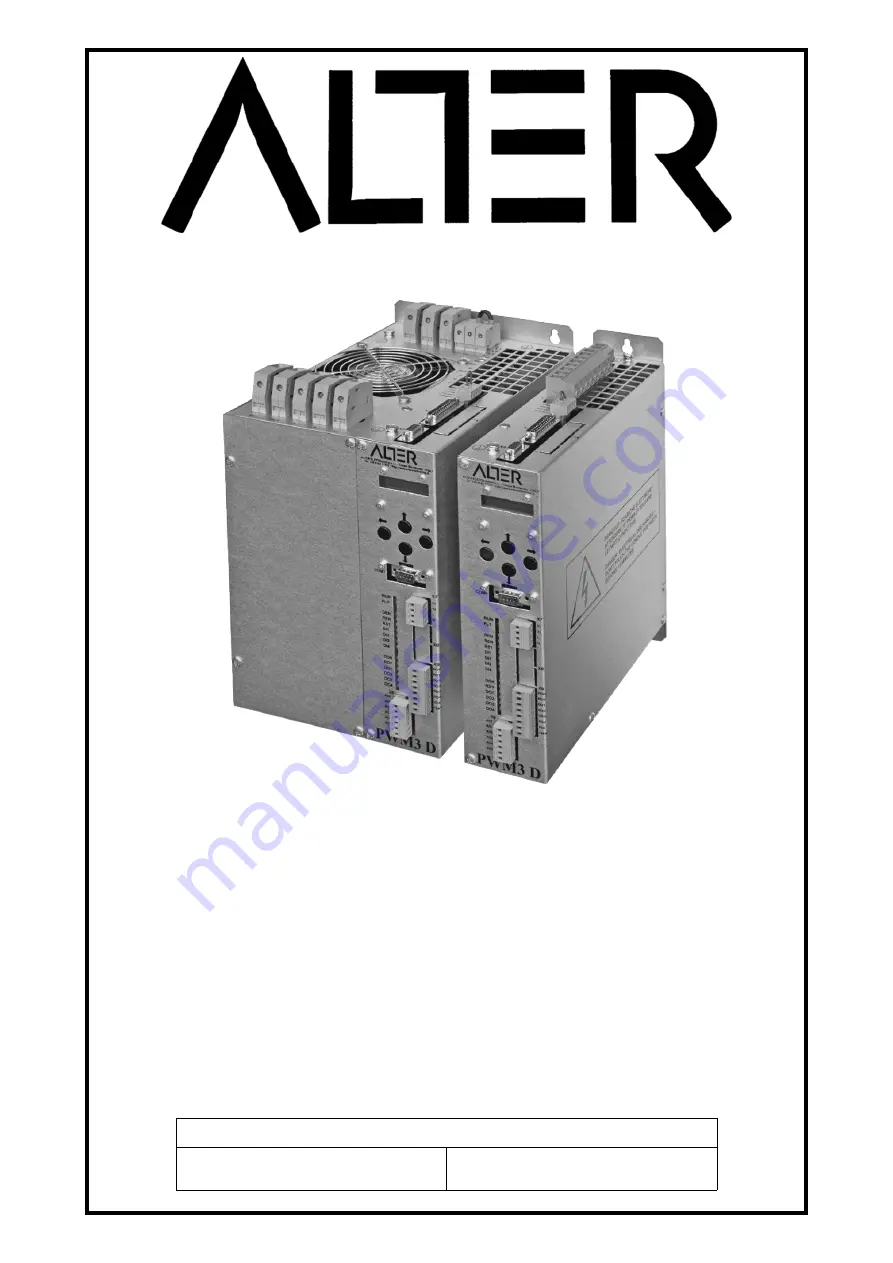
PWM3D-001

PWM3D-011

Drive 4 quadrants series PWM Digital

For brushless and DC motors with transducer 

Instructions 

Instructions 

manual

manual

91/121

91/121

 - Version 

 - Version 

6.3

6.3

 - Date: 

 - Date: 

17/11/2021

17/11/2021

Compatible with Firmware V

Compatible with Firmware V

6.x

6.x

Combined with the drive:

Type No.: ___ 

___ ___ ___

Serial No.: ___ ___ ___ ___ ___

Summary of Contents for PWM3D-001

Page 1: ...WM Digital For brushless and DC motors with transducer Instructions Instructions manual manual 91 121 91 121 Version Version 6 3 6 3 Date Date 17 11 2021 17 11 2021 Compatible with Firmware V Compatib...

Page 2: ...ections 13 4 4 Signal connections 14 4 5 Commands starting sequence 20 4 6 Commands shutdown sequence 20 4 7 Restarting after an alarm 21 5 Commissioning 22 5 1 Menu structure 22 5 2 Navigation in the...

Page 3: ...must be disconnected before any maintenance is carried out Before starting inspection please wait at least 2 minutes after switching off voltage make sure the LEDs and LCD display are switched off Ma...

Page 4: ...ws in force in the country where the drive is installed Appropriate preparation must be given to operators and machine operators The drive can cause radio frequency interference if it lacks the approp...

Page 5: ...utput drive 10 Maximum current peak dispensable from the drive 2 2 Declaration of conformity The ALTER Elettronica S r l declares that in the conditions specified in this document the drives CDM model...

Page 6: ...21Arms 033 33Arms 041 41Arms 050 50Arms 066 66Arms 080 80Arms 090 90Arms 100 100Arms 118 118Arms 200 200Arms 440 440Vac 480 480Vac 001 Generic BRUSHLESS motor control 011 Generic BRUSHLESS motor cont...

Page 7: ...L1 L2 L3 A B C Rest R X3 X6 X7 X9 X10 X11 X12 2 3 8 5 10 1 150 RES32R1KW5 23 020 17 001 16 684 2 5 2 5 1 5 13 8 16 1 150 RES32R1KW5 23 020 17 001 20 684 4 2 5 1 5 18 10 20 1 150 RES20R900W10 23 020 17...

Page 8: ...of the drives V I u Pa 1 73 V a The apparent power and current value thus calculated are valid only if the motors always work under the conditions considered in the calculations during normal operati...

Page 9: ...d signal adjustable between 1 mSec and 65 5 sec enabled by logical control Opto isolated logical inputs command from 15 to 30Vcc 10mA max Enable drive Speed ramp enable Alarm reset command 4 programma...

Page 10: ...rk and the drive a three phase inductance of at least 100 uH sized for the current absorbed by the drive and having a saturation current equal to at least twice the rated current see Drawing 1 on page...

Page 11: ...1 121 V6 3 Installation 4 Installation Drawing 1 Connection to a three phase power line PWM3D 001 only NOTE A DC motor shall be connected between terminals A and C Terminal B shall remain empty Alter...

Page 12: ...cient free space above and below for good cooling air circulation Use unpainted sheet fixing panels connected to the ground Connect to a good ground the ground terminal placed on the right side of the...

Page 13: ...g 1 on page 11 and in Drawing 2 on page 12 see table 2 on page 7 Connect the thermal probe as indicated in Drawing 1 on page 11 or Drawing 2 on page 12 only if the signal is not available on the trans...

Page 14: ...nection the three phase power supply locks L1 L2 L3 must be the same for all drives and must be supplied and removed simultaneously using a single contactor or multiple con trolled contactors at the s...

Page 15: ...UL5 and UL7 C B A E A J F M K C P D L H R C V series UL5 and UL7 yel red blue E A J F M K C P D L H R C V series UL5 and UL7 3 2 1 1 2 7 8 14 13 5 4 11 10 9 PTC PTC Signals U V W 5V V A A B B SE1 SE2...

Page 16: ...able It is normally used to provide a voltage signal proportional to the motor torque 3 AO2 Analog output 2 programmable It is normally used to provide a voltage signal proportional to the motor speed...

Page 17: ...is therefore able to perform the com mands See also paragraph RDY Ready on page 69 3 DO1 Digital output 1 programmable It is normally used to signal Zero Speed i e that the motor is stationary 4 DO2 D...

Page 18: ...0V Output 10Vcc 5 5mA max 3 10V Output 10Vcc 5 5mA max 4 AI1 Main analog input hot pole 1 resolution 15 bit sign programmable which is normally used for speed reference Tensions between AI1 and A0V AI...

Page 19: ...e case near the connectors anchorages are available for screens see Mechanical characteristics page 78 Signal allocation to PINs 1 DEN Enable input of the drive If this command is missing the motor is...

Page 20: ...upply on the DC BUS if this mode has been selected see Drawing 2 on page 12 and menu Power supply from on page 53 After the charge of the capacitors on the DC BUS the RDY output switches to the ON sta...

Page 21: ...an alarm when the drive is enabled regularly the DOK output goes to the OFF state flashes the red FLT LED and the alarm message appears on the LCD display When the control system PLC or CNC detects th...

Page 22: ...As you can see the structure can reach up to 4 levels of depth and the various menus are grouped from a main menu Some menus can only be displayed when using a certain type of transducer or if an opti...

Page 23: ...ESOLVER POLE 0 TACHOGENERATOR V krpm 0 AUTOTUNE MODE Optional param menu at level 3 Feedback Phase 0 00 FDBK DIRECTION normal HALL Phase 0 HALL DIRECTION normal HALL INVERTED NO TACHO COMBIN 0 DRIVE P...

Page 24: ...Inp 1 Sign Normal An Inp 1 Value SPEED RAMP Time Sec 1 0 MEMO PARAMETERS menu at level 1 SAVE RESTORE I O CONFIGURE menu at level 1 ANALOG INPUTS menu at level 2 ANALOG INPUT 1 menu at level 3 An Inp...

Page 25: ...n Inp 2 Dest NotUsed An Inp 2 Gain 1 0000 An Inp 2 Offset 0 00 An Inp 2 Value ANALOG INPUT 3 menu at level 3 An Inp 3 Dest NotUsed An Inp 3 Gain 1 0000 An Inp 3 Offset 0 00 An Inp 3 Value ANALOG INPUT...

Page 26: ...menu at level 2 ANALOG OUTPUT 1 menu at level 3 An Out 1 Source Mot Torq An Out 1 Value An Out 1 Gain 1 0000 An Out 1 Offset 0 00 An Out 1 Abs True ANALOG OUTPUT 2 menu at level 3 An Out 2 Source Moto...

Page 27: ...ut 3 Value An Out 3 Gain 1 0000 An Out 3 Offset 0 00 An Out 3 Abs True ANALOG OUTPUT 4 menu at level 3 An Out 4 Source Bus Volt An Out 4 Value An Out 4 Gain 1 0000 An Out 4 Offset 0 00 An Out 4 Abs Tr...

Page 28: ...sed Dig Inp 2 Sign Normal Dig Inp 2 Value DIGITAL INPUT 3 menu at level 3 Dig Inp 3 Dest NotUsed Dig Inp 3 Sign Normal Dig Inp 3 Value DIGITAL INPUT 4 menu at level 3 Dig Inp 4 Dest NotUsed Dig Inp 4...

Page 29: ...al DIGITAL OUTPUT 2 menu at level 3 Dig Op 2 Source MotorBrk Dig Op 2 Value Dig Op 2 Sign Normal DIGITAL OUTPUT 3 menu at level 3 Dig Op 3 Source MotorTmp Dig Op 3 Value Dig Op 3 Sign Normal DIGITAL O...

Page 30: ...DIAGNOSTIC menu at level 1 SPEED DEMAND SPEED ERROR SPEED FEEDBACK SPEED FEEDBACK RPM POSIT FEEDBACK MOTOR TORQUE DC BUS VOLTAGE V HEAT SINK TEMP C CAPACITOR TEMP C DSP TEMP C HALL SECT STATUS SE3 2 1...

Page 31: ...nor Resolver signal SinCos signal A and B SinCos signal C and D Man Offset Calc Disabled Serial comm status Internal alarm status Compatible encoder ADVANCED SETUP menu at level 1 ALTER MENU menu at l...

Page 32: ...menu at level 3 Threshold n 1 RPM 30 SPEED REACHED 2 0 EXT TORQUE LIMIT menu at level 3 TORQ LIM Source NOT USED LIMIT OUTPUT ANTI BACKLASH menu at level 3 AntiBack Mode Disabled CONTRAST TORQUE 0 0...

Page 33: ...utom Curr Lim Disabled MOTOR OVERTEMP menu at level 3 Signal Mode Dig Out Drive FLT delay Min 10 SUMMING BLOCK menu at level 3 Input 1 Input 2 Input 3 Input 4 Output Summ1 Output Summ2 Output Summ3 AN...

Page 34: ...USED An Ref 2 value 0 00 An Ref 2 dest NOT USED An Ref 3 value 0 00 An Ref 3 dest NOT USED An Ref 4 value 0 00 An Ref 4 dest NOT USED PID SPEED LOOP menu at level 2 Proport Gain P 10 00 Filter PB Pcom...

Page 35: ...parameter and after pressing the key you enter the change parameter mode that is identified by the appearance of a character in the bottom left corner of the display If there is the character in this...

Page 36: ...chnical office in case of request for advice or malfunctions Below is the explanation of the parameters that can be set from the menus divided into the various groups Quick Setup Group of menus that c...

Page 37: ...s parameter If the speed written on the motor plate is expressed in Radiants second Rad s the following formula may be used to calculate the corresponding speed in rpm RPM Speed RPM 9 55 Speed Rad s F...

Page 38: ...hall sectors relative to the motor rotor if it is known This parameter is optional and can be calculated automatic ally by the Autotune procedure Hall Direction Parameter displayed only with brushles...

Page 39: ...Gain 10 V MAX Vmax Maximum voltage of the speed reference Gain Gain of the analog input Substituting in the formula the bottom scale value of the example 8 5V is calculated that the gain to be set in...

Page 40: ...brought back to the situation of the last memorisation NOTE If it is necessary to return all the parameters to the factory values Global Reset the buttons and must be pressed simultaneously before sup...

Page 41: ...to compensate for any offset errors See Drawing 15 to figure out where this para meter works in the calculation An Inp 1 Sign This parameter is present only for the analog input AI1 With it you can s...

Page 42: ...s the same value as the parameter Value of the analog input 1 so it is not possible to define an exact scale as it de pends on the calibration parameters of the analog input 1 It is as if the calibrat...

Page 43: ...t Parameter that allows you to select the destination of the Value signal of the digital input The possible selections are NOT USED not used Rev Speed Ref sent to the ramp block to control the reversa...

Page 44: ...digital output indicates that the DC BUS has reached the right voltage and that the precharge of the capacitors is finished SPEED THRESH 1 the digital output standard on DO4 indicates that the motor h...

Page 45: ...f the temperature tends to be too high the causes may be due to lack of ventilation Capacitor Temp Indicates the temperature in degrees centigrade of the capacitors inside the drive This temperature m...

Page 46: ...1 12 The available statuses are FAULT serial communication problem with the encoder Check the status of the wires and connections on X14 pin 9 10 11 12 the shielding of the cable the presence of noise...

Page 47: ...see paragraph 5 6 10 on page 67 Speed Ramp Time Minimum Maximum Units of measure 0 1 650 0 Sec Parameter to set the up down time of the speed ramp Assuming an input of 0 to 100 of the value is given t...

Page 48: ...or Only signals from the motor trans ducer and the connection cable to the master drive must be connected to this drive MASTER 2 The anti backlash function TYPE 2 is active and the drive works as a MA...

Page 49: ...y at infinite time On a selectable digital output see paragraph Dig Op X source on page 44 you can send a signal to the CNC or PLC so that it can make the necessary decisions for this anomaly stop the...

Page 50: ...nalogue reference to be sent to the selected destination with the next parameter This value will be stored and will remain valid even after disconnecting the auxiliary services An Ref X dest Parameter...

Page 51: ...s with the Memo Parameters menu see page 40 and not before in this way it will always be possible to return to the previous situation Filter PB Pcomp Minimum Maximum Units of measure 0 100 00 This par...

Page 52: ...requency of this filter i e reduce the value to make the operation quieter Pi Current Loop Set of parameters to adjust the time constants of the PI adjustment loop on the current NOTE random change in...

Page 53: ...of an encoder equivalent to tracks A B and Z Position offset Minimum Maximum Units of measure 180 180 degrees This parameter allows to offset the position of the simulated encoder with respect to the...

Page 54: ...points Entered ALL motor data indicated in the previous paragraph Since the motor will rotate without the control of the external speed reference it is advisable to mechanically disconnect the motor...

Page 55: ...heck on the menu Diagnostic Speed Feedback RPM that the indicated speed is about equal to the one measured if it is not the same probably the transducer data that have been entered are incorrect 4 If...

Page 56: ...afert Selca T series old 6 2 3 4 2 3 2 6 1 11 7 9 10 Lafert Selca T series new 6 2 B C A 3 2 6 1 11 7 9 10 Lafert Selca T series new 6 2 V W U 3 2 6 1 11 7 9 10 Lafert Selca T series new 4 2 V U W 2 3...

Page 57: ...of the signal with the board 8 If all previous verifications are positive autotune of motor parameters can be performed as explained in paragraph Autotune for the synchronization of the transducer on...

Page 58: ...C and D and verify that there is OK otherwise perform these verifications Written LOW check that you ve connected the cable from both sides Check the cable and welding of wires on the X14 connector at...

Page 59: ...m status and verify that there is OK otherwise carry out these checks Written FAULT check that you ve connected the cable from both sides Check the cable and welding of wires on the X14 connector at p...

Page 60: ...series 120 V W U 8 2 4 6 1 12 11 10 9 3 5 7 BAUMULLER DS56 DS71 DS100 series 120 U V W 6 8 11 2 1 10 9 7 4 3 5 Drive SYSTEM BLT series 120 1 2 3 J D M K B A Z W N Lafert Selca T series old 120 W V U G...

Page 61: ...n are present If this does not occur please contact the ALTER Technical Office for some verifications 5 Scroll through the menu to the Quick setup Motor Parameters Tachogenerator parameter Set the vol...

Page 62: ...t the item Motor Brake see paragraph Dig Op X source on page 44 If you want to change the logical state of the brake control output you must insert or disconnect the logical reversal setting of the ou...

Page 63: ...u have to go to the configuration menu I O Configure Digital Outputs and from the selection menu of the source of the desired output go to select the item Peak Mot Load see paragraph Dig Op X source o...

Page 64: ...by one motor increases while that of the other diminishes keeping the play of the kinematic chain always null The anti backlash system uses two equal drives same rated current One drive is called Mas...

Page 65: ...ter by selecting SLAVE 5 Set the motor parameters on both the Master drive and the Slave drive one at a time following the instructions in paragraph Setting motor parameters on page 54 At the end of t...

Page 66: ...directions Generally a value of 5 to 30 is sufficient 19 If the axis has not a smooth motion you can use the MASTER 2 mode which uses a different algorithm At the end of all adjustments it is essenti...

Page 67: ...eference to drawing 23 we can find Input 1 4 It is the input signals to the block that come from the sources that have been selected These values are added to gether as shown in the drawing Disable Su...

Page 68: ...n the logical state of Inp Sel is at the logical level 1 the source signal of InputB is sent to output Out Using these analog selectors combined with other auxiliary functions you can create cus tom a...

Page 69: ...formation see the section Connector X12 on page 19 6 1 7 DI4 Digital Input 4 Display the status of the external command DI4 to control a certain programmable function associated with this input For mo...

Page 70: ...tore it and see if the message disappears Otherwise notify the ALTER Technical Service 6 4 3 Anti backlash data error This alarm only appears with the anti backlash function activated see section Anti...

Page 71: ...he resistance of the internal clamp to the drive has exceeded the temperature of 135 C The causes of the alarm are 1 High number of consecutive motor stops 2 Stop times too short 3 Load inertia too hi...

Page 72: ...eck the continuity and isolation of the connecting cable between the motor and the drive Check the status of the TERMINALS and their clamping Check the windings of the motor Reduce the proportional ga...

Page 73: ...r s operation 6 4 15 Heat sink Over Temperature This alarm appears when the heat sink temperature of the drive bridge is greater than that allowed The causes of the alarm are 1 Temperature inside the...

Page 74: ...or electrical connection on the terminals 6 4 22 Temper Sens Damaged This alarm appears when the drive detected a fault to a temperature sensor mounted inside it turn off the drive and notify the ALT...

Page 75: ...01 324 try turning the visible trimmer next to the X14 connector in the anticlockwise direction and give the alarm reset command RST to see if the message disappears SinCos board 01 325 check the wire...

Page 76: ...hen the mes sage appears it means that the PTC probe installed in the motor has just taken when the time set in the Drive FLT delay menu has elapsed see page 49 the drive will go in bulk motor tempera...

Page 77: ...mmand 69 RTD Reset Alarm reset command 69 DI1 Digital Input 1 Digital input control n 1 69 DI2 Digital Input 2 Digital input control n 2 69 DI3 Digital Input 3 Digital input control n 3 69 DI4 Digital...

Page 78: ...Mechanical characteristics Instruction manual 91 121 V6 3 8 Mechanical characteristics 8 1 Size 1 Mass 4 6 Kg 78 Alter Elettronica s r l Drawing 24...

Page 79: ...Instruction manual 91 121 V6 3 Mechanical characteristics 8 2 Size 2 Mass 12 Kg Alter Elettronica s r l 79 Drawing 25...

Page 80: ...Mechanical characteristics Instruction manual 91 121 V6 3 8 3 Size 3 Mass 14 Kg 80 Alter Elettronica s r l Drawing 26...

Page 81: ......

Page 82: ......

Page 83: ......

Page 84: ...Alter Elettronica s r l Alter Elettronica s r l Via Ezio Tarantelli 7 15033 Casale Monferrato AL ITALY Tel 39 0142 77337 Web http www alterelettronica it email...

Reviews: