ALLIANCE TENNA-ROTOR U-110, Manual
The ALLIANCE TENNA-ROTOR U-110 is a top-of-the-line antenna rotor system designed to enhance your TV reception. With its precise motor and durable construction, it allows you to effortlessly rotate and position your antenna for optimal signal strength. Download the free manual for the U-110 from manualshive.com and unlock the full potential of this high-performance product.
Share
Download


Reviews:
No comments
Related manuals for TENNA-ROTOR U-110
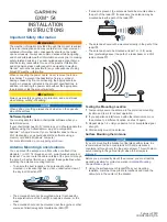
GXM 54
Brand: Garmin Pages: 4

SV-9310
Brand: One for All Pages: 40

BISCAYA AIS
Brand: RR Electronic Pages: 8

ANT 033
Brand: Williams Sound Pages: 4
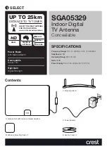
SGA05329
Brand: Crest Audio Pages: 4

DXE-MBVE-1
Brand: DX Engineering Pages: 32

11dBi
Brand: MAPLE WIRELESS Pages: 10

AP536
Brand: Antsig Pages: 2

SPEED 8 field Antenna
Brand: BENZING Pages: 2

SATMAR37
Brand: Majestic Pages: 19

GPSD Series
Brand: Panorama Antennas Pages: 2

WMM9G Series
Brand: Panorama Antennas Pages: 8

15-2160
Brand: Radio Shack Pages: 2

WS-6933
Brand: Satlink Pages: 10

124WB Boomer
Brand: CUSHCRAFT Pages: 4

AM-01/6
Brand: SPE Pages: 14

DMX, DMXMD, DMXHD
Brand: WADE Antenna, Inc. Pages: 2

ATG3G Series
Brand: YIC Technologies Pages: 7


