background image

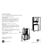
Installation/Operation

Stacked Washer/Dryers

Electric and Gas Models

SWD455C_SVG

Original Instructions
Keep These Instructions for Future Reference.
CAUTION: Read the instructions before using the machine.

(If this machine changes ownership, this manual must accompany machine.)

www.alliancelaundry.com

Part No. 805419R3

August 2017

Summary of Contents for SWD455C SVG

Page 1: ... Models SWD455C_SVG Original Instructions Keep These Instructions for Future Reference CAUTION Read the instructions before using the machine If this machine changes ownership this manual must accompany machine www alliancelaundry com Part No 805419R3 August 2017 ...

Page 2: ......

Page 3: ...yer user smells gas The gas utility instructions plus the SAFETY and WARNING note directly above must be posted in a prominent location near the dryer for customer use WARNING Installation of unit must be performed by a quali fied installer Install clothes dryer according to manufacturer s instructions and local codes DO NOT install a clothes dryer with flexible plas tic venting materials If flexi...

Page 4: ...ber or gas fitter This appliance must be installed with a 36 inch 910 mm long flexible gas connector A T Handle type gas shut off valve must be installed in the gas supply line to this appliance This appliance must not be installed in a bedroom or bath room Copyright Alliance Laundry Systems LLC DO NOT COPY or TRANSMIT 4 Part No 805419R3 ...

Page 5: ...t Electrical Plug 20 Earth Ground Information 20 Connecting Power Cord with Three Wire Plug 22 Connecting Power Cord with Four Wire Plug 24 Connect Dryer Exhaust System 26 Exhaust Direction 27 Exhaust System 27 Multi Dryer Installation Exhaust Requirements 28 Position and Level the Unit 30 Wipe Out Inside of Washer and Dryer Drums 31 Plug In the Washer and Dryer 32 Electric Dryer 32 Gas Dryer 32 W...

Page 6: ...oading Door 40 Determine Proper Controls 40 Set Fabric Selector 40 Insert Coins or Card 40 Start Dryer 41 Indicator Lights 41 Maintenance 42 User Maintenance Instructions 42 Lubrication 42 Cold Weather Care 42 Extended Non Use 42 Care of Your Washer 42 Care of Your Dryer 42 Reinstallation of Shipping Materials 43 Motor Overload Protector 44 For Energy Conservation 44 Troubleshooting 45 Contact Inf...

Page 7: ...by licensed personnel when required Do not do it yourself Do not install or store the washer where it will be exposed to water and or weather Do not add the following substances or textiles containing traces of the following substances to the wash water gasoline kerosene waxes cooking oils vegetable oils machine oils dry cleaning solvents flammable chemicals thinners or other flammable or explosiv...

Page 8: ... dealer distributor service agent or the man ufacturer about any problems or conditions you do not under stand Important Safety Instructions DRYER Save These Instructions WARNING To reduce the risk of fire electric shock serious in jury or death to persons when using your dryer fol low these basic precautions W130 Read all instructions before using the dryer Install this dryer according to the INS...

Page 9: ... and the exhaust duct should be cleaned periodically by qualified service personnel Do not repair or replace any part of the dryer or attempt any servicing unless specifically recommended in the user mainte nance instructions or in published user repair instructions that you understand and have the skills to carry out ALWAYS dis connect the electrical power to the dryer before attempting service D...

Page 10: ...6 9 in 938 mm I 14 6 in 371 mm J 32 in 813 mm K 26 875 in 683 mm L 78 17 in 1986 mm M 46 62 in 1184 mm N 2 04 in 52 mm O 27 73 in 704 mm P with door closed 1 5 in 38 mm Q 13 1 in 333 mm NOTE Exhaust openings are 4 inch 102 mm metal ducting With leveling legs turned into base For ADA compliance turn legs out from base 0 5 inches Dimensions Copyright Alliance Laundry Systems LLC DO NOT COPY or TRANS...

Page 11: ... mm I 36 9 in 938 mm J 14 6 in 371 mm K 44 87 in 1140 mm L 32 in 813 mm M 26 875 in 683 mm N 78 17 in 1986 mm O 46 62 in 1184 mm P 2 04 in 52 mm Q 27 73 in 704 mm R with door closed 1 5 in 38 mm S 13 1 in 333 mm NOTE Exhaust openings are 4 inch 102 mm metal ducting With leveling legs turned into base For ADA compliance turn legs out from base 0 5 inches Dimensions Copyright Alliance Laundry System...

Page 12: ...6 97 in 1447 mm C 23 5 in 597 mm D 8 375 in 213 mm E 24 in 610 mm F 8 in 203 mm G 15 4 in 391 mm H 2 3 in 60 mm I 36 9 in 938 mm J 14 6 in 371 mm K 44 87 in 1140 mm L 32 in 813 mm M 26 875 in 683 mm N 4 2 in 107 mm O 4 1 in 104 mm P 46 62 in 1184 mm Q 78 17 in 1986 mm R 2 04 in 52 mm S 27 73 in 704 mm Table continues Dimensions Copyright Alliance Laundry Systems LLC DO NOT COPY or TRANSMIT 12 Part...

Page 13: ...t left side of cabinet because of burner housing IMPORTANT The dryer should have sufficient clear ance around it for needed ventilation and for the ease of installation and servicing For maximum drying per formance we recommend that more clearance be al lowed around the dryer than the clearances that are listed throughout this manual Dimensions Copyright Alliance Laundry Systems LLC DO NOT COPY or...

Page 14: ...nit 1 Position unit near area of installation 2 Remove the shipping materials 3 Connect the fill hoses 4 For non gravity drain models connect the drain hose to the drain receptacle 5 For gravity drain models connect the drain outlet to the drain system 6 For gas models only connect the gas supply pipe Check for gas leaks 7 For electric models only connect the electrical plug 8 Connect dryer to exh...

Page 15: ...ear shipping bolt holes FLW2358N_SVG Figure 5 7 Replace front access panel 8 Save all shipping materials They must be reinstalled any time washer is moved more than four feet IMPORTANT Do not lift or transport unit from front or without shipping materials installed Refer to the Maintenace section for proper instructions on rein stalling the shipping materials Connect Fill Hoses WARNING Under certa...

Page 16: ...creens to water supply faucets 3 Connect the other hose couplings to the hot and cold valve connections at the rear of the washer 4 Thread hose couplings onto valve connections finger tight Then turn 1 4 turn with pliers IMPORTANT DO NOT cross thread or overtighten couplings This will cause them to leak 5 Turn water on and check for leaks 6 If leaks are found retighten the hose couplings 7 Continu...

Page 17: ...dging from drain receptacle during use SWD1026N_SVG 2 3 1 1 24 to 36 in 610 to 914 mm Recommended Height 2 Beaded strap from accessory bag 3 Standpipe 2 in 51 mm or 1 1 2 in 40 mm Figure 8 Gravity Drain Models Connect Drain Outlet to Drain System Maximum flow rate is 24 gallons minute 90 8 liters minute Flow rates will vary with load type 1 Remove drain fitting 4 inches 102 mm long and hose clamp ...

Page 18: ...ified service per son W316 1 Make certain your dryer is equipped for use with the type of gas in your laundry room Dryer is equipped at the factory for Natural Gas with a 3 8 inch NPT gas connection NOTE The gas service to a gas dryer must conform with the local codes and ordinances or in the ab sence of local codes and ordinances with the latest edition of the National Fuel Gas Code ANSI Z223 1 N...

Page 19: ...An 1 8 in NPT pipe plug must be installed as shown for checking inlet pressure Refer to Figure 10 D233I_SVG 2 3 4 1 5 1 New Stainless Steel Flexible Connector Use design CSA certified connector Use only if allowed by local co des 2 1 8 in NPT Pipe Plug 3 Equipment Shut Off Valve 4 Black Iron Pipe Shorter than 20 ft 6 1 m Use 3 8 in 9 5 mm pipe Longer than 20 ft 6 1 m Use 1 2 in 12 7 mm pipe 5 3 8 ...

Page 20: ...h ground in accordance with all lo cal codes and ordinances WARNING Improper connection of the equipment earth ground conductor can result in a risk of electric shock Check with a qualified electrician or service person if you are in doubt as to whether the dryer is properly connected to a protective earth ground W886 Do not modify the plug provided with the cord kit if it will not fit the outlet ...

Page 21: ... Figure 11 Three Wire Connection D679I_SVG 8 7 6 5 4 3 2 1 1 Ground Wire 2 Ground to Neutral Wire 3 Neutral Terminal 4 L2 Terminal 5 Center Wire Neutral 6 Strain Relief Not supplied with dryer 7 Ground Screw 8 L1 Terminal Figure 12 Installation Copyright Alliance Laundry Systems LLC DO NOT COPY or TRANSMIT 21 Part No 805419R3 ...

Page 22: ... for new branch cir cuit installations mobile homes or where codes do not permit grounding through neutral NOTE The power cord is NOT supplied with the elec tric dryer Type of power cord and gauge of wire must conform to local codes and instructions The method of wiring the dryer is optional and subject to local code requirements NOTE Connect the dryer to the power supply with the MAXIMUM RATED VO...

Page 23: ...ice Entrance Switch Box Refer to NOTE above 8 30 Ampere Fuses or Circuit Breaker 9 Neutral Wire 10 Metallic or Non Metallic Sheathed Cable Copper Wire Only 11 Power Cord Not supplied with dryer 12 Neutral 13 Terminal Block in Dryer 14 Intermediate Shut Off Box may or may not be fused 15 Direct Connection 16 Power Cord Connection Figure 14 1 Disconnect power to dryer 2 Remove access cover from rear...

Page 24: ...table indicating device connected to the center earth ground pin of the plug and the green screw on the back of the cabinet 8 Reinstall access cover and screw Connecting Power Cord with Four Wire Plug NOTE Four wire cord is required for new branch cir cuit installations mobile homes or where codes do not permit grounding through neutral DRY2016N_SVG 7 7 7 7 6 3 2 1 4 5 1 Typical Four Wire Receptac...

Page 25: ...ire to Neutral terminal NOTE When installing the white wire loop the free eyelet end of the earth ground to neutral wire re moved in Step 3 and attach along with the white wire to the neutral center terminal on the terminal block 7 Using a screwdriver tighten all screws firmly IMPORTANT Failure to tighten these screws firmly may result in wire failure at the terminal block 8 Secure the strain reli...

Page 26: ... To reduce the risk of fire due to increased static pressure we do not recommend installation of in line secondary lint filters or lint collectors If secon dary systems are mandated frequently clean the system to assure safe operation W749 IMPORTANT Installing in line filters or lint collectors will cause increased static pressure Failure to main tain the secondary lint system will decrease dryer ...

Page 27: ...ust dryer properly will void warranty A dryer will dissipate 60 Btu ft2 681 392 J m2 of surface area exposed to the conditioned air NOTE Venting materials are not supplied with the dry er obtain locally IMPORTANT DO NOT block the airflow at the bottom of the dryer s front panel with laundry rugs etc Blockage will decrease airflow through the dryer thus reducing the efficiency of the dryer Exhaust ...

Page 28: ...158 clause 7 3 2 A Multi Dryer Installation Exhaust Requirements Figure 24 shows a typical example of a multiple dryer installa tion Note how each dryer has its own exhaust system vented to the central exhaust duct SWD998N_SVG 4 3 2 1 1 58786 Backdraft Damper Available through your local authorized parts source 2 Clean Out Cover Must be provided Inspect monthly 3 Weather Hood or Sweep Elbow No cap...

Page 29: ... No Screen or Cap 5 24 in 610 mm Minimum Clearance to Roof Ground 6 Exhaust Outlet 7 Air Flow 8 30 9 Clean Out Cover Inspect Monthly Figure 25 Duct Station Minimum Diameter of Collector Duct A 4 inches 102 mm B 8 inches 203 mm C 9 inches 229 mm D 10 inches 254 mm E 11 inches 279 mm F 12 inches 305 mm G 13 inches 326 mm H 14 inches 356 mm I 15 inches 381 mm J 15 inches 381 mm K 16 inches 406 mm Tab...

Page 30: ...ill keep the exhaust air in balance within the central exhaust system Position and Level the Unit WARNING Units elevated above floor level must be anchored to that elevated surface base or platform The material used to elevate the unit should also be anchored to the floor to ensure that the unit will not walk or that the unit can not be physically pulled tipped or slid from its installed position ...

Page 31: ...nut and adjust legs by screwing into or out of unit base until the unit is level from side to side and front to back using a level Unit should not rock NOTE Leveling legs can also be adjusted from in side the unit using an adjustable wrench 6 Tighten the locknuts securely against the unit base If the locknuts are not tight unit will move out of position during operation NOTE DO NOT slide unit acro...

Page 32: ...the customer s responsibility to have the wiring and fuses installed by a qualified electrician to make sure adequate electrical power is available to the dryer W521 When plugging in the dryer DO NOT overload circuits DO NOT use an extension cord DO NOT use an adapter DO NOT operate both a washer and a gas dryer on the same circuit Use separately fused 15 Amp circuits The dryer is designed to be o...

Page 33: ...h ground prong from this plug W823 WARNING Improper connection of the equipment earth ground conductor can result in a risk of electric shock Check with a qualified electrician or service person if you are in doubt as to whether the dryer is properly connected to a protective earth ground W886 Do not modify the plug provided with the dryer if it will not fit the outlet have a proper outlet install...

Page 34: ...e slot effective earth ground receptacle rated 110 120 Volts AC alternating current 15 Amps Refer to Figure 32 to determine correct polarity of the wall recep tacle Standard 120 Volt 60 Hertz 3 Wire Effective Earth Ground Circuit DRY2022N_SVG 7 6 8 5 4 3 2 1 1 L1 2 Earth Ground 3 Neutral Side 4 Round Earth Ground Prong 5 Neutral 6 0 V A C 7 120 12 V A C 8 120 12 V A C Figure 32 WARNING To reduce t...

Page 35: ...Level the Washer to readjust leveling legs Check Heat Source Electric Dryers 1 Close the loading door and start the dryer in a heat setting re fer to the operation instructions 2 After the dryer has operated for three minutes the exhaust air or exhaust pipe should be warm Gas Dryers IMPORTANT This operation is to be conducted by qualified personnel only 1 To view the burner flame remove the lower ...

Page 36: ...Shutter Lockscrew 2 Air Shutter 3 1 8 in 3 1 mm Pipe Plug For checking manifold pressure 4 Shut off Valve Open Position 5 Shut off Valve Closed Position 6 Shut off Valve Handle Figure 33 Installation Copyright Alliance Laundry Systems LLC DO NOT COPY or TRANSMIT 36 Part No 805419R3 ...

Page 37: ...LICATES COLD cycle The cycle includes agitation and final spin speeds that maintain the load s balance and minimize wear to the articles NOTE Different fabrics will have different densities and loads must be adjusted accordingly to meet ma chine loading specifications shown Close Loading Door Close loading door tightly The washer will not operate with the loading door open FLW2310N_SVG Figure 35 A...

Page 38: ...AL COLD PERM PRESS WARM or DELICATES COLD cy cle Light indicates selection NOTE Changes can be made to Fabric Selector setting up until the first fill is complete FLW2361N_SVG NORMAL HOT PERM PRESS WARM NORMAL WARM NORMAL COLD DELICATES COLD START Figure 38 Insert Coins or Card To Insert Coins 1 Insert coin s in coin slot 2 Check pricing as seen on digital display W387I_SVG Figure 39 To Insert Car...

Page 39: ... a qualified service person refer to the wiring diagram located inside of washer control cabi net and check for broken loose or incorrect wiring NOTE Once a cycle has started the door can only be opened by first unplugging the power cord and waiting one minute WARNING To reduce the risk of bodily injury do not remove laundry from washer until all lights are out and all moving parts have stopped W0...

Page 40: ...032N_SVG Figure 44 Determine Proper Controls The direction of the arrow indicates which control is for which unit SWD960N_SVG Figure 45 Set Fabric Selector Select HIGH TEMP MED TEMP LOW TEMP or DELICATES by pushing touchpad NOTE Always follow manufacturer s care labels DRY1926N_SVG Figure 46 Insert Coins or Card To Insert Coins 1 Insert coin s in coin slot 2 Check pricing as seen on digital displa...

Page 41: ...mperature that ensures that the items will not be damaged WARNING To prevent the risk of fire never stop a dryer before the end of the drying cycle unless all items are quickly removed and spread out so that the heat is dissipated W756 Indicator Lights START START is lit whenever the dryer is not in a cycle the full vend price has been satisfied and the dryer door is closed When the START pad is p...

Page 42: ...lowing surfaces should be wiped off periodically The outside perimeter of the door glass where the seal con tacts the glass The front surface of the door seal lip Usually a mild soap solution will work If there is an extreme build up of minerals from a hard water supply the surfaces may need to be cleaned with a lime removal chemical Replacing Hoses Hoses and other rubber parts deteriorate after e...

Page 43: ... maintenance is not covered under the terms of the warranty The weather hood should be checked frequently to make sure the dampers move freely dampers are not pushed in and that nothing has been set against them Keep dryer area clear and free from combustible materials gaso line and other flammable vapors and liquids Do not obstruct the flow of combustion and ventilation air NOTE Verify proper ope...

Page 44: ...ad dryer Do not overdry clothes Remove items to be ironed while still damp Large loads of similar fabrics dry the most efficiently How ever dry permanent press in smaller loads to prevent wrin kling Use the correct temperature FABRIC SELECTOR setting for the type of fabric being dried Locate your dryer so the exhaust duct is as short and straight as possible Do not open the door during the drying ...

Page 45: ... only Make sure door latch is properly adjusted relative to door lock Won t Spin Tumble Make sure power cord is plugged all the way into the electrical outlet Check the laundry room fuse or circuit breaker Make sure that the controls are properly set Press START keypad Make sure that the loading door is closed tightly Broken drive belt Call the service person Foreign object trap in pump may be clo...

Page 46: ...ly Make sure washer is level Uneven leveling can cause vibration Make sure washer is installed on a solid sturdy and level floor The washer should not be installed on carpeting soft tile a platform or other weakly supported structures Make sure rubber feet are installed on all four leveling legs Refer to Position and Level the washer Is Noisy Make sure washer is level Uneven leveling can cause vib...

Page 47: ... room fuse s isn t blown or loose or circuit breakers aren t open The dryer itself does not have an electrical fuse An electric dryer has an electrical circuit with two fuses Make sure controls are in a HEAT setting Gas dryer only Make sure equipment and main gas line valve is turned on Check exhaust duct to outside to see if it is kinked blocked or needs cleaning Check weather hood to make sure f...

Page 48: ... sounds include the heat source going on and off and the humming of air moving through the dryer and exhaust system Clothes are too wrinkled Check heat setting Overdrying can cause wrinkling Check load size Large loads may not tumble properly and may cause wrinkling Clothes have odor Check room for odors before drying clothes Any odor fried foods paint varnish cleaners burning wood etc will trans ...

Page 49: ...Date Purchased Table continues Model Number Serial Number Please include a copy of your bill of sale and any service receipts you have WARNING To reduce the risk of serious injury or death DO NOT repair or replace any part of the unit or attempt any servicing unless specifically recommended in the user maintenance instructions or in published user repair instructions that you understand and have t...

Page 50: ...yer Drums SWD1030N_SVG CHECK CHECK 4 Connect Drain Hose to Drain Receptacle or Drain Outlet to Drain System SWD1026N_SVG1 SWD1002N_SVG1 10 Plug In Washer and Dryer DRY2669N_SVG CHECK CHECK 5 GAS ONLY Connect Gas Supply Pipe Check for Gas Leaks D233I_SVG1 11 Recheck Steps CHECK CHECK 6 ELECTRIC ONLY Con nect Electrical Cord D679I_SVG1 12 Start and Run Dryer in Heat Setting to Verify Dryer is Heatin...

Reviews: