


Copyright © 2012 Alarm.com
|
www.alarm.com
|
v2.0
1
NetworX CDMA Module
|
Installation Guide
NetworX CDMA Module
INSTALLATION GUIDE
Introduction
Alarm.com’s CDMA module can be used on NetworX 4V2, 6V2, 8V2, and 8E
panels. The module interfaces with the NetworX panel data bus and is
powered by the panel. The Alarm.com bus module for NX is made of two
parts: A bus module (NX-592E) that connects to the panel via 3 bus wires,
and the CDMA radio daughter board that plugs onto the NX Gateway board.
The CDMA radio daughter board is the only new part.
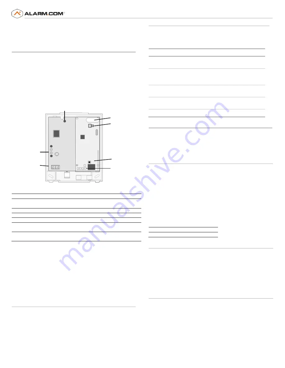
Figure 1
and
Table 1
describe the components’ function and location.
Figure 1: NX-592E Gateway bus module, with CDMA radio daughter board on
the right (in gray).
Table 1: Components description
Component
Function
Bus LED
Indicates data bus activity between the panel and the
bus module.
Gateway status LEDs
Not used.
Wiring terminals
Provides wiring connection to the panel.
Antenna jack
Antenna connection for wireless data transceiver.
Radio Status LEDs
Indicates communication with the CDMA network,
report errors, and signal strength.
Serial number
A 15-digit number. Only the last 10 digits are used for
account activation.
NOTE:
You do not need to reference the Status LEDs on the left side of the bus
device. Refer instead to the CDMA Status LEDs at the bottom of the radio.
CAUTION:
THE NX-208E TWO WIRE SMOKE EXPANDER MODULE IS NOT
COMPATIBLE WITH ANY MODEL VARIANT OF THE INTERLOGIX NX-592E-XX
NETWORX CELLULAR MODULE OR THE ALARM.COM EVDT2-ZD-P6-B1-N-XX
CELLULAR MODULE. THE NX-208E AND ANY MODEL VARIANT OF THE
INTERLOGIX NX-592E-XX NETWORX CELLULAR MODULE OR THE ALARM.COM
EVDT2-ZD-P6-B1-N-XX CELLULAR MODULE SHOULD NOT BE INSTALLED
WITHIN THE SAME SYSTEM.
Installation Tips
Use the following tips to help guarantee your success with the Alarm.com
NetworX CDMA Module:
1)
Make sure you create the customer account on the Alarm.com dealer
website at least 24 hours before installation.
2)
Use the Radio Status LEDs on the module to check the signal strength
before you permanently mount the module.
3)
Do a phone test to initiate communication (see
Power up
on page 2).
Status LEDs
Figure 1
shows where the radio status LEDs are on the module and
Table 2
describes the LED functions. See
Radio Status LEDs
on page 3 for more
information.
Table 2: LED Functions
LED
Function
L1
Error LED. Flashes 1 to 8 times in an 8-second interval to indicate
specific error. See
Table 5
for errors and common fixes.
L2
Panel Communication and Z-Wave status messages. Flashes every
time the module communicates with the panel and flashes in
patterns to indicate Z-Wave status.
L3
CDMA Communication. Flashes every time the CDMA signal level is
checked and when packets are exchanged with Alarm.com.
L4
CDMA Signal Level. Flashes 0 to 5 times to indicate signal strength, or
toggles on/off slowly when communicating with Alarm.com servers.
L5
Z-Wave Error LED. See
Table 6
for error descriptions.
Installation
Before you install the system, the module must be activated (see
Account
Creation
on page 5). The account creation process automatically activates
the module within 24 hours. Installation consists of finding a good mounting
location for the module to optimize wireless signal strength, mounting the
module, wiring the module, and installing a case tamper (if necessary).
Installation Guidelines
Use the following installation guidelines:
•
The module draws a maximum of 65 mA (continuous) in PowerSave
mode and 100 mA (continuous) in Idle Mode and Connected Mode
from the panel. The module can draw up to 1600 mA (instantaneous
peaks) from the panel.
•
Do not exceed the panel total output power when using panel power
for bus devices and hardwired sensors (refer to your panel
documentation).
•
Use three-conductor, 22 or 18 gauge stranded wire to connect the
module to the panel.
Table 3
shows the maximum wire length for each
gauge.
Table 3: Maximum wire length
22 gauge
40 ft. (12.2 m)
18 gauge
90ft. (27.4 m)
Tools and Supplies Needed
You will need the following tools and supplies:
•
Small blade and Phillips screwdriver.
•
Drill and bits for screws and/or anchors.
•
Wire cutter/stripper.
•
Three-conductor, 22-gauge or larger stranded wire.
•
#6 panhead screws (4 included).
•
Wall anchors (4 included).
•
Eight 3.3kΩ resistors (if using wireless module).
Module Location Guidelines
Use the following guidelines to choose a location for the module:
•
Check the signal strength before choosing a location. Do a walking
signal strength test by powering the module off the battery directly
(connect the COM and POS terminals). After two minutes, the radio
status LED 4 will flash between one and five times to indicate the CDMA
signal strength level (where 5 is the strongest signal). Alarm.com
recommends a signal level of two or higher for proper operation of the
CDMA Module.
•
Avoid mounting the module in areas with excessive metal or electrical
wiring, such as furnace or utility rooms.
BUS LED
Gateway
Status
LEDs
Wiring
Terminals
Serial Number
Label
Radio Status
LEDs
Antenna
Jack
emPower
Button


