


Schulte Industries Ltd.
P.O. Box 70
Englefeld Saskatchewan Canada S0K 1N0
Tel. (306)287-3715
Fax. (306)287-3355
Parts Fax. (306)287-4066
Email: [email protected]
©
2004
Alamo Group Inc.
Published 10/04 S/N
range
R20000381411 to R2000042
0
411
inclusive Part No.
R200-010C
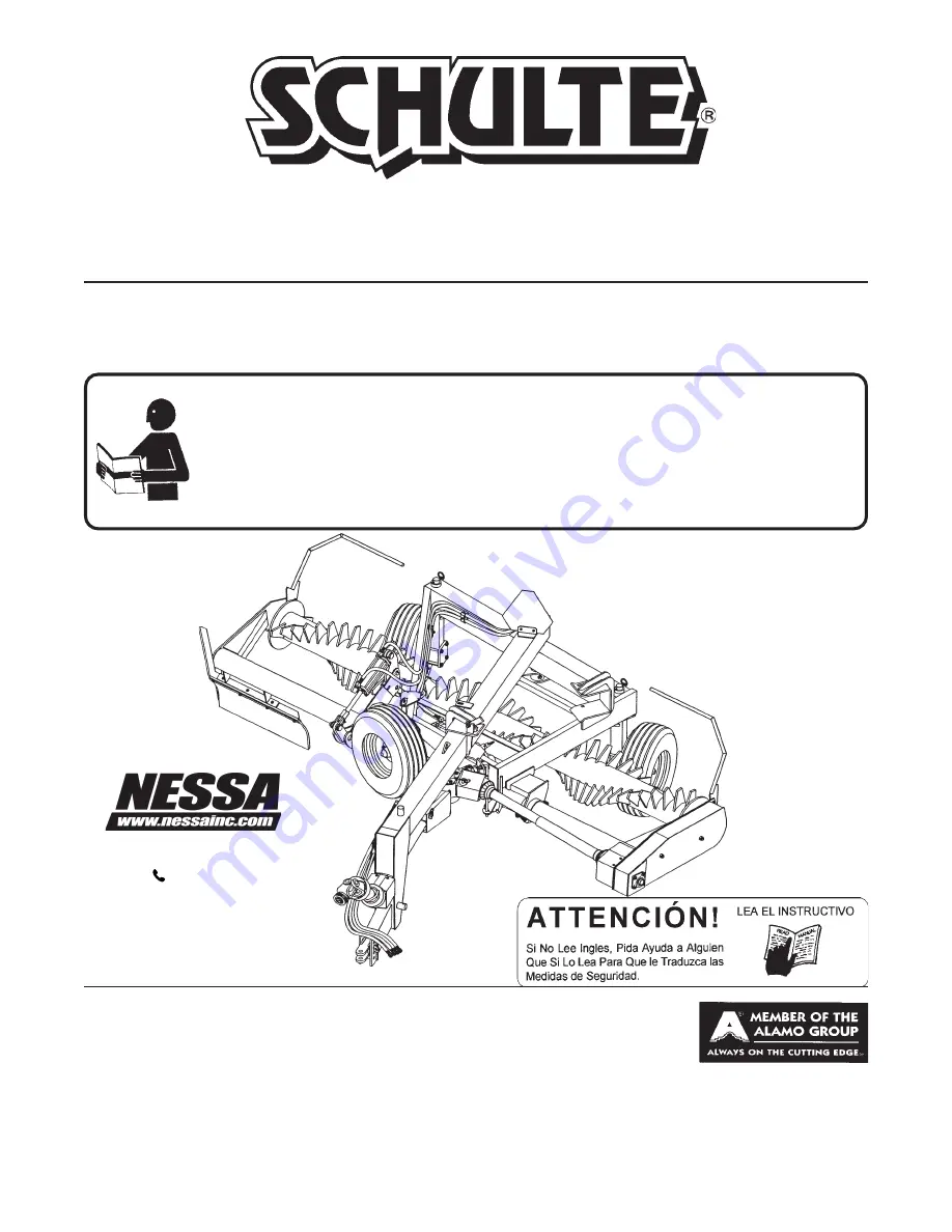
SRW1400
Pivoting Rock Windrower
OPERATOR'S MANUAL
This Operator's Manual is an integral part of the safe operation
of this machine and must be maintained with the unit at all
times. READ, UNDERSTAND, and FOLLOW the Safety and
Operation Instructions contained in this manual before
operating the equipment.
$0.00
73747 130TH ST
ZEARING IA 50276
641-487-7608
WWW.NESSAINC.COM
Summary of Contents for Schulte SRW 1400
Page 5: ...SAFETY SECTION Safety Section 1 1 2003 Alamo Group Inc...
Page 16: ...Safety Section 1 12 SRW1400 10 04 SAFETY 2004 Alamo Group Inc SAFETY 35 37 38 36...
Page 24: ......
Page 25: ...Introduction Section 2 1 INTRODUCTION SECTION...
Page 28: ......
Page 29: ...2003 Alamo Group Inc ASSEMBLY SECTION...
Page 35: ...OPERATION SECTION 2003 Alamo Group Inc Operation Section 4 1...
Page 70: ......
Page 71: ...2003 Alamo Group Inc MAINTENANCE SECTION...
Page 80: ......


