Aerotech AMG100LP, Hardware Manual
The Aerotech AMG100LP Hardware Manual is available for free download from our website. This comprehensive manual provides detailed instructions on using and maintaining your Aerotech AMG100LP. Download your copy today to ensure you get the most out of your product.
Share
Download


Reviews:
No comments
Related manuals for AMG100LP

C-21
Brand: ECO Sensors Pages: 2

iSimple
Brand: AAMP of America Pages: 6

Ergopower Record 12s
Brand: CAMPAGNOLO Pages: 124

ErgoBrain
Brand: CAMPAGNOLO Pages: 100

V2 SUPERCHARGER
Brand: Tesla Pages: 9

4532
Brand: Varec Pages: 70

56H820
Brand: Graphite Pages: 44

T8020
Brand: eufy Security Pages: 12

Drive Pro EZ Build 41130
Brand: Meyer Pages: 11

W-151
Brand: White Outdoor Pages: 4

Radfire RAS Series
Brand: Puretec Pages: 8

70275
Brand: MAXWORKS Pages: 7

SPCOM00000033
Brand: N-Com Pages: 2

SmarTach
Brand: Actia Pages: 102

TX141TH-BV4
Brand: La Crosse Technology Pages: 2

AERASGARD RFTF-C02
Brand: S+S Regeltechnik Pages: 16
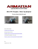
Mini FPV
Brand: Armattan Pages: 11

447575
Brand: Baja Designs Pages: 5


