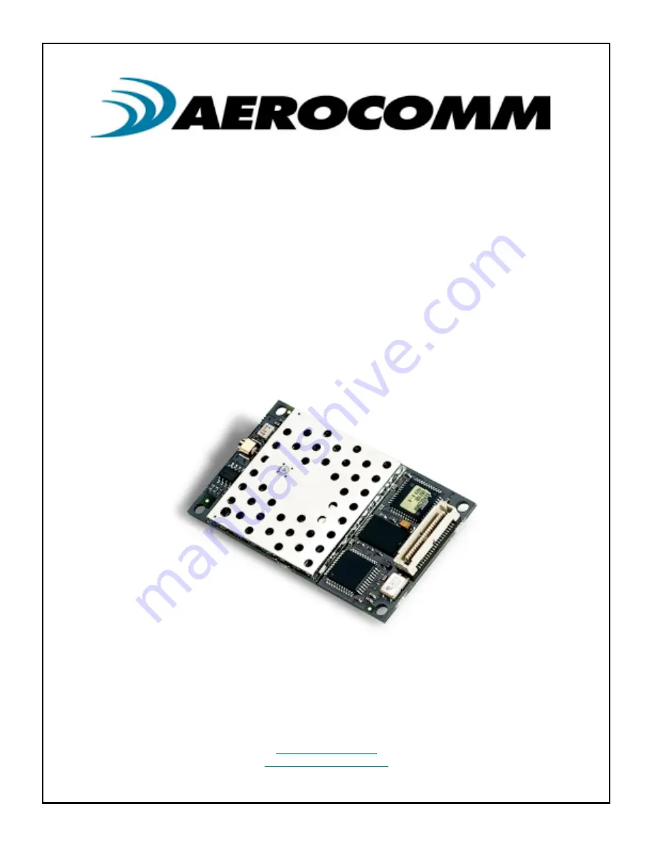
background image

AC5124

AC5124

AC5124

AC5124

2.4 GHz OEM TRANSCEIVER

2.4 GHz OEM TRANSCEIVER

2.4 GHz OEM TRANSCEIVER

2.4 GHz OEM TRANSCEIVER

Specifications Subject to Change

Specifications Subject to Change

Specifications Subject to Change

Specifications Subject to Change

User’s Manual

User’s Manual

User’s Manual

User’s Manual

Version 4.4

Version 4.4

Version 4.4

Version 4.4

10981 EICHER DRIVE

10981 EICHER DRIVE

10981 EICHER DRIVE

10981 EICHER DRIVE

LENEXA, KS  66219

LENEXA, KS  66219

LENEXA, KS  66219

LENEXA, KS  66219

(800) 492-2320

(800) 492-2320

(800) 492-2320

(800) 492-2320

www.aerocomm.com

www.aerocomm.com

www.aerocomm.com

www.aerocomm.com

[email protected]

[email protected]

[email protected]

[email protected]


Summary of Contents for AC5124

Page 1: ...ge User s Manual User s Manual User s Manual User s Manual Version 4 4 Version 4 4 Version 4 4 Version 4 4 10981 EICHER DRIVE 10981 EICHER DRIVE 10981 EICHER DRIVE 10981 EICHER DRIVE LENEXA KS 66219 LENEXA KS 66219 LENEXA KS 66219 LENEXA KS 66219 800 492 2320 800 492 2320 800 492 2320 800 492 2320 www aerocomm com www aerocomm com www aerocomm com www aerocomm com wireless aerocomm com wireless ae...

Page 2: ...s publication are registered trademarks or trademarks of their respective holders This material is preliminary This material is preliminary This material is preliminary This material is preliminary Information furnished by AEROCOMM in this specification is believed to be accurate Devices sold by AEROCOMM are covered by the warranty and patent indemnification provisions appearing in its Terms of Sa...

Page 3: ... 6 Changed description for Diagnostic Result command in Section 6 1 3 Version 4 2 10 25 01 Changed PKLR2400S part number to AC5124C Added AC5124C 200 information Added Section 3 3 Electrical Specifications Added RSSI calibration steps in Section 3 2 1 Added Section 4 6 Addressed Broadcast Communication Added Section 4 7 Handshaking Updated Table 6 EEPROM Parameters to include new parameters Update...

Page 4: ... IC CAN IC CAN IC CAN IC EUR EN EUR EN EUR EN EUR EN AC5124 10 KQL PKLR2400 CAN2268391158A X AC5124 200 KQL PKLR2400 200 CAN2268391180A FCC Notice FCC Notice FCC Notice FCC Notice Antenna Warning Antenna Warning Antenna Warning Antenna Warning WARNING WARNING WARNING WARNING This device complies with Part 15 of the FCC Rules Operation is subject to the following two conditions 1 This device may no...

Page 5: ...00 AC5124 200 AC5124 200A AC5124 200A AC5124 200A AC5124 200A 1 WCP 2400 MMCX Centurion 2 PM M 2 WCR 2400 SMRP Centurion 2 PM 3 MFB24008RPN Maxrad 8 PM 4 BMMG24000MSMARP12 Maxrad 1 PM 5 BMMG24005MSMARP12 Maxrad 5 PM 6 MP24013TMSMARP12 Maxrad 13 M 7 MUF24005M174MSMARP12 Maxrad 5 PM 8 MC2400 Maxrad 2 5 M 9 NZH2400 MMCX External AeroComm 1 PM M 10 NZH2400 I Integrated AeroComm 1 PM M 11 S131CL 5 RMM ...

Page 6: ...cy Identifier Numbers section WARNING WARNING WARNING WARNING This equipment has been approved for portable applications where the equipment can be used in direct contact with the human body Excessive RF exposure should be avoided The preceding statement must be included as a CAUTION statement in manuals for products operating with Antennas 3 4 5 6 7 14 and 15 in the previous table to alert users ...

Page 7: ...AL INTERFACE MODE 03 API 18 4 4 SERIAL INTERFACE MODE 04 TRANSPARENT FIXED PACKET LENGTH NO TIMEOUT 18 4 5 SERIAL INTERFACE BUFFER 18 4 6 ADDRESSED BROADCAST COMMUNICATION 18 4 6 1 Addressed Mode 19 4 6 2 Broadcast Mode 20 4 7 HANDSHAKING 20 4 7 1 CTS Handshaking 20 4 7 2 RTS Handshaking 21 4 7 3 Modem Handshaking 21 5 API COMMAND SET 22 5 1 SYSTEM COMMAND SET 23 5 1 1 Reset 23 5 1 2 Control 24 5 ...

Page 8: ... 14 Transmit Mode 47 7 1 15 RF Mode 1 47 7 1 16 Read Switches 48 7 1 17 Interface Timeout 50 7 1 18 Broadcast Attempts 50 7 1 19 RF Mode 50 7 1 20 Destination IEEE MAC Address 52 7 1 21 Sleep Time 52 7 1 22 Wait Time 52 8 INITIALIZING THE AC5124 TRANSCEIVER 53 8 1 TRANSPARENT MODE INITIALIZATION 53 8 2 API MODE INITIALIZATION 53 9 MECHANICAL OVERVIEW 55 10 ORDERING INFORMATION 57 10 1 PRODUCT PART...

Page 9: ...11 24 03 9 Table 5 Transceiver Command Set 27 Table 6 EEPROM Parameters 37 Table 7 BH BL Selections For Common Baud Rates 43 ...

Page 10: ...user configurable parameter storage AC5124 transceivers operate in a Point to Point or Point to Multipoint Client Server architecture One transceiver is configured as a Server and the others are configured as Clients Data can be transmitted from Client to Server or Server to Client but not from Client to Client or Server to Server The AC5124 runs a proprietary Carrier Sense Multiple Access CSMA pr...

Page 11: ...pical 20mA typical Channels Supports 77 non interfering channels Security User assigned System ID Unique IEEE addresses on each transceiver TRANSCEIVER TRANSCEIVER TRANSCEIVER TRANSCEIVER Frequency Band 2 402 2 478 GHz Transceiver Type Frequency Hopping Spread Spectrum Output Power AC5124 10 AC5124 200 10mW 200mW Input Voltage 5V nominal 2 50mV ripple Sensitivity 90dBm RF Data Rate 882 Kbps Range ...

Page 12: ...he Client transceiver Host Host Host Host Host refers to both the Server Host and the Client Host Server Transceiver Server Transceiver Server Transceiver Server Transceiver The Server transceiver is the Master transceiver It is the hub of all communications Client Transceiver Client Transceiver Client Transceiver Client Transceiver The Client transceiver is a Slave transceiver It is controlled by...

Page 13: ...to communicate to modem 18 NC NC No Connect 19 O RI_OUT Ring Indicator to communicate to computer 20 GND GND Ground 21 GND GND Ground 22 I DCD_IN Data Carrier Detect to communicate to modem 23 O CTS Clear to Send Logic Low Active Low when the transceiver is ready to accept data for transmission See Section 4 7 1 CTS Handshaking Section 4 7 1 CTS Handshaking Section 4 7 1 CTS Handshaking Section 4 ...

Page 14: ...imum value with no other signal present 3 Power up a transceiver that is the opposite type of the one measured in Step 2 i e if the transceiver was a Client power up a Server otherwise power up a Client Make sure the two transceivers are in close proximity and measure RSSI to obtain a maximum value at full signal strength Figure 1 shows approximate RSSI performance There are two versions of receiv...

Page 15: ...e corrupted If Pin 26 is logic high or not connected the baud rate will default to that specified in EEPROM If Pin 26 is logic low at RESET the baud rate will default to 9600 baud 3 2 4 3 2 4 3 2 4 3 2 4 Microprocessor Reset µP_RESET Microprocessor Reset µP_RESET Microprocessor Reset µP_RESET Microprocessor Reset µP_RESET Microprocessor Reset µP_RESET is achieved by holding Pin 38 at logic high fo...

Page 16: ... 0 2Vcc 0 1 V 16 I RXD 0 2Vcc 0 9 Vcc 0 5 0 5 0 2Vcc 0 1 V 17 I RI_IN 2 Vcc 1 0 5 0 8 V 22 I DCD_IN 2 Vcc 1 0 5 0 8 V 26 I BDSEL 0 2Vcc 0 9 Vcc 0 5 0 5 0 2Vcc 0 1 V 27 I RTS 0 2Vcc 0 9 Vcc 0 5 0 5 0 2Vcc 0 1 V 34 I DTR 2 Vcc 1 0 5 0 8 V 37 I WR_ENA 0 7Vcc Vcc 1 0 3 0 5 V 38 I µP_RESET 0 7Vcc Vcc 0 5 0 5 0 2Vcc 0 1 V Table Table Table Table 3 3 3 3 DC Output Voltage Characteristics DC Output Voltag...

Page 17: ...face Timeout expires or until the Fixed Packet Length size is reached Therefore if multiple packets and or portions of packets are sent before the Interface Timeout expires the receiving transceiver Host must be able to process the multiple packets and or portions of packets Packets will be transmitted over the RF interface when one of the following conditions occurs 1 The number of data bytes rec...

Page 18: ... indefinitely until the Fixed Packet Length size is reached Therefore multiple packets and or portions of packets will be sent depending on the timing and size of the packets As a result the receiving transceiver Host must be able to process the multiple packets and or portions of packets 4 5 4 5 4 5 4 5 S S S SERIAL ERIAL ERIAL ERIAL I I I INTERFACE NTERFACE NTERFACE NTERFACE B B B BUFFER UFFER U...

Page 19: ...gnore the remaining attempts and start sending the next packet 4 6 1 2 4 6 1 2 4 6 1 2 4 6 1 2 Auto Destination Auto Destination Auto Destination Auto Destination The AC5124 also supports an addressed mode of communication called Auto Destination Auto Destination is only for Clients operating in one of the Transparent Modes To configure a Client for Auto Destination set bit 7 of EEPROM address 4Fh...

Page 20: ...the IEEE Destination Address set to a value of FFh Unlike the Transmit Attempts process in Addressed Mode a packet will be transmitted until all Broadcast Attempts are completed after which a successful Send Data Complete Send Data Complete Send Data Complete Send Data Complete command will be sent to the Host The number of Broadcast Attempts is specified at EEPROM address 4Eh and can be programme...

Page 21: ...alue of 1 Bit 6 will enable all modem lines except RTS As mentioned in Section 4 7 2 RTS Handshaking Section 4 7 2 RTS Handshaking Section 4 7 2 RTS Handshaking Section 4 7 2 RTS Handshaking setting bit 3 to a value of 1 enables RTS Modem Mode is overkill for most applications and is intended mainly for wireless modem applications 4 7 3 1 4 7 3 1 4 7 3 1 4 7 3 1 Radio Connected to DTE Radio Connec...

Page 22: ...5 Transceiver Command Set 5 Transceiver Command Set Length Length Length Length 2 Bytes This is the total size of the remaining data for this command The length field is in little endian format i e low byte high byte This length does not include the checksum Data Data Data Data N Bytes The actual data associated with the command or sub command Checksum Checksum Checksum Checksum 1 Byte The checksu...

Page 23: ...ired As Required Standby 88h 01h 00h 00h Client Sleep Walk 01h Server Deep Sleep 04h Cancel Standby As Required Status Request 8Ah 01h 00h 0 Reset error counter 1 Don t do anything 8Ah Status Reply 8Bh 14h 74h 00h See Section 5 1 6 Status Section 5 1 6 Status Section 5 1 6 Status Section 5 1 6 Status Reply Reply Reply Reply As Required Update EEPROM Checksum 8Ch 00h 00h No Data 8Ch Check EEPROM Ch...

Page 24: ...Bytes specify starting address Second 2 Bytes specify ending address Remaining bytes specify data to be written Range 00h to 7Fh Data Frame 86h Length Low 00h Sub command Data Checksum Read EEPROM Example Addresses 04h to 09h 86 05 00 02 04 00 09 00 8C Diagnostic Result 87 07 00 02 FF FF FF FF FF FF 82 Example NOP 86 01 00 08 8F Diagnostic Result 87 02 00 08 00 8D Write EEPROM Example write value ...

Page 25: ... Reply Status Reply Status Reply Status Reply A transceiver issues this command to the Host in response to a Status Request Status Request Status Request Status Request command The parameters pertain to the RF Data Link Layer and provide cumulative totals The statistics and their sizes are shown below Name Name Name Name Type Type Type Type Description Description Description Description Size Size...

Page 26: ...issues this command to a transceiver to recalculate the checksum The Host typically issues this command after it has completed writing data to the EEPROM The Host must wait for the Acknowledge Acknowledge Acknowledge Acknowledge command before issuing any additional commands Example 8C 00 00 8C There are no Data bytes for this command Acknowledge 8C 00 00 8C 5 1 8 5 1 8 5 1 8 5 1 8 Check EEPROM Ch...

Page 27: ...Low Low Length Length Length Length High High High High Data Data Data Data Checksum Checksum Checksum Checksum RF Enable 80h 00h 00h No Data 80h Send Data 81h 0Ch 7FBh includes 802 3 Header As Required As Required Send Data Complete 82h 01h 00h 00h or 01h See Section 5 2 3 Send Section 5 2 3 Send Section 5 2 3 Send Section 5 2 3 Send Data Complete Data Complete Data Complete Data Complete As Requ...

Page 28: ...Data MS Byte LS Byte MS Byte LS Byte Note The Data must include the following header information 6 Bytes for the IEEE 802 3 destination address or FF FF FF FF FF FF for broadcast packets 6 Bytes for the IEEE 802 3 source address These unique IEEE addresses are provided by AeroComm and stored in EEPROM addresses 28h 2Dh 5 2 3 5 2 3 5 2 3 5 2 3 Send Data Complete Send Data Complete Send Data Complet...

Page 29: ...sues this command upon detecting a Server beacon after a Reset or after an Out of Range Out of Range Out of Range Out of Range command has been issued to the Host The Client Host will get updated with this command at the time intervals specified by the Range Refresh parameter at EEPROM address 32h The OEM should allow for some hysterisis so the Host isn t flooded with these commands in a fringe co...

Page 30: ...e radio will power back up into normal mode All AT command characters should be capitalized All AT commands end in a 0DH character 13 decimal The radio will not respond to an AT command unless the 0DH character is detected at the end of the command 6 1 6 1 6 1 6 1 IRAM D IRAM D IRAM D IRAM DEFINED EFINED EFINED EFINED IRAM is an acronym for Internal Random Access Memory IRAM is a static memory tha...

Page 31: ...ing the Enter Command Mode command the radio will not be able to communicate with other radios until AT command mode is exited If a server is commanded into AT mode the clients will go out of range 6 2 2 6 2 2 6 2 2 6 2 2 Exit Command Mode Exit Command Mode Exit Command Mode Exit Command Mode To exit AT mode without resetting the internal static parameters of the radio an Exit Command Mode command...

Page 32: ... Where is equal to 0DH 13 decimal Upon successfully receiving the Power on Reset Command the radio will perform a power on reset and resume RF communications 6 2 4 6 2 4 6 2 4 6 2 4 Read IRAM Byte Read IRAM Byte Read IRAM Byte Read IRAM Byte IRAM Reads are performed one byte at a time To read a byte of IRAM the OEM Host should issue the following command to the radio ATSXX Where XX is equal to an ...

Page 33: ...ess than 10H the leading zero must still be sent such as ATS05 YY Where YY is equal to the value to store in the IRAM location If the value is less than 10H the leading zero must still be sent such as ATSFE 0F Where is equal to 0DH 13 decimal If it successfully receives the command the radio will issue the following response to the OEM Host OK Where is equal to 0DH 13 decimal If it is at least abl...

Page 34: ...ual to an EEPROM address If the address is less than 10H the leading zero must still be sent such as ATW05 Where is equal to 0DH 13 decimal If it successfully receives the command the radio will issue the following response to the OEM Host YY Where YY is equal to the value of the EEPROM location requested Where is equal to 0DH 13 decimal If it is at least able to receive the character but there is...

Page 35: ...al to an EEPROM address If the address is less than 10H the leading zero must still be sent such as ATW05 YY Where YY is equal to the value to store in the EEPROM location If the value is less than 10H the leading zero must still be sent such as ATWFE 0F Where is equal to 0DH 13 decimal If it successfully receives the command the radio will issue the following response to the OEM Host OK Where is ...

Page 36: ...r to malfunction may cause a transceiver to malfunction may cause a transceiver to malfunction 2 EEPROM parameters can only be changed when the API Mode is active When operating in a Transparent Mode holding Pin 2 PKTMODE logic low will force a transceiver to enter a pseudo API Mode however the full API command set is not supported Supported commands include Reset Reset Reset Reset Control Control...

Page 37: ...sh 32h 1 20h This byte specifies the number of 200ms ticks between range indications Suggested range is 6 4s to 10s Byte range 20h 32h Server Client Mode 33h 1 02h Server 01h Client 02h System ID 34h 8 00 00 00 00 00 00 00 01 Used to demarcate RF networks Byte range 00h FFh End Character 3Eh 1 FFh This byte specifies the character that will be used to signify the end of a packet Byte range 00h FFh...

Page 38: ...t Mode 0 Radio only transmits 8 bit data 1 Radio transmits 9 bit data Bit 6 Modem Mode 0 Radio does not use modem handshaking 1 Radio uses modem handshaking must set bit 3 also Bit 7 Sleep Walk Mode clients only 0 Radio will not sleep walk 1 Radio will be in sleep walk mode Transmit Mode 4Bh 1 00h 00h Addressed Mode 01h Broadcast Mode RF Mode 1 4Ch 1 00h Bit 0 Reserved Always 0 Bit 1 Read Switches...

Page 39: ...t Pin 28 Bit 7 Auto Destination 0 Client uses programmed Destination IEEE MAC Address 1 Client automatically finds a destination Server on the same Channel and System ID Destination IEEE MAC Address 50h 6 FF FF FF FF FF FF Used in Address Mode Byte range 00h FFh Sleep Time 7Ah 3 00 00 0A Byte range 00h FFh 200ms increments Wait Time 7Dh 3 00 00 20 Byte range 00h FFh 200ms increments 7 1 1 7 1 1 7 ...

Page 40: ...ceiver operating in API Mode will reply with a Send Data Complete Send Data Complete Send Data Complete Send Data Complete command with a Failure Code 1 when the maximum transmits has been attempted without success Transceivers operating in any of the Transparent Modes will not send an acknowledgement to their Host 7 1 5 7 1 5 7 1 5 7 1 5 Receive Mode Receive Mode Receive Mode Receive Mode EEPROM ...

Page 41: ...e Refresh parameter allows the OEM to select the interval of time the Client uses when searching for a Server beacon If a Client is out of range it will search for a Server beacon the amount of time specified by this parameter before reporting an out of range condition A Client reports an out of range condition by taking Pin 15 IN_RANGE logic high and if in API Mode issuing an Out of Range Out of ...

Page 42: ...06 07 08 Network B Channel 4Ah System ID 11 22 33 44 55 66 77 88 Multiple Servers in the same coverage area must be programmed with different Channels to prevent inoperability of the networks The System ID will not prevent inoperability that occurs from locating multiple Servers with the same Channel in the same coverage area 7 1 9 7 1 9 7 1 9 7 1 9 End Character End Character End Character End Ch...

Page 43: ...ing a 28 224 MHz Crystal Using a 28 224 MHz Crystal Using a 28 224 MHz Crystal Baud Rate Baud Rate Baud Rate Baud Rate BH BH BH BH BL BL BL BL Interface Timeout Interface Timeout Interface Timeout Interface Timeout 300 F4h 84h 4Ch 1 200 FDh 21h 14h 2 400 FEh 91h Bh 4 800 FFh 48h 6 9 600 FFh A4h 3 14 400 FFh C3h 3 19 200 FFh D2h 3 28 800 FFh E1h 2 38 400 FFh E9h 2 57 600 default FFh F1h 2 115 200 W...

Page 44: ... is only used by a transceiver operating with Turbo Mode disabled See Section Section Section Section 6 1 18 1 Turbo Mode 6 1 18 1 Turbo Mode 6 1 18 1 Turbo Mode 6 1 18 1 Turbo Mode for details 7 1 13 7 1 13 7 1 13 7 1 13 Serial Interface Mode Serial Interface Mode Serial Interface Mode Serial Interface Mode EEPROM Address 4Ah Length 1 Byte Default 01h There are four Serial Interface Modes for the...

Page 45: ... the same setting for Parity Mode network must have the same setting for Parity Mode 7 1 13 3 7 1 13 3 7 1 13 3 7 1 13 3 Modem Mode Modem Mode Modem Mode Modem Mode EEPROM Address 4Ah bit 6 Length 1 Bit Default 0 Range 0 or 1 Setting this bit to a value of 1 will enable all of the modem lines DCD DSR DTR RI and CTS except RTS Therefore bit 3 must also be set to a value of 1 to enable RTS Otherwise...

Page 46: ...asleep for the duration of Sleep Time unless it receives a byte over the serial interface If this occurs a Client will wake and send the data once it synchronizes with a Server If a Client does not receive a Server beacon it will remain awake until a beacon is received Once synchronized a Client will remain awake for the duration of Wait Time for any additional communications with a Server If a Cl...

Page 47: ...a RF Enable RF Enable RF Enable RF Enable command is issued 88 01 00 01 88 This will command the Server into Deep Sleep Mode 88 01 00 04 8D This will cancel the power down functions 7 1 14 7 1 14 7 1 14 7 1 14 Transmit Mode Transmit Mode Transmit Mode Transmit Mode EEPROM Address 4Bh Length 1 Byte Default 00h Range 00h or 01h This parameter is only valid for transceivers operating in any Transpare...

Page 48: ...are used to force a transceiver to a particular Channel between 0 and 63 When Server Client Pin 15 is logic low a transceiver is forced to become a Server When it is disconnected or forced logic high a transceiver is forced to become a Client 7 1 16 1 7 1 16 1 7 1 16 1 7 1 16 1 End Type End Type End Type End Type EEPROM Address 4Ch bit 2 Length 1 Bit Default 0 Range 0 or 1 This parameter is only v...

Page 49: ...s In situations like this it is useful to set the Limit RF Buffer bit to a value of 1 thus eliminating seven of the eight RF buffers This will allow the Host protocol to control data transfers and hence improve overall throughput 7 1 16 3 7 1 16 3 7 1 16 3 7 1 16 3 RF Priority RF Priority RF Priority RF Priority EEPROM Address 4Ch bit 5 Length 1 Bit Default 0 Range 0 or 1 Setting this bit to a val...

Page 50: ...y the Interface Timeout in this example will range between 27 9ms and 28 8ms Therefore it is important to note that Interface Timeout should be set to be equal to or greater than two byte times at the programmed interface baud rate 7 1 18 7 1 18 7 1 18 7 1 18 Broadcast Attempts Broadcast Attempts Broadcast Attempts Broadcast Attempts EEPROM Address 4Eh Length 1 Byte Default 04h Range 01h FFh The p...

Page 51: ...t is acknowledged 7 1 19 2 7 1 19 2 7 1 19 2 7 1 19 2 Baud Rate Double Baud Rate Double Baud Rate Double Baud Rate Double EEPROM Address 4Fh bit 4 Length 1 bit Default 0 Range 0 or 1 Setting this bit to a value of 1 will double the baud rate programmed in the Baud High and Baud Low bytes at EEPROM addresses 40h and 41h respectively See Section 6 1 10 Baud High BH and Section 6 1 10 Baud High BH an...

Page 52: ...OM address 4Bh 00h enabled When this address is programmed to an actual transceiver address RF layer acknowledgements will be used to guarantee packet delivery If the address is left programmed to the default value all packets sent will be considered broadcast packets without RF layer acknowledgements If Auto Destination is enabled RF layer acknowledgements will be used See Section 4 6 Addressed B...

Page 53: ...ATION NITIALIZATION After the hardware initialization has completed a transceiver operating in API Mode is ready to send and receive API commands as outlined in Section 5 API Command Set Section 5 API Command Set Section 5 API Command Set Section 5 API Command Set At this point the only command that cannot be issued is the Send Data Send Data Send Data Send Data command This command can only be is...

Page 54: ...tion API Mode Initialization API Mode Initialization Apply Power Wait for CTS logic low Host issues RF Enable RF Enable RF Enable RF Enable command Client issues In Range In Range In Range In Range command to Host with Server address Server can now transmit or receive data Client can now transmit or receive data Host reads EEPROM for IEEE source address Host awaits Acknowledge Acknowledge Acknowle...

Page 55: ...erview The AC5124 measures 1 65 W x 2 65 L Critical parameters are as follows J1 J1 J1 J1 40 pin OEM interface connector AMP P N 177986 1 mates with AMP P N 177985 1 MMCX Jack MMCX Jack MMCX Jack MMCX Jack Antenna connector Telegartner P N J01341C0081 mates with any manufacturer s MMCX plug Figure Figure Figure Figure 3 3 3 3 AC5124 with MMCX AC5124 with MMCX AC5124 with MMCX AC5124 with MMCX ...

Page 56: ... 10 Specifications AC5124 10 Specifications AC5124 10 Specifications 11 24 03 56 Figure Figure Figure Figure 4 4 4 4 AC5124 with Integral Antenna AC5124 with Integral Antenna AC5124 with Integral Antenna AC5124 with Integral Antenna ...

Page 57: ...882 Kbps MMCX antenna connector AC5124 200A AC5124 200A AC5124 200A AC5124 200A AC5124 with 200mW output power interface data rates to 882 Kbps integral AeroComm NZH microstrip dipole antenna 10 2 10 2 10 2 10 2 D D D DEVELOPER EVELOPER EVELOPER EVELOPER K K K KIT IT IT IT P P P PART ART ART ART N N N NUMBERS UMBERS UMBERS UMBERS SDK 5124C 10 SDK 5124C 10 SDK 5124C 10 SDK 5124C 10 Includes 2 AC512...

Reviews: