ADLY MOTO ATV-300, Service Manual
The ADLY MOTO ATV-300 is a powerful all-terrain vehicle designed for outdoor adventures. For maintenance and repair, be sure to download the free Service Manual from manualshive.com. This comprehensive manual will provide step-by-step instructions for keeping your ATV in top condition. Get your manual today!
Share
Download


Reviews:
No comments
Related manuals for ATV-300

Grizzly
Brand: Yamaha Pages: 176

GK260
Brand: Lenoxx Pages: 16

PF-200
Brand: Blaw-Knox Pages: 118

T1H1
Brand: AC Air Technology Pages: 46
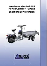
Carrier
Brand: Norsjö Pages: 32

BJ 2021 Series
Brand: BAIC Pages: 254

MIC 84
Brand: Kärcher Pages: 228

AU125
Brand: KAYO MOTOR Pages: 91

PZ50RTX
Brand: Yamaha Pages: 92

YFZ 50 2017
Brand: Yamaha Pages: 132

Magnum 500 2000
Brand: Polaris Pages: 5

R-12-03-01
Brand: Polaris Pages: 13

600 IQ Widetrak
Brand: Polaris Pages: 140

2008 Scrambler 500 2X4 International
Brand: Polaris Pages: 124

Supersport 2007
Brand: Polaris Pages: 266

TS-TRAILER-XT
Brand: Tuff stuff Pages: 17

SLF 2250
Brand: Rosenbauer Pages: 113

H6287
Brand: Grizzly Pages: 12


