Adam 821x, Manual
The Adam 821x manual is a comprehensive guide for users to fully understand and utilize all features of this product. Available for free download from manualshive.com, this manual provides detailed instructions and troubleshooting tips to ensure a seamless user experience. Get your copy today for optimal performance.
Share
Download


Reviews:
No comments
Related manuals for 821x

SOURCE
Brand: JBL Pages: 47

Robot Multifunction NL571
Brand: newcook Pages: 38

SC-HB42F02
Brand: Scarlett Pages: 24

LC9600Z
Brand: Sunbeam Pages: 18

KW-4605
Brand: KYOWA Pages: 3

AirAura X1
Brand: Wheatstone Corporation Pages: 143

MZ5002R
Brand: Home electric Pages: 17

AstroFinder 506
Brand: Meade Pages: 1

04131
Brand: cecotec Pages: 39

49450
Brand: cecotec Pages: 54

VEGATOR 632
Brand: Vega Pages: 60

XDL
Brand: Barco Pages: 88
HC21K
Brand: Black & Decker Pages: 2
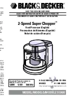
SC400
Brand: Black & Decker Pages: 7

HANDY SHORTCUT II HMP60 Series
Brand: Black & Decker Pages: 3

Ergo EHC650B
Brand: Black & Decker Pages: 2
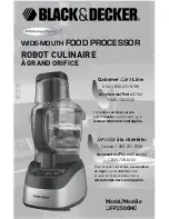
FP2500MC
Brand: Black & Decker Pages: 19

9 IN 1 ULTIMATE VEGETABLE CHOPPER
Brand: Fullstar Pages: 12


