The above diagram is valid only
for clock-and-data type readers.
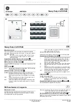
ACT1050 Pin and Proximity
Reader (Entry)
ACT1030 Proximity
Reader (Exit)
Wire both readers in parallel but leave
the SENSE line on the Exit reader unconnected.
Controller
Sense
Clock
Data
+5v
0v
Red Led
Grn Led
C
ard
/P
ro
x R
ea
de
r
2
3
1
5
6
4
8
9
7
0
White
Green
Blue
Red
Black
Brown
Yellow
Orange
Sense
Clock / Data1
Data / Data 0
+5v
0v
Red Led
Grn Led
(Buzzer Ctrl)
Wiring for Clock and Data / Wiegand Reader
The +5V reader supply on ACT controllers is normally rated
at 100mA. Typically this is sufficient to power 2 ACT readers.
Note however that readers from other manufacturers may need
to be powered separately if their current requirements exceed
this or if they require 12V.
The standard wiring colours for
ACTPro Proximity and Pin readers
is shown above. Readers
should be a maximum of 30m
from the controller when powered
from +5V and a maximum of 100m
when powered from +12V.
OM
RO
N
5A
2
50
VA
C
5A
3
0V
DC
OM
RO
N
1A
12
5V
AC
1A
30
VD
C
5-12V dc
0V
0 1 2 3 4 5 6 7 8 9
B A T C H:
P R ODUC T :
S E R IA L NUMB ER :
02X X -1
AC T P ro R E V 1.3
00X X X X
Data / D0
C lock / D1
Sense
R ed L E D
Grn L E D
B uzz C trl
Internal buzzer is
activated by applying
0V to Buzz Ctrl
Rear view of ACTPro 1040/1050/1060
connected to the ACT2000/1000/DS100
For Wiegand readers .
Wire both readers in parallel but connect D0
line of the exit reader into the SENSE line on
the controller,leave the SENSE line on the
Exit reader unconnected.
Unit 8 Tallaght Business Centre, W hitestown, Tallaght, Dublin 24, Ireland.
Telephone: 353 1 462 2585. Telefax: 353 1 462 2587. E-mail: sales@ accesscontrol.ie W eb: www.accesscontrol.ie
Wiring for Entry/Exit Readers
ACTPro Product Range
1030/1040/1050/1060
Downloaded from: http://www.guardianalarms.net