Accu ESS R050100, User Manual
The Accu ESS R050100 user manual is essential for operating this remarkable product with ease. Download the comprehensive manual free of charge from our website to fully unlock the potential of your Accu ESS R050100 device.
Share
Download


Reviews:
No comments
Related manuals for ESS R050100

Premier
Brand: ABSCO SHEDS Pages: 21

CI 3000
Brand: ECKELMANN Pages: 134
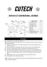
80100-CT
Brand: Cutech Pages: 2

5BIG NAS PRO
Brand: LaCie Pages: 22

BLACKOUT WINDOW STORAGE SYSTEM
Brand: REBEL OFF ROAD Pages: 9

REPLACE TAPE DRIVE IN STORAGELOADER VXA...
Brand: Tandberg Data Pages: 10

Expansion 750GB
Brand: Seagate Pages: 1

GD-MS013
Brand: Argus Pages: 24

PG-HDH61A
Brand: Fujitsu Pages: 12

PG-HD6G1C
Brand: Fujitsu Pages: 16

MPG3xxxAT
Brand: Fujitsu Pages: 201

PG-HD2E4H
Brand: Fujitsu Pages: 14

MPC3045AH
Brand: Fujitsu Pages: 185

MPC3032AT
Brand: Fujitsu Pages: 179

MPA3017AT
Brand: Fujitsu Pages: 176

MPD3091AH
Brand: Fujitsu Pages: 191

MJA2080BH
Brand: Fujitsu Pages: 320

MPD3043AT
Brand: Fujitsu Pages: 191


