Acard ADR-7008L, User Manual
Discover the comprehensive User Manual for the Acard ADR-7008L to maximize your device's capabilities. This essential guide is available for free download, ensuring you can effortlessly master your product's features. Access the manual now exclusively at manualshive.com. Don't miss out on detailed, user-friendly instructions!
Share
Download


Reviews:
No comments
Related manuals for ADR-7008L

Pro Series
Brand: easynet Pages: 30

DC511P Operator's
Brand: Pace Pages: 22

ARK-2250S
Brand: Advantech Pages: 80

STR-0484
Brand: Smartec Pages: 7

AH Series
Brand: Digiop Pages: 85
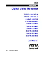
CADVR-1004-WD
Brand: Honeywell Pages: 63

H.264 HRDP
Brand: Honeywell Pages: 106
EVOLUTION 2
Brand: Honeywell Pages: 2

Fusion IV
Brand: Honeywell Pages: 150

FUSION III DVR
Brand: Honeywell Pages: 168

FUSION
Brand: Honeywell Pages: 168

HD-DVR-1004
Brand: Honeywell Pages: 182

HD-16DVR-C
Brand: Honeywell Pages: 169
HDVR
Brand: Honeywell Pages: 238

CADVR-04D
Brand: Honeywell Pages: 240

HRDV 16 Duplex
Brand: Honeywell Pages: 2

OVR 2000
Brand: Omnivision Pages: 82

ICR-B170NX
Brand: Sanyo Pages: 4


