background image

Introduction


Hardware Setup


BIOS Setup 

Driver & Utility CD 

Appendix 


SG-95


Motherboard 
Socket 775 
 

Intel Pentium D / Pentium 4 / 

Celeron / Celeron D / Core 2 Duo 


User’s Manual


LGA775 mATX Motherboard


SiS 662/SiS 966L 


800MHz FSB


DDR2 667/533 


Integrated SiS Mirage 1 
Graphics GPU 


2x SATA 1.5Gb/s RAID 0/1 


7.1 HD Audio 

Summary of Contents for SG-95

Page 1: ...ty CD Appendix SG 95 Motherboard Socket 775 Intel Pentium D Pentium 4 Celeron Celeron D Core 2 Duo User s Manual LGA775 mATX Motherboard SiS 662 SiS 966L 800MHz FSB DDR2 667 533 Integrated SiS Mirage 1 Graphics GPU 2x SATA 1 5Gb s RAID 0 1 7 1 HD Audio ...

Page 2: ...t indirect special incidental or consequential damages arising from any defect or error in this manual or product Product names appearing in this manual are for identification purpose only and trademarks and product names or brand names appearing in this document are the property of their respective owners This document contains materials protected under International Copyright Laws All rights res...

Page 3: ...s 2 6 2 4 3 FAN Power Connectors 2 7 2 5 Installing Hardware 2 8 2 5 1 CPU Socket 775 2 8 2 5 2 DDR2 Memory Slots 2 11 2 6 Connecting Peripheral Devices 2 12 2 6 1 Floppy and IDE Disk Drive Connectors 2 12 2 6 2 Serial ATA Connectors 2 13 2 6 3 Additional USB 2 0 Port Headers 2 14 2 6 4 Internal Audio Connectors 2 15 2 6 5 Front Panel Audio Connection Header 2 15 2 6 6 PCI and PCI Express X16 X1 S...

Page 4: ...5 Appendix 5 1 5 1 Troubleshooting How to Get Technical Support 5 1 5 1 1 Q A 5 1 5 1 2 Technical Support Form 5 4 5 1 3 Universal ABIT Contact Information 5 5 iv SG 95 ...

Page 5: ...L Memory 2x 240 pin DIMM slots support maximum memory capacity up to 2GB Supports Single Channel 64bit mode DDR2 667 533 Un buffered Non ECC memory Graphics Integrated SIS Mirage 1 Graphics GPU high performance 256 bit 3D engine and 2D Accelerator LAN Onboard 10 100Mb LAN Serial ATA Supports 2 ports SATA 1 5Gb s RAID 0 1 JBOD Audio Onboard 7 1 CH HD Audio Expansion Slots 1x PCI Express X16 slot 1x...

Page 6: ...io Connector Surround Left Surround Right Rear Left Rear Right Center Subwoofer Mic In Line In Line Out 1x RJ 45 LAN port 4x USB 2 0 ports RoHS Compliancy 100 Lead free process and RoHS compliancy Miscellaneous Micro ATX form factor 224mm x 245mm Specifications and information contained herein are subject to change without notice 1 2 SG 95 ...

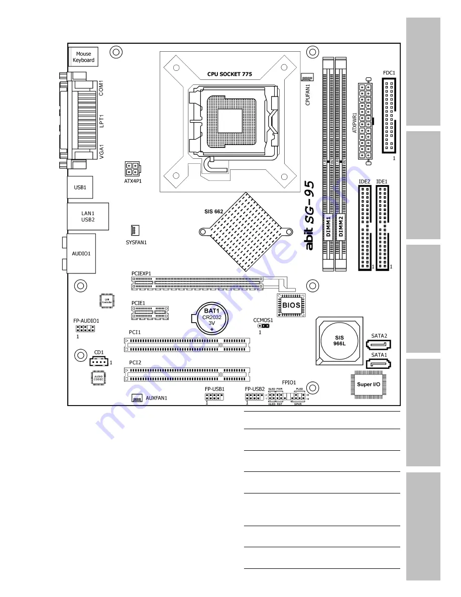
Page 7: ...Introduction 1 2 Motherboard Layout SG 95 1 3 ...

Page 8: ...1 4 SG 95 ...

Page 9: ... for I O shield located at the rear panel Make sure the I O shield of the chassis matches the I O port configuration of this motherboard You can find an I O shield specifically designed for this motherboard in its package 2 2 Installing Motherboard Most computer chassis have a base with many mounting holes to allow the motherboard to be securely attached and at the same time protected the system f...

Page 10: ...ve them tightened Face the chassis s rear panel To prevent shorting the PCB circuit please REMOVE the metal studs or spacers if they are already fastened on the chassis base and are without mounting holes on the motherboard to align with 2 3 Checking Jumper Settings For a 2 pin jumper plug the jumper cap on both pins will make it CLOSE SHORT Remove the jumper cap or plug it on either pin reserved ...

Page 11: ...ave it reconfigured to the default values stored in BIOS Pins 2 and 3 shorted default Normal operation Pins 1 and 2 shorted Clear CMOS memory To clear the CMOS memory and load in the default values 1 Power off the system and disconnect with AC power source 2 Set pin 1 and pin 2 shorted by the jumper cap Wait for a few seconds Set the jumper cap back to its default settings pin 2 and pin 3 shorted ...

Page 12: ...the backup battery 1 Power off the system and disconnect with AC power source 2 Remove the exhausted battery 3 Insert a new CR2032 or equivalent battery Pay attention to its polarity The side is its positive polarity 4 Connect AC power source and power on the system 5 Enter the BIOS setup menu Reconfigure the setup parameters if necessary CAUTION Danger of explosion may arise if the battery is inc...

Page 13: ...e connectors ATX 24 Pin Power Connector The power supply with 20 pin or 24 pin cables can both be connected to this 24 pin connector Connect from pin 1 for either type However a 20 pin power supply may cause the system unstable or even unbootable for the sake of insufficient electricity A minimum power of 300W or higher is recommended ATX 12V 4 Pin Power Connector This connector supplies power to ...

Page 14: ...on will only cause the LED not lighting but a wrong connection of the switches could cause system malfunction HLED Pin 1 3 Connects to the HDD LED cable of chassis front panel RST Pin 5 7 Connects to the Reset Switch cable of chassis front panel SPKR Pin 13 15 17 19 Connects to the System Speaker cable of chassis SLED Pin 2 4 Connects to the Suspend LED cable if there is one of chassis front panel...

Page 15: ...onnectors each provide power to the cooling fans installed in your system CPUFAN1 CPU Fan Power Connector SYSFAN1 System Fan Power Connector AUXFAN1 Auxiliary Fan Power Connector These fan connectors are not jumpers DO NOT place jumper caps on these connectors ...

Page 16: ...is not in use 2 5 1 CPU Socket 775 1 Place the board so as to let the lever hook of the socket is on your left side Use your left thumb and forefinger to hold the lever hook pull it away from the retention tab Rotate the lever to fully open position 2 Use your right thumb on the bottom right side of the load plate and lift it up to fully open position 3 Use your right thumb and forefinger to grasp...

Page 17: ...t hand to hold the load plate and use your right thumb to peel the cap off The cap plays an important role in protecting contact pins In order to prevent bent pin PUT ON the cap after operation or testing 6 Lower the plate onto the CPU package Engage the load lever while gently pressing down the load plate 7 Secure the lever with the hook under retention tab ...

Page 18: ...r plug from the heatsink and fan assembly to the CPU FAN connector The installation procedures vary with different types of CPU fan and heatsink assembly The one shown here is served for demo only For detailed information on how to install the one you bought refer to its installation guidelines A higher fan speed will be helpful for better airflow and heat dissipation Nevertheless stay alert to to...

Page 19: ...y press the module into the slots until the ejector tabs at both sides of the slot automatically snap into the mounting notch Do not force the DIMM module in with extra force as the DIMM module only fits in one direction 6 To remove the DIMM modules push the two ejector tabs on the slot outward simultaneously and then pull out the DIMM module Static electricity can damage the electronic components...

Page 20: ...on both the FDC1 port and the floppy connector Each of the IDE port connects up to two IDE drives at Ultra ATA 100 mode by one 40 pin 80 conductor and 3 connector Ultra ATA 66 ribbon cables Connect the single end blue connector at the longer length of ribbon cable to the IDE port of this board the other two ends gray and black connector at the shorter length of the ribbon cable to the connectors o...

Page 21: ...t SATA device 1 Attach either end of the signal cable to the SATA connector on motherboard Attach the other end to SATA device 2 Attach the SATA power cable to the SATA device and connect the other end from the power supply The motherboard in this illustration is served for DEMO only may not be the same type or model as the one described in this user s manual ...

Page 22: ...ports by connecting bracket or cable to the rear I O panel or the front mounted USB ports of your chassis Pin Pin Assignment Pin Pin Assignment 1 VCC 2 VCC 3 Data0 4 Data1 5 Data0 6 Data1 7 Ground 8 Ground 10 NC Make sure the connecting cable bears the same pin assignment 2 14 SG 95 ...

Page 23: ... you must carefully check the pin assignment before connecting from the front panel module An incorrect connection may cause malfunction or even damage the motherboard Please do not connect the Ground cable or USB VCC cable from the front panel module to the Pin 4 AVCC of this header Pin Pin Assignment HD AUDIO Pin Pin Assignment AC 97 AUDIO 1 MIC2 L 1 MIC In 2 AGND 2 GND 3 MIC2 R 3 MIC Power 4 AV...

Page 24: ...nally configured to support HD Audio For AC 97 audio connection you may 1 Right click the Realtek HD Audio Manager icon in system tray 2 Click Audio I O tab and then click Connector Settings 3 Click Disabled front panel jack detection and then click OK to confirm 2 16 SG 95 ...

Page 25: ...ware Setup SG 95 2 17 2 6 6 PCI and PCI Express X16 X1 Slots Install PCI Express X16 graphics card into slot PCIEXP1 Install PCI Express X1 card into slot PCIE1 Install PCI cards into slots PCI1 and or PCI2 ...

Page 26: ...tc LAN1 Connects to Local Area Network AUDIO1 S L S R Surround Left Surround Right Connects to the surround left and surround right channel in the 7 1 channel audio system Cen Sub Center Subwoofer Connects to the center and subwoofer channel in the 7 1 channel audio system R L R R Rear Left Rear Right Connects to the rear left and rear right channel in the 7 1 channel audio system Line In Connects...

Page 27: ...powering it off and then back on After pressing Del key the main menu screen appears Main Setup This menu displays the system overview of BIOS version processor type memory size and configures the system date and time options BIOS SETUP UTILITY Main Advanced PCIPnP Boot Security Chipset Power Exit Use ENTER TAB or SHIFT TAB to select a field Use or to configure system Date System Overview AMIBIOS ...

Page 28: ...ht 1985 2005 American Megatrends Inc PCIPnP Setup This menu configures the options for IRQ settings latency timers etc BIOS SETUP UTILITY Main Advanced PCIPnP Boot Security Chipset Power Exit Value in units of PCI clocks for PCI device latency timer register Advanced PCI PnP Settings WARNING Setting wrong values in below sections may cause system to malfunction PCI Latency Timer 64 Allocate IRQ to...

Page 29: ...F1 General Help F10 Save and Exit ESC Exit v02 59 C Copyright 1985 2005 American Megatrends Inc Security Setup This menu configures the BIOS protecting options BIOS SETUP UTILITY Main Advanced PCIPnP Boot Security Chipset Power Exit Install or Change the password Security Settings Supervisor Password Not Installed User Password Not Installed Set Password Change User Password Boot Sector Virus Prot...

Page 30: ...p This menu configures the power management BIOS SETUP UTILITY Main Advanced PCIPnP Boot Security Chipset Power Exit Go into On Off Standby or Suspend when Power button is pressed APM Configuraion Power Button Disabled Suspend Time Out Disabled Power On Ring Disabled Wake Up by LAN Disabled Wake Up by PME of PCI Disabled Keyboard WakeUp Disabled Mouse WakeUp Disabled Wake Up by Alarm Disabled Rest...

Page 31: ...et Power Exit Exit system setup after saving the changes F10 key can be used for this operation Save Changes and Exit Discard Changes and Exit Discard Changes Load Optimal Defaults Load Failsafe Defaults Select Screen Select Item Enter Go to Sub Screen F1 General Help F10 Save and Exit ESC Exit v02 59 C Copyright 1985 2005 American Megatrends Inc ...

Page 32: ...3 6 SG 95 ...

Page 33: ...he CD ROM drive in your system The following installation auto run screen appears If not browse the root directory of the CD ROM via the File Manager and double click the AUTORUN file Drivers Click to enter the driver installation menu Manual Click to enter the user s manual menu Utility Click to enter the utilities installation menu Browse CD Click to browse the contents of this Driver Utility CD...

Page 34: ... Click on the Drivers tab in the installation menu screen 2 Click the SiS VGA Driver item The installation screen appears 3 Follow the prompts on the screen to complete installation 4 Restart the system for the driver to take effect Install this chipset driver first after having installed operating system 4 2 SG 95 ...

Page 35: ...or the onboard 7 1 CH HD Audio To install this driver 1 Click on the Drivers tab in the installation menu screen 2 Click the Realtek HD Audio Driver item The following screen appears 3 Follow the prompts on the screen to complete installation 4 Restart the system for the driver to take effect ...

Page 36: ... in the installation menu screen 2 Click the SiS LAN Driver item The installation screen appears 3 Follow the prompts on the screen to complete installation 4 Restart the system for the driver to take effect 4 4 USB 2 0 Driver There is no need to install this driver for Windows 2000 with Service Pack 4 Windows XP with Service Pack 1 or their later version 4 4 SG 95 ...

Page 37: ...Start install operating system 3 Insert this driver disk into floppy disk drive when the screen instruction prompts you to install a third party SCSI or RAID driver 4 Press F6 key and then follow the screen instruction to complete the installation To create a driver disk 1 Click on the Utility tab in the installation menu screen 2 Click the Generate SiS Raid Floppy Disk The following screen appear...

Page 38: ...t BIOS file from our Website Save the BIOS file to this bootable disk 3 Copy the AMI Flash Utility amiflash exe from the Driver Utility CD through the path CD ROM Drive UTILITY AMIFLASH and save it to the same bootable disk 4 Reboot the system in DOS mode by using the same bootable disk 5 At the prompt type AMIFLASH bios rom P N C X then press Enter The bios rom is the ROM file name Do not turn of...

Page 39: ... to over clocking or non standard status We suggest the following three troubleshooting methods to discharge CMOS data recover the hardware default status and then making the motherboard work again There is no need to bother returning the motherboard to where you bought it from or go through an RMA process Step 1 Switch off the power supply unit and then switch it on again after one minute If ther...

Page 40: ...previously installed in the system Re install and start the system one at a time until the system won t start Malfunction in the OS If the system hangs after resuming from S3 or some testing program if the CPU cannot be recognized properly if the display resolution mixed or if a certain program cannot be executed etc you may Upgrade the motherboard s latest BIOS version Upgrade the add on device s...

Page 41: ...ondMax 10 SATA 300GB on SATA 3 Example 2 Maxtor DiamondMax 10 SATA 300GB 2 on SATA 3 SATA 4 RAID 1 Optical devices Type in the brand and specifications of your optical drives and quantity Specify if it was inserted on IDE Master or Slave or SATA ports Other devices Indicate which add on cards or USB devices that you absolutely sure are related to the problem If you cannot identify the problem s or...

Page 42: ... name Last Name Subject Motherboard BIOS Version CPU Memory brand Memory size Memory configuration Graphics card Graphics driver version Power supply maker Power supply wattage Storage devices Optical devices Other devices Operating system Problem description ...

Page 43: ...l Greece Denmark Norway Sweden Finland Switzerland Universal ABIT NL B V Jan van Riebeeckweg 15 5928LG Venlo The Netherlands Tel 31 77 3204428 Fax 31 77 3204420 Austria Czech Romania Bulgaria Slovakia Croatia Bosnia Serbia Macedonia Slovenia Universal ABIT Austria Computer GmbH Schmalbachstrasse 5 A 2201 Gerasdorf Wien Austria Tel 43 1 7346709 Fax 43 1 7346713 Contact office abit austria at Websit...

Page 44: ...P N 4310 0000 36 Rev 1 00 http www abit com tw ...

Reviews: