RELION
®
REB500
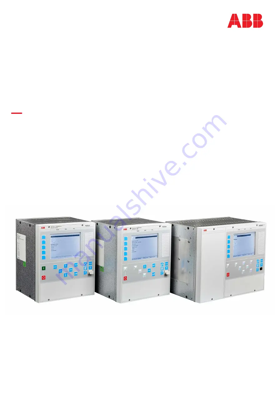
Bay protection functions REB500
Version 8.3 IEC
Technical manual
/t1ainm1:nu
Events
Measurements
Disturbance records
Settings
2013-03-3010:5
3:.10
j$superUser
joi,jectname
a
/Mainmenu
=
I
;
D
D
i!9?
J
;;:::
e
t
�,�
SettirlgS
confi�ation
rua,gr,ostics
rests
O•�
L¥19"39f�
-
I D I
; =
D
=