ABB REG650 ANSI, Product Manual
The ABB REG650 ANSI Commissioning Manual is a comprehensive resource for users looking to set up and optimize their REG650 ANSI protection relay. This detailed manual covers all aspects of installation, configuration, and commissioning, providing step-by-step instructions. Download this invaluable manual for free from our website.
Share
Download


Reviews:
No comments
Related manuals for REG650 ANSI

W3000 - SA Subwoofer - 200 Watt
Brand: Sony Pages: 2
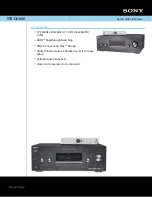
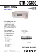
STR-DG800
Brand: Sony Pages: 2
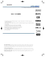
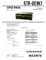
STR-DE997 - Fm Stereo/fm-am Receiver
Brand: Sony Pages: 2

SS-V831ED
Brand: Sony Pages: 2

SAW2500 - SA Subwoofer
Brand: Sony Pages: 1

SS-V831ED
Brand: Sony Pages: 5
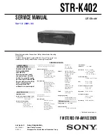
STR-K402 - Fm Stereo/fm-am Receiver
Brand: Sony Pages: 36

STR-K700 - Fm Stereo/fm-am Receiver
Brand: Sony Pages: 46

STR-K402 - Fm Stereo/fm-am Receiver
Brand: Sony Pages: 51
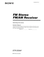
STR-DE997 - Fm Stereo/fm-am Receiver
Brand: Sony Pages: 71
STR-DE997 - Fm Stereo/fm-am Receiver
Brand: Sony Pages: 78
STR-DG800
Brand: Sony Pages: 92
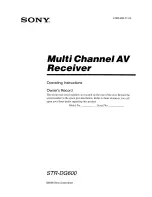
STR-DG600 - Multi Channel Av Receiver
Brand: Sony Pages: 95
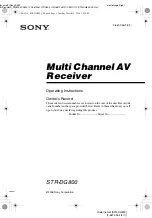
STR-DG800
Brand: Sony Pages: 100

STR-DG2100 - Multi Channel A/v Receiver
Brand: Sony Pages: 134

WEGA KLV-20SR3
Brand: Sony Pages: 162

ER-1015
Brand: Toa Pages: 2

GM-19340
Brand: Body Armor 4x4 Pages: 7


