background image


— 

A BB MEA SU RE ME NT  & ANA L YT ICS | O PE RATI N G  I NS T RUCT IO N  |  OI/ GAC4 00- EN   RE V. A 
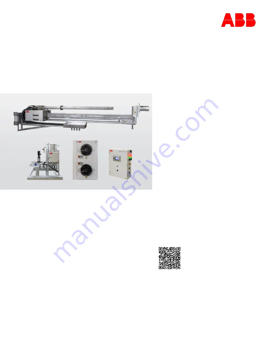
ProKiln GAC400 

Probe gas sampling system 


— 
ABB Measurement & Analytics 

 
For your local ABB contact, visit: 

www.abb.com/contacts 
 

For more product information, visit: 

www.abb.com/analytical 


Sampling system for dry gas 
sampling at rotary cement kiln gas 
exit and calciner gas exit. 

Measurement made easy 


O

I/

G

A

C4

0

0

-EN

 R

ev

. A


0

9.

20

23

 O

rig

in

al

 In

st

ru

ct

io


— 
ProKiln GAC400 

Introduction 

The ProKiln sampling system is especially 
designed for analysis in hot cement flue gases 
with high content of dust and aggressive gas 
components. The system is made by cement 
specialists for use in the rough environment of a 
cement plant. 
 
The ProKiln sampling system is preferably 
combined with ABB’s AO2000 System. However, 
the ProKiln sampling system is built to be self-
supporting which allows it to easily be connected 
and retrofitted to any existing well-functioning 
gas analysis system or other third-part suppliers 
solution. 
 
The system controller interface offers a large 
variety of industry leading communication 
options together with conventional terminal 
based digital and analogue status signals. 


Additional Information 

Additional documentation on ProKiln GAC400 is 
available for download free of charge at 
www.abb.com/analytical. 
Alternatively simply scan this code: 


— 


We reserve the right to make technical changes or modify the contents of this 
document without prior notice. With regard to purchase orders, the agreed particulars 
shall prevail.  
ABB does not accept any responsibility whatsoever for potential errors or possible lack 
of information in this document.  
 
We reserve all rights in this document and in the subject matter and illustrations 
contained therein. Any reproduction, disclosure to third parties or utilization of its 
contents – in whole or in parts – is forbidden without prior written consent of ABB. 
 
© ABB 2023 

3KXG174400R4201 


Summary of Contents for ProKiln GAC400

Page 1: ...vironment of a cement plant The ProKiln sampling system is preferably combined with ABB s AO2000 System However the ProKiln sampling system is built to be self supporting which allows it to easily be...

Page 2: ...ample gas line to the retractor 50 7 Electrical connections 51 Safety instructions 51 Connecting internal electric cables 51 Connecting external electric cables 54 8 Commissioning 56 Safety instructio...

Page 3: ...rmation in this document can lead to a risk of damage to property injuries or even death In order to ensure safety all personnel handling the probe gas sampling system must have read and understood th...

Page 4: ...e product may only be performed if expressly permitted by these instructions Information and symbols on the product must be observed These may not be removed and must be fully legible at all times The...

Page 5: ...les These rules are intended for all persons handling the probe gas sampling system in any situation Purpose of these rules The purpose of these rules is to ensure that all persons handling the probe...

Page 6: ...cumstances If cooling water tubes or compressed air tubes burst shut down the probe gas sampling system and secure it against being switched on again If errors are detected shut down the system and se...

Page 7: ...the retractor or probe Do not enter the danger area around the retractor until it is at standstill and the warning lamps and buzzer are off Never stand in the danger area around the retractor when th...

Page 8: ...spiratory protection against toxic gases Keep the time in which the duct opening is open as short as possible Hot cooling water During operation of the probe gas sampling system the cooling water in t...

Page 9: ...ressed air tubes with no additional connector Associated warning sign in this operating instruction WARNING Pressurized system dangers Risk of injury in the area of the probe gas sampling system due t...

Page 10: ...on The protective installations must not be disabled and must be checked for proper functioning at regular intervals The illustration below shows the location of the protective installations on the pr...

Page 11: ...ck ensures that the duct opening is reliably closed when working near the duct opening Protective fence installation with electric lock access Location Protective fence installation with electric lock...

Page 12: ...echanical expert Electrical maintenance personnel On mechanical parts Maintenance Troubleshooting Maintenance Shutting down Electrical expert With experience with controllers Storage personnel Correct...

Page 13: ...rams etc to protect the product the network its system and the interface against any kind of security breaches unauthorized access interference intrusion leakage and or theft of data or information AB...

Page 14: ...r conditioning of the analysis gas takes place in external equipment not part of the probe sampling system The following figure shows a general overview of the ProKiln GAC400 probe gas sampling system...

Page 15: ...sampling system will run the sequence of gas sampling and probe cleaning based on set intervals 10 The probe gas sampling system will run the sequence of moving the probe in and out of the process bas...

Page 16: ...Dr in F a 1 a6 a5 V5 1 ptional o V5 2 tional op Pos 1 Pos 0 V5 3 tional op P t urge Ven V6 Included comp air connect o p ints i n o a1 1 alv pipe connect on F g i a2 1 hose stu connection b a3 1 hose...

Page 17: ...rature measurement Is part of monitoring the process heat input to the probe Protects the probe against overheating Is used as base temperature for process heat input T12 Probe cooling water flow out...

Page 18: ...explained in the Description of the controller section 2 Emergency reset Reset of Emergency Stop after it has been released Indication that Emergency Stop is pushed Blue constant Indication that Emer...

Page 19: ...downstream Heating function prevents condensation from building up 7 Heated connection box for external heated hose Connection point for heated hose leading to external gas analysis system Heating fun...

Page 20: ...robe is in manual operation 4 Safety breaker Safety breaker for probe motor When off the main power to the motor is off and the probe is not able to move Flange Shutter To protect people and equipment...

Page 21: ...Connects the periphery filter cleaning nozzle to one air blaster for powerful cleaning of filter sample area 6 Water cooling forward Connects the probe to the cooling panel 7 Water cooling return Con...

Page 22: ...probe are removed by regularly moving the probe in and out using the retractor Cleaning the probe intake hole by means of centre tube nozzle connected to air blaster Incrustations on the intake hole...

Page 23: ...parameters Water pump operation Water tank temperature Water tank water levels Cooling water flow rate Figure 8 Water panel Pos Component Function 1 Water pump Re circulate the cooling water 2 Tempera...

Page 24: ...the actual flow which has been cooling the probe Monitoring is performed on the HMI on the control cabinet Requirements for the water supply The water supply must meet the following minimum requiremen...

Page 25: ...the tip of the probe The compressed air system also serves to operate the optional flange shutter Requirements The compressed air must meet the following minimum requirements Category Requirement Dew...

Page 26: ...access the control system operators will use the Human Machine Interface HMI located on the front of the control cabinet If the ProKiln GAC400 is connected to an ABB AO2000 System gas analysis system...

Page 27: ...ervice mode Alarm status lights and sound tower Figure 14 Alarm status lights and sound tower Indication Function Meaning Green Flashing light Retractor is locked in safe position Green Constant light...

Page 28: ...nd pressure release if available 2 Pressure alarm Alarm for low compressed air pressure 3 Ball valve Compressed air supply User interfaces Operation screen The figure below shows a typical operation s...

Page 29: ...es Access permissions Setup for system optimization limits etc Edit tolerance ranges Network settings PID Setpoints Critical setpoints of alarms etc Important information about passwords Level 2 and 3...

Page 30: ...for hysteresis control of water cooler fan 75 C 167 F Stop Stop temperature for hysteresis control of water cooler fan 70 C 158 F Flow See Parameter input Alarm setpoint menu on page 33 for alarm limi...

Page 31: ...line length on site 30 sec V5 2 sample gas valve optional Open heated sample shut off valve to allow process gas to flow to gas analysis system downstream if available Not configurable Cleaning menu...

Page 32: ...move 60 sec Parameter input PID H1 Probe heater Setup menu Figure 26 PID H1 Probe heater Setup menu Parameter input Function Default value Setp Temperature set point of sample tube inside of the prob...

Page 33: ...ance request 150 C T03 TAH Heated shut off valve temperature high maintenance request 190 C T03 TAL Heated shut off valve temperature low maintenance request 150 C T10 TAHH Water tank temperature high...

Page 34: ...ower supply electrical connections 7 CE mark 8 Warning triangle acc to EN 61010 observe instructions 9 European Union WEEE sign do not throw in trash Figure 30 Nameplate example Note Products that are...

Page 35: ...rminals and main switch frequency converter wiring Warns about hot surfaces A risk of hot surfaces can be expected during operation Particular danger areas are all cooling water tubes water panel cool...

Page 36: ...y appropriately trained personnel may transport the transport units and only with the aid of the recommended transport equipment Do not stand under suspended loads Follow the transport instructions in...

Page 37: ...e The unpacked retractor must not be transported using a fork lift truck Cooling unit 350 kg Only store after draining all water Lifting gear may only be attached at the designated lifting points 1 se...

Page 38: ...term max 95 occasional slight condensation is permitted Unpacking the system Instructions Perform the following steps to unpack the system 1 Remove outer packaging Transport crate Tensioning straps Ca...

Page 39: ...of the attachments Only store after draining all water out of the internal tubes Environmental conditions Observe the following physical limits with regards to storing the various modules Module Envi...

Page 40: ...ng and respiratory protection against toxic gases Keep the time in which the duct opening is open as short as possible Introduction This section contains a list of tasks to be performed when installin...

Page 41: ...n or dust influx must be present Choosing the place of installation of the control cabinet Position to set up the cooling module defined No direct heat radiation or dust influx must be present Choosin...

Page 42: ...lations 3 Lift probe retractor together with flange shutter and position in front of insertion tube flange of the kiln wall Remove the two mounted transport legs Note Store the transport legs for any...

Page 43: ...a tool in case the probe needs to be removed from the buggy for maintenance activities 1 Retractor buggy lock 2 Probe transportation support Figure 37 Retractor buggy lock and probe transportation su...

Page 44: ...legs Remove after installation Figure 38 How to lift the probe Lifting instructions Use only the included crane shackles for lifting Weight 1200 kg Note Figure 38 is shown without flange shutter to b...

Page 45: ...5 Installation flanges points on the retractor flange shutter 1 Process flange at the flange shutter 3 Matching flange ASME B16 5 Slip on Welding Class 150 2 Installation flanges 4 2 on each side Figu...

Page 46: ...sed 7 ASME B16 5 Slip On Welding Flange Kiln center lineass 150 8 8 Install flange pipe to be welded to kiln foot wall 9 Installation flange pipe 8 0 Min kiln center line height 1200 mm 47 in k Max ki...

Page 47: ...install flange Figure 41 Customer supplied install flange ASME B16 5 Slip On Welding Flange Class 150 8 1 Length of pipe to be determined on site 2 Pipe to be cut flush with inside kiln lining bricks...

Page 48: ...sembly screws or bolts Installing the water system and cooling panel Screws required for assembly 4 4 galvanized steel screws or stainless material M16 or bolts M16 Requirements The following requirem...

Page 49: ...doubt Only use hoses in areas where no heat or mechanical wear occurs 1 hoses between Water panel and Cooling panel are included for install next to each other If distance is larger than the length of...

Page 50: ...d sample gas line through the side of the junction box and fix it with the supplied holder The figure below shows the heated junction box with cover left and without cover right Heated sample gas line...

Page 51: ...the various modules can be found in the electrical connection plan enclosed inside the control cabinet when supplied All required internal lines are pre installed in the probe retractor Cooling panel...

Page 52: ...iew A Power supply and cable connections between units B General power supply C Uninterruptible power supply UPS D Signals from Central Control Room Analysis system to the ProKiln system E System Stat...

Page 53: ...fan motor 230 VAC cable to probe retractor for brake probe 230 VAC cable to the retractor unit heating 24 VDC cable for safety installations 24 VDC cable to the retractor unit ProfiNet bus cable from...

Page 54: ...leads have an adequately dimensioned protective device circuit breaker General voltage requirements 230 400 VAC 10 50 Hz fuses 3 x 20 A required 3 phase connection 5 wires N conductor necessary or 230...

Page 55: ...ce probe retracts out of the and flange shutter closes Protective installation 1 contact closed from device probe works normally Connection option for air cannon In order to prevent dangers caused by...

Page 56: ...ress the EMERGENCY STOP switch immediately if anyone is still in the danger area around the retractor after the warning lamps light up or the warning buzzer buzzes WARNING Pressurized system dangers R...

Page 57: ...ressed air switch in the pneumatic box Checking the pneumatic system on page 62 8 In the control cabinet check frequency drive has no alarm Checking correcting operating parameters on page 64 9 Check...

Page 58: ...n the water tank top cover to a side to allow anti freeze to be filled in tank 4 Release approximately 33 of the water tank capacity 5 Add the 33 of anti freeze to the water tank 6 Close the water tan...

Page 59: ...occurs anywhere and close the covers Activation of the probe gas sampling system Requirements The connected gas analyser system must be switched on Observe the warm up time of the gas analyser system...

Page 60: ...s sampling system on the side of the control cabinet 2 General power supply 3 UPS power supply Figure 48 Control cabinet retractor system electrical cabinet 3 Turn on the power supply for the water sy...

Page 61: ...page 62 Starting frequency converter and adapting control parameters on page 63 Checking correcting operating parameters on page 64 Power breakers in the control cabinet The illustration below shows t...

Page 62: ...Note Wait until the temperature of the cooling water is below 40 C Before starting to work on the system Figure 51 Water system 3 After work is completed check of any leakages before returning the pro...

Page 63: ...he retractor are used to define the various positions needed in order for the probe to enter the kiln in the most favourable way By selecting the Encoder Menu button a window will pop up with a warnin...

Page 64: ...Proceed as follows 1 Check that the water flow in the water cooling system is correct see Default operation parameter settings on page 30 The rotor of the water pump must run according to arrow indica...

Page 65: ...te system is ready to sample because the probe is equipped with internal electrical heating of the gas conducting tube 11 Switch the gas sampling probe to automatic mode using the HMI Home page Result...

Page 66: ...bout to move at any moment Press the EMERGENCY STOP switch immediately if anyone is still in the danger area around the retractor after the warning lamps light up or the warning buzzer buzzes WARNING...

Page 67: ...water gets in the eyes despite protective glasses rinse them thoroughly under cold running water holding the eyelids open Contact medical specialist according to local regulations Monitoring automati...

Page 68: ...the analyser if the sample gas condenses in the sample gas tube part of the SO2 dissolves in the condensation which in turn decreases the SO2 concentration measured in the analyser In the above mentio...

Page 69: ...case Calciner gas outlet Because of the greater flow speeds in this process after start up the gas sampling probe must be checked frequently for wear at the calciner gas outlet measuring point If dist...

Page 70: ...off any adhering material then goes back to measuring position S3 The probe never leaves the insertion tube so as to prevent any dust to be blown outside of the process Clean in AUTOMATIC mode remote...

Page 71: ...the probe buggy until the probe has reached its end position and the warning signal goes out Result The gas sampling probe is automatically retracted out of the kiln and enters Manual mode of operatio...

Page 72: ...menu For an overview of access permissions in the various areas of the control system please refer to the section on Access permissions Navigation The user navigates the interface at the bottom of th...

Page 73: ...oling water circuit Air bubbles in the cooling water circuit caused by too high temperature Check the water flow Check if piping has lime deposits limiting the flow Use lime removing liquid in tank se...

Page 74: ...intenance Request yellow or Alarm menus red The illustration above shows the Menu page with error indication at the top right corner in this example there are no active alarms therefore the system is...

Page 75: ...OFF Check water pump switch 150S3 on side of water system control cabinet Emergency Stop Emergency Stop button has been pushed and not released and reset Release Emergency switch and push Emergency re...

Page 76: ...aintenance Request at the top right corner of the HMI plus a green OK indication showing that the system is still operating It can also be seen that the Alarm originates from a 101S2 safety switch as...

Page 77: ...emperature forward temperature sensor error Check cable connection T12 Ai Error Water temperature return temperature sensor error Check cable connection F12 Ai Error Flow sensor error Check cable conn...

Page 78: ...inal box to turn off before performing any corrective action Instructions Proceed as follows to handle any errors 1 Operation Service Mode 50S15 switch must be is in the Service Mode 2 Switch system t...

Page 79: ...probe retractor and air blaster probe blow back 11 Insert gas sampling probe into the kiln Path Main Probe Position Go S3 WARNING Gas sampling probe moves into the kiln Do not stand in the area of tr...

Page 80: ...f the probe gas sampling system no longer works after prolonged storage in adverse conditions after severe transport stress It is recommended to have the probe gas sampling system maintained by the AB...

Page 81: ...m cleaning the system on page 102 X Display and evaluate trend display Evaluating trend displays on page 104 X Functional test of residual current circuit breaker Checking the residual current circuit...

Page 82: ...just the position of the probe Probe retractor Checking and tightening the drive chain on page 117 X X Cooling system Maintenance task See Inspection Maintenance intervals As required Daily Weekly Twi...

Page 83: ...cooling flow 2 Water return Water outlet for cooling flow 1 1 Probe core 1 2 Probe base 1 3 Inspection port centre air blaster connection 1 4 Flange seal adjustable 1 8 Probe tip filter cartridge and...

Page 84: ...Reference Designation 1 Process flow direction 2 Sample connection heated sample tube connected to filter 3 Periphery air blaster 3 x tube connection to filter periphery air blaster 4 Filter blow bac...

Page 85: ...ipe cooling 1 2 16 2 x pt100 sensor for water cooling temperatures 1 2 17 2 x O ring inner tube cooling jacket O ring OD72 ID84 6 Viton 1 2 18 1 x O ring middle tube water separator O ring OD96 ID88 4...

Page 86: ...n and clean out entrance 1 3 1 x O ring for inspection port 1 3 1 Swagelok straight connector 3 4 SS 1210 1 12W BT 1 3 2 Swagelok tee welded 3 4 1 3 3 Dacapo DN20 union DJ10343000 1 3 4 Dacapo DN20 un...

Page 87: ...nozzle for air blaster Equipment Reference Designation 1 8 1 1 8 2 1 8 3 Filter female thread front D46x25 Filter body D46 42x460 Filter female thread back D46x25 1 8 4 Center nozzle for air blaster...

Page 88: ...retractor Equipment Reference Designation 1 Control cabinet retractor control components 2 Pneumatic cabinet valves and pressure switch 2 1 Center beam 2 2 Covers 2 3 Chain support low 2 4 Chain supp...

Page 89: ...B 3 3 Support Probe 3 4 Buggy frame 3 5 Rail attachment 3 6 Wheel plate L_B 3 7 Wheel plate R_B 3 8 Buggy beam 3 9 Chain anker_B 3 10 Wheel protection_B 3 20 V track wheel 3 21 Conical bushing 3 22 Ex...

Page 90: ...4 6 Blaster tank air supply with ball valves valves not shown in drawing 4 20 Accumulator tank 5L 2x 4 21 Lock handle 4 22 blinding plugs 2x 4 30 Filter blow back supply 4 31 Filter blow back 4 32 Fil...

Page 91: ...1 Support Chain 5 2 Cable tray 5 3 Support front 5 4 Base cover 5 5 Connection base with 3 1 unions for compressed air and cooling water 5 7 Heated valve box option connection box to heated sample gas...

Page 92: ...NG SYSTEM OI GAC400 EN REV A 11 Maintenance Equipment layout plan Illustration flange shutter automatic 293 202 300 250 6 1 6 2 6 3 6 4 6 5 6 6 6 7 6 9 6 10 6 14 6 11 6 12 6 8 6 13 6 17 6 20 6 30 6 12...

Page 93: ...44 6 3 Shutter seal 6 4 Flange front cut 6 5 Flange front stear 6 6 Shutter sides 6 7 Shutter stear 6 8 shutter rail L 6 9 shutter rail R 6 10 Shutter connect 6 11 Shutter cyl lid 6 12 Front flange 6...

Page 94: ...94 ProKiln GAC400 PROBE GAS SAMPLING SYSTEM OI GAC400 EN REV A 11 Maintenance Equipment layout plan Illustration water system 3 4 5 2 1...

Page 95: ...Water return 1 union for min 1 connection to probe 3 Water from cooler 1 hose connection to cooler 4 Control cabinet water system 5 Optional water heater 7 1 Lid water tank 7 10 Water pump 7 12 Level...

Page 96: ...ayout plan Illustration cooling system Equipment Reference Designation 8 4 2 x Emergency stop fan motors 8 11 Water to water tank 1 hose connection to water tank 8 12 Water return from water system 8...

Page 97: ...18 Controller CPU 25 Frequency drive for retractor motor 33 HMI panel for control 34 General and UPS power 36 Warning signal tower 37 Emergency stop 46 Connections to probe retractor and cooling panel...

Page 98: ...ve equipment Closed overalls with long trousers and long sleeves Safety shoes preferably boots covering ankles Safety gloves suitable for mechanical work Safety glasses Protective helmet If necessary...

Page 99: ...ch the hot probe wear a face mask against heat heat proof gloves and protective welder s clothing WARNING Harmful gases jet flames Danger due to harmful gases and jet flames in the area of the duct op...

Page 100: ...ee Safety instructions for maintenance work on page 98 Introduction The service switch puts the system into service mode If work described in the following maintenance instructions must be performed i...

Page 101: ...MERGENCY STOP switch and turn the Safety switch 101S2 at the probe rear cabinet to OFF 8 Push Emergency Reset button 15SB 15P12 at the front of the control cabinet to allow movement of the probe 9 Tur...

Page 102: ...clean the duct opening when the rotary kiln is in operation Wear a face mask against heat heat proof gloves and protective welder s clothing and respiratory protection against toxic gases Keep the ti...

Page 103: ...rails in the same way Also the energy chain containing hoses must be cleaned with compressed air 4 Check condition of drive chain with regard to the following chain tension chain link wear Correct Bug...

Page 104: ...ust be stable above 90 l min The water cooling temperature return will change depending on process and if scaling or build up occurs on the probe 3 The Trend Heat Input menu will show how much heat is...

Page 105: ...ystem will not record any process data apart from these Alarm and event log Data can only be transferred to ABB Service if the customer removes the USB stick and sends the files to ABB for service rev...

Page 106: ...shutting down the kiln if possible as the test procedure disables all monitoring mechanisms If it is necessary to check during operation while the kiln is running the probe retractor must be located...

Page 107: ...pling probe moves into the kiln Do not stand in the area of travel of the gas sampling probe or probe buggy until the probe is completely inserted into the kiln and the warning lamps sounds goes out 9...

Page 108: ...uctions for maintenance work on page 98 Introduction Sample gas paths the compressed air system and cooling water circuit must be checked for leaks on a regular basis Maintenance interval twice yearly...

Page 109: ...ed tool Follow instructions Probe Replacing the intake filter on page 115 6 Clean the surfaces inside the probe sample inlet with a brush and a cloth making sure only minimum dust is left 7 Insert inc...

Page 110: ...peration Mode Instructions checking the compressed air system How to check the cooling water circuit for leaks 1 Operation Service Mode 50S15 switch must be in the Service Mode 2 Switch system to manu...

Page 111: ...em to manual mode on the HMI if this has not already been done Path Home Manual 3 Retract gas sampling probe out of the kiln Path Menu Probe Position GO S0 WARNING The probe moves out of the kiln Do n...

Page 112: ...system to Auto mode on the HMI Path Home Auto 12 Operation Service Mode 50S15 switch must be switch back to Operation Mode Probe Removing incrustations Safety measures WARNING Dangers when performing...

Page 113: ...aning 7 Cleaning inspection of center pipe Follow opening instructions for Inspection clean out through center pipe inspection port on page 114 Inspection of the center pipe can only be done while the...

Page 114: ...1 in the back end of the probe 2 Remove cover 1 to access the center pipe inspection port 2 located at the end of the center pipe 3 Remove the flange of the center pipe inspection port 2 by unscrewin...

Page 115: ...onditions must be met The probe is retracted to maintenance position S0 Safety switch probe 101S2 in OFF position to prevent any movement of the probe see Safety instructions for maintenance work on p...

Page 116: ...it is not possible to clean anymore due to excessive clogging or if it looks damaged Part is available through ABB Service 10 Replace the filter sealing 2 with ceramic string 17cm shown below Use tap...

Page 117: ...forming this work Wear a face mask against heat heat proof gloves and protective welder s clothing Operation Service Mode 50S15 switch must be in the Service Mode with a padlock Additionally press the...

Page 118: ...u can pull it vertically approximately 0 5 1 cm by hand on the middle of the retractor unit 7 If the chain is too loose or if you can see wear on the chain support Increase tension with the chain tens...

Page 119: ...should be maximum 30 cm inside the rotary kiln beyond the kiln seal after start up The gas sampling probe must not be inserted further than absolutely necessary into the rotary kiln in order to minimi...

Page 120: ...r flange 2 on the flange shutter 1 Bolt 2 Counter flange Figure 56 Adjusting the probe flange 5 Adjusting the vertical position Release the support bolt 1 red supporting the probe to allow for adjustm...

Page 121: ...the button Override S0 and S3 for manual operation of probe Use the push buttons Probe In 1 and Probe Out 2 on the retractor control cabinet to position the probe at the correct length of 200mm Use a...

Page 122: ...eratures below 5 C add approximately 30 of anti freeze Anti freeze requirements If ambient temperatures below 5 C can be expected you must add anti freeze ABB recommends Glycol as anti freeze Anti fre...

Page 123: ...water pump on the Water Cooling Pump ON OFF switch on the side of the water system control panel Let flow run for a few minutes 16 When completed stop the pump and remove all the liquid by releasing t...

Page 124: ...eze with skin wash off the skin immediately with water and soap Contact medical specialist according to local regulations If cooling water or anti freeze gets in the eyes despite protective glasses ri...

Page 125: ...e with national legislation 2 Remove hoses between water panel and cooler panel 23 Apply low pressure compressed air 1 bar to the heat exchanger top to force out water from the heat exchanger until no...

Page 126: ...ation Preferably install or remove the probe when the rotary kiln is out of operation If you install or remove the probe when the rotary kiln is in operation Wear a face mask against heat heat proof g...

Page 127: ...und they are not designed to support the complete weight of the probe and retractor Further procedure The following table shows further procedure If the system follow the following instructions is to...

Page 128: ...as sampling system Unit HxWxL mm Weight kg Control unit 1000x800x300 75 Probe 400x4500x400 100 Retractor unit 400x4500x400 700 Water panel 1200x800x700 250 Cooling unit 1200x1700x900 300 Sound emissio...

Page 129: ...ocuments Note All documentation declarations of conformity and certificates are available in ABB s download area www abb com analytical Trademarks PROFINET are registered trademarks of PROFIBUS PROFIN...

Page 130: ...Company Address Contact person Telephone Fax Email Device details Type Serial no Reason for the return description of the defect Was this device used in conjunction with substances which pose a threa...

Page 131: ...ProKiln GAC400 PROBE GAS SAMPLING SYSTEM OI GAC400 EN REV A 131 Notes...

Page 132: ...out prior notice With regard to purchase orders the agreed particulars shall prevail ABB does not accept any responsibility whatsoever for potential errors or possible lack of information in this docu...

Reviews: