background image

— 

A B B ME A SUR EMENT & A N A LY TIC S | USER GU IDE
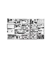
C1300

Advanced circular chart recorder

Measurement made easy

For more information

Further publications are available for free download 
from:

www.abb.com/measurement

or by scanning this code: 

Search for or click on

C1300

Advanced circular chart recorder
Datasheet

DS/C1300-EN

C1300

Advanced circular chart recorder 
User Guide supplement
Advanced sofware options

IM/C1300-ADV

C1300

Advanced circular chart recorder 
User Guide supplement
Modbus communications option

IM/C1300-MOD

C1300 advanced circular 
chart recorder

Summary of Contents for C1300

Page 1: ...rom www abb com measurement or by scanning this code Search for or click on C1300 Advanced circular chart recorder Datasheet DS C1300 EN C1300 Advanced circular chart recorder User Guide supplement Advanced sofware options IM C1300 ADV C1300 Advanced circular chart recorder User Guide supplement Modbus communications option IM C1300 MOD C1300 advanced circular chart recorder ...

Page 2: ...ced in full or part without prior approval of the Technical Publications Department Health and Safety To ensure that our products are safe and without risk to health the following points must be noted The relevant sections of these instructions must be read carefully before proceeding Warning labels on containers and packages must be observed Installation operation maintenance and servicing must o...

Page 3: ... 3 8 Relay Configuration 42 3 9 Digital Input and Output Configuration 43 3 10 Analog Output Configuration 45 3 11 Logic Equation Configuration 47 3 12 Data Logging Configuration 50 3 13 System Clock Configuration 54 3 14 Pen Function 55 3 15 Calibration 56 3 16 Backing Up and Restoring Configurations 58 3 16 1 Backing Up a Configuration 58 3 16 2 Restoring a Configuration 59 4 Mechanical Installa...

Page 4: ...s fitted to the appropriate pen arm Each pen arm is identified by a colored band see Fig 1 1 If the violet true time line event option is fitted the pen records on the same time line as the red pen but on the outer edge of the chart Fig 1 1 Fitting the Pen Capsule s Gently pull the pen arm off its bracket 3 Note Do not bend the pen arm during removal and re fitting as pen clashing may result Raise...

Page 5: ...wn firmly to ensure that the 2 locating pins pierce the paper 6 Ensure pen s in raised position 1 Input 1 999 99 deg C Fit a chart ensuring that it is beneath the pen lifter bars Locate chart under guides Rotate chart to align the time line with the red pen 3 4 Red Pen 5 Lower pen s 7 Input 1 999 99 deg C Switch off the power supply to the recorder 8 ...

Page 6: ...or the pens to settle 2 The start up self test sequence shown in Fig 1 3 is shown on display screen 1 when the power supply is first switched on Fig 1 3 Recorder Start up Self test Sequence WWW abb com Self Tests Software Key and Module Identification Instrument Type and Software Version C1314J Software Issue 1 Main CFG Test Pass SKey Type B Pass Mod2 Not Fitted Mod3 Not Fitted Mod4 Not Fitted Mod...

Page 7: ...Not Fitted Mod5 Dig Out Fail Mod6 RS485 Pass Acknowledge Input 1 999 99 deg C Component Possible Cause Action Module in position 2 Module in position 3 Module in position 4 Module in position 5 Module in position 6 Main Board Software Key Analog input and or analog output calibration is corrupt Power down and then up again If the fault persists contact the Company Configuration stored in non volat...

Page 8: ...Menu Screen Press to open the main menu screen Select Channel Pen 4 3 2 1 Pen 1 Tag Boiler 1 Edit _ Pen 1 Tag _ 01234 56789 ABCDEFGHI JKLMNOPQRSTUVWXYZ _ abcdefghijklmnopqrs tuvwxyz WºdbSp Exit Cursor Use the and keys to select the character to be displayed at the cursor position see Note below Use the key to move the cursor Press to save the new value and advance to the next screen Pen 1 Eng Hi 1...

Page 9: ...or3 F inpt Unspecified error from the Analog to Digital Converter Corrupt data from the Analog to Digital Converter No reply from the Analog to Digital Converter Input is above or below fault detection level or Input exceeds the limits for the linearizer selected Check that the input output board is located correctly in its socket see Section 5 1 Power down and up If the error message is still pre...

Page 10: ...ys are configured separately see Pen Ch Display and Totals Display in Section 3 4 and each can be displayed in one of several ways Input channel information can be displayed without totalizer information and vice versa Input channel 1 and 2 information and system time date is shown on display screen 1 If the recorder is fitted with the optional second faceplate Input channel 3 and 4 information to...

Page 11: ...onds Fast Rate each screen is displayed in turn for 5 seconds Press the key from any Operating Page screen to initiate Autoscroll in Slow Rate mode Press the key again to switch to Fast Rate mode When in Fast Rate mode press the key to switch to Slow Rate mode When in Slow Rate mode press the key to switch Autoscroll off Press the key at any time to switch Autoscroll off Input 1 999 99 deg C Autos...

Page 12: ...ection 3 4 see Sections 2 3 6 to 2 3 10 Optional Data Logging hardware installed see Section 2 3 11 page 15 Optional Data Logging hardware not installed and Totalizer software option enabled by installation of the appropriate software key and Totals Display set to Off Section 3 4 continued below System Time Date Display Notes Available only if any one of the Totalizer Math or Timers software optio...

Page 13: ...he appropriate software key and optional Data Logging hardware not installed return to top of page Totalizer software option enabled by installation of the appropriate software key and Totals Display not set to Off Section 3 4 see Sections 2 3 6 to 2 3 10 Optional Data Logging hardware installed see Section 2 3 11 page 15 Optional Data Logging hardware not installed and Totalizer software option e...

Page 14: ...tion 3 14 only a measured value of 0 is displayed for that channel Totalizer Math or Timers software options not enabled by installation of the appropriate software key and optional Data Logging hardware not installed return to top of page Totalizer software option enabled by installation of the appropriate software key and Totals Display not set to Off Section 3 4 see Sections 2 3 6 to 2 3 10 Opt...

Page 15: ... 3 7 page 35 Totalizer 1 Totalizer tag Totalizer value Totalizer value units Totalizer 2 Optional data logging hardware installed see Section 2 3 11 page 15 Optional data logging hardware not installed see Section 2 3 3 page 10 Totalizer 1 Channel tag Measured value and measured value units Totalizer value Totalizer value units Totalizer 2 Optional data logging hardware installed see Section 2 3 1...

Page 16: ...ction 3 7 page 35 Totalizer 1 Totalizer tag Totalizer value Totalizer units Measured value and measured value units Totalizer 2 Optional data logging hardware installed see Section 2 3 11 page 15 Optional data logging hardware not installed see Section 2 3 3 page 10 Totalizers 1 and 2 Totalizer tag Totalizer value Totalizer units Optional data logging hardware installed see Section 2 3 11 page 15 ...

Page 17: ...ormation on current data logging status Press the key to place data logging off line When data logging is off line the Compact Flash card can be removed safely If the card is not removed within 1 minute data logging is placed on line automatically A timer indicates the number of seconds remaining before data logging resumes This screen is displayed when a Compact Flash card is not inserted Data lo...

Page 18: ... the totalizer number see Section 3 7 page 35 Press the key to open the Main Menu Highlight Totalizer Log Select Totalizer Select the totalizer log to display Totalizer Log The first log displayed for the selected totalizer is the most recent Use the key to display each log in descending date order Date and time Totalizer tag Current value and units Maximum minimum and average values Note If no lo...

Page 19: ...n Menu Highlight Totalizer Control Select Totalizer Select the totalizer to reset Reset Totalizer Select YES to reset the totalizer Confirm Reset Totalizer Select YES to reset the totalizer Note If YES is selected the totalizer is reset when the key is pressed Return to previous frame Select Totalizer Totalizer 1 Totalizer 1 Reset NO 000000913 Operating Level Totalizer Log Totalizer Control Alarm ...

Page 20: ...djust is set to YES see Section 3 4 page 20 Press the key to open the Main Menu Highlight Alarm Adjust Select Alarm Select the alarm to adjust Alarm Set Point Adjust the alarm set point Return to top of page Select Alarm A1 A1 Trip 10 000 deg C Operating Level Totalizer Log Totalizer Control Alarm Setpoints Security Code Common Channels Alarms Select Alarm A1 ...

Page 21: ...from 0 to 9999 see Configure Password in Section 3 4 on pgae 20 When set to anything other than 0 access to all configuration menus i e all menus below Security Code is prevented Enter the correct code to enable access to the configuration menus Note Isolate any external alarm control circuits if inadvertent operation during configuration is undesirable The recorder responds instantly to parameter...

Page 22: ...age 77 for a description of sources Auto Pen Drop Select YES to enable the pen s to drop automatically onto the chart 5 minutes after they are lifted If NO is selected the pen s remain lifted until they are dropped manually by the operator Pen Lift Enable Select YES to enable the pen s to be raised and lowered using the pen lift key Configure Password Select a code between 1 and 9999 Continued on ...

Page 23: ... 3 and 4 pen recorders only is shown separately on display screen 2 see Section 2 3 3 page 10 Dual input channel information for channels 1 and 2 is shown simultaneously on display screen 1 Input channel information for channels 3 and 4 3 and 4 pen recorders only is shown simultaneously on display screen 2 see Section 2 3 4 page 11 Separate Dual input channel information for channels 1 and 2 is fi...

Page 24: ... shown separately on display screen 1 The current measured values for channels 3 and 4 3 and 4 pen recorders only together with totalizer values for totalizers assigned to channels 3 and 4 are shown separately on display screen 2 see Section 2 3 8 page 14 Dual Total totalizer values for totalizers assigned to channels 1 and 2 are shown simultaneously on display screen 1 Totalizer values for totali...

Page 25: ...rast setting for display screen 1 between 0 and 100 Contrast 2 Note Shown only if faceplate 2 is fitted Select the required contrast setting for display screen 2 between 0 and 100 Brightness 1 Select the required brightness setting for display screen 1 between 0 and 100 Brightness 2 Note Shown only if faceplate 2 is fitted Select the required brightness setting for display screen 2 between 0 and 1...

Page 26: ...0 F engineering display range and 10 below 0 F engineering display range in the event of a fault being detected and or the fault detection level being exceeded the process variable is driven upscale Input Type Linearizer Type 5 2 3 2 Ö RTD THC N THC B THC E THC L THC J THC T THC S THC R THC K None Temp Units Engineering Range Display Range Programme Filter F C None RTD THC Current Voltage Millivol...

Page 27: ...ction or Pen X Source where X is the pen number is set to Off or None respectively Section 3 14 that pen cannot be selected Pen X Function set to Trend Section 3 14 continued on next page Pen X Function set to Event Section 3 14 continued on page 30 Select Channel Pen 1 Totalizer Control Alarm Setpoints Security Code Common Channels Alarms Totalizers Relays Pen 1 Tag Input 1 Edit Pen 1 Off Tag Pen...

Page 28: ...hermocouple Thermocouple Rtd Resistance thermometer Return to top of page Linearizer Type Select the required linearizer type None No linearizer Type K Type K thermocouple Type R Type R thermocouple Type S Type S thermocouple Type T Type T thermocouple Type J Type J thermocouple Type E Type E thermocouple Type N Type N thermocouple Type B Type B thermocouple Rtd Resistance thermometer Square Root ...

Page 29: ... maximum electrical input value required within the limits shown in Table 3 1 Electrical Input Range Low Set the minimum electrical input value required within the limits shown in Table 3 1 Decimal Point Select the decimal point position for the engineering and chart ranges Continued on next page Input Type Electrical Range Low Electrical Range High Minimum Span Low to High Millivolts 0 150 5 0 Mi...

Page 30: ...next page Degrees Celsius Degrees Fahrenheit Linearizer Type Minimum Maximum Minimum Span Minimum Maximum Minimum Span Type K 100 1300 65 148 2372 117 Types R S 18 1700 320 0 3092 576 Type T 250 300 60 418 572 108 Type J 100 900 50 148 1652 90 Type E 100 900 45 148 1652 81 Type N 200 1300 90 328 2372 162 Type B 18 1800 710 0 3272 1278 Rtd 200 600 25 328 1112 45 Performance accuracy is not guarante...

Page 31: ... High bar causes an analog input failure fault to be detected below 30 bar and above 270 bar Notes On some ranges the input circuitry may saturate before the fault level setting is reached In this case an error is detected below the level set If an input exceeds the minimum or maximum value for the selected linearizer an error is detected regardless of the fault level setting Pen Filter Filters th...

Page 32: ...creen and save the tag Pen Out Tag Press the key to open the Edit screen Use the and keys to enter the pen out tag required see Fig 2 1 on page 6 Note Any characters not permitted in this tag are skipped when scrolling through the selection Press the key to close the edit screen and save the tag Pen In Source Select a digital source to move the pen inwards on the chart Refer to Appendix A on page ...

Page 33: ...Time hysteresis enables delayed triggering of alarms Fig 3 1 High and Low Process Alarm with Hysteresis Fig 3 2 Time Hysteresis Alarm High Process Low Process Process Variable Hysteresis Hysteresis Trip Point Alarm On Alarm Off Alarm On Alarm Off Output Alarm Trip Point Alarm On Alarm Off Time in seconds Counter Started Counter Reset Counter Started Hysteresis Time Elapsed Counter Reset 40 0 0 70 ...

Page 34: ...ion has been removed is also equal to T Examples shown are for a trip value of 10 hour on a PV engineering range of 0 0 to 100 0 1800 Trip Value T 10 81 x 2 1800 10 T 382 seconds The maximum time it takes to detect an alarm condition is present T in seconds is calculated as follows T 10 81 x 2 The time it takes for the alarm state to be cleared once the alarm condition has been removed is also equ...

Page 35: ... alarm to be configured Alarm Type Select the alarm type required Off No alarm High Process See Fig 3 1 on page 31 Low Process See Fig 3 1 on page 31 Fast Rate See Fig 3 3 on page 32 Slow Rate See Fig 3 4 on page 32 Continued on next page Select Alarm A1 Alarm Setpoints Security Code Common Channels Alarms Totalizers Relays Digital I O A1 Type Off A1 Trip 000 00 mV Off ...

Page 36: ...ted at the trip level but is de activated only after the alarm variable has moved into the safe region by an amount equal to the hysteresis value For rate alarms this setting is a percentage of the trip level Time Hysteresis Set the time hysteresis value required between 0 and 9999 seconds If a Time Hysteresis value is set the alarm becomes active only when the alarm condition is present continuou...

Page 37: ... relay and digital output module options Count Rate Totalizers are normally used in flow applications and their purpose is to summate the volume of process fluid passing the point of measurement Totalizers have no relationship to time and continue to count up or down dependant on setting until instructed to reset A trip meter on a typical family car is an example of a basic totalizer the meter cou...

Page 38: ...ntaneous process flow rate engineering range is 0 300 imperial gallons minute totalizer is required to increment in cubic feet From standard conversion tables 1 cubic foot 6 229 imperial gallons 2 Calculate the unit time Ensuring that the time base of the instantaneous flow rate is used the following equation determines how many seconds it will take at full scale flow for a single totalizer unit t...

Page 39: ...to be configured Continued on page 41 Totalizer Source Select the source for the totalizer Note Any of Pens 1 to 4 Analog Inputs 1 to 6 or Math Blocks 1 to 4 if Math software option is enabled by installation of the appropriate software key are assignable to a totalizer Continued on next page Select Totalizer T1 Configuration Security Code Common Channels Alarms Totalizers Relays Digital I O Retra...

Page 40: ...cremental counter Preset Value Predetermined Value Down Decremental counter Preset Value Predetermined Value Totalizer Units Select any of the units pre programmed into the recorder or select 113 Custom and use the and keys to enter the units required see Fig 2 1 on page 6 Notes Any characters not permitted in user defined units are skipped when scrolling through the selection Refer to Appendix B ...

Page 41: ...ons per hour see Section 3 5 page 24 2 Enter the required Totalizer unit of measurement Totalizer Units see previous page If the recorder holds the relationship data between the selected measurement and totalizer units Automatic is displayed under the count rate to indicate that it has been set automatically Totalizer Cut Off Set the value in engineering units at which the totalizer is to stop cou...

Page 42: ...description of sources Anything other than Timed selected continued on next page Totalizer Reset Day Select the day or days on which the totalizer is to reset Monday to Sunday the totalizer resets on the day selected Mon Fri the totalizer resets every Monday to Friday inclusive All the totalizer resets every day 1st of Month the totalizer resets on the 1st day of every month Totalizer Reset Time S...

Page 43: ...totalizer values are added every 12 hours 24 hours current totalizer values are added every 24 hours Return to top of page Totalizer Log Start Time Enter the time at which logging is to start Return to top of page Totalizer Secure Total Secure Total Reset Select YES to reset the secure total The secure total is reset to either 000000000 Count Direction set to Up or 999999999 Count Direction set to...

Page 44: ...igured Relay Source Select the source required to activate the selected relay Refer to Appendix A on page 77 for a description of sources Relay Polarity Select the polarity required for the selected relay Positive relay is energized when the relay source is active On Negative relay is energized when the relay source is inactive Off Return to top of page Relay Source Select Relay Output Logic Equat...

Page 45: ... module positions 4 5 or 6 see Section 5 2 page 66 Polarity inverts the effect of the selected source on the output state Digital I O Configuration Press the key to open the Main Menu Highlight Digital I O Select Digital Input Output Select the digital input or output to be configured Output X X selected continued on next page Input X X selected continued on next page Digital Input 1 Active Positi...

Page 46: ...rgized when the relay source is active On Negative digital output is energized when the relay source is inactive Off Return to top of page Digital Input Polarity Select the polarity required for the selected digital input Positive digital output state is unchanged Negative digital output state is inverted Return to top of page Dout 6 1 Source Alarm A1 Dout6 1 Polarity Positive Select Dig I O Input...

Page 47: ...put Range High 1000 C Engineering Range High Select Output Source Setting Output Ranges PV1 PV2 PV3 PV4 0 C Engineering Range Low Range to be transmitted 750 C Analog Output Range High 250 C Analog Output Range Low Select Analog Output Position 1 Positiont 6 Analog Output Configuration Press the key to open the Main Menu Highlight Analog Output Select Analog Output Select the analog output to be c...

Page 48: ...tput is required Analog Electrical Range High Set the maximum current output value to correspond with the Analog Output Range High between 0 0 and 20 0 mA in 0 1 mA increments Analog Electrical Range Low Set the minimum current output value to correspond with the Analog Output Range Low between 0 0 and 20 0 mA in 0 1 mA increments Return to top of page O P1 Range High 010 00 mV O P1 Range Low 000 ...

Page 49: ...ents are used for logic inputs operands and even numbered elements for logic gates operators Logic inputs must be set to one of the digital sources in Appendix A on page 77 Logic inputs may be inverted set to NOT Logic gates must be set to AND OR XOR NAND NOR or END Setting an element to END terminates the equation Logic Inputs Equation 1 1 Equation 1 3 Equation 1 2 Equation 1 5 Equation 1 7 Resul...

Page 50: ... Alarm B1 OR Digin Main 1 Alarm A1 set to high process trip at 50 ft Alarm B1 set to high process trip at 80 ft Alarm C1 set to fast rate trip at 10 of range per hour 10 ft hr Manual override switch Connected to digital input 1 1 Digital input number Module number Negative polarity Volt free switching Input Elements Flow Conditions Close reservoir control valve if Reservoir level 50 feet AND rate ...

Page 51: ...r all other possible inputs OR Output is 1 if one or the other or both inputs are 1 but 0 if both inputs are 0 XOR Output is 1 if either but not both inputs are 1 but 0 if both inputs are 0 or 1 NAND Output is 0 if both inputs are 1 but 1 if one or the other or both inputs are 0 NOR Output is 1 if both inputs are 0 but 0 if one or the other or both inputs are 1 Equation n Element 3 Repeat previous...

Page 52: ...ataManager software Totalizer log files also contain built in integrity checks enabling the integrity of the data to be verified by the DataManager software Note The data logging option is no longer available Data logging information has been retained in this publication for reference purposes only Note The recorder is not equipped with an internal memory therefore recorded pen channel data values...

Page 53: ... 11 1 years 21 7 years 60 s 5 6 years 11 1 years 22 2 years 43 4 years 5 min 27 8 years 55 5 years 111 0 years 216 8 years 10 min 55 5 years 111 0 years 222 1 years 433 7 years 30 min 166 5 years 333 1 years 666 2 years 1301 1 years 1 hour 333 1 years 666 2 years 1332 3 years 2602 2 years 6 hour 1998 5 years 3996 9 years 7993 9 years 15613 1 years Table 3 5 Recording Duration Note Data Logging is ...

Page 54: ...mes full i e it has reached 65 000 entries or the Compact Flash card is removed and re inserted or power to the recorder is restored after being interrupted or the recorder s configuration is changed On Pen Return In addition to the Standard file creation intervals new files are also created when the pens are returned to their recording positions This enables recorded files to match the chart reco...

Page 55: ...ed These tags are required to provide compatibility with the Company s DataManager data analysis software package and are used to identify the column of data for each pen Use the and keys to enter the a tag of up to 8 characters see Fig 2 1 on page 6 Note Any characters not permitted in this tag are skipped when scrolling through the selection The tag is included in the archive files to identify t...

Page 56: ...yed Set Clock Select YES to set the system date and time Select NO to retain the current settings Set System Date and Time Use the and keys to set each element of the date and time Press the key to move to the next element in the sequence Update Clock Select YES to save the new system date and time Select NO to retain the current settings Return to top of page Digital I O Analog Output Modbus Logi...

Page 57: ...ect Out Source 700 Pen Range High 400 Pen Range low Source on Source off Source on Source off In source takes priority if both sources enabled Record Function Event Function Pen 2 at 40 Pen 3 at 60 Pen 1 at 20 Pen 4 at 80 Event Pen Chart Position With Real Time Event Pen option fitted Pen 4 is above 100 Pen Function Press the key to open the Main Menu Highlight Pen Function Select Pen Select the p...

Page 58: ...s to their nominal values Select NO to retain the current offset and span values Offset Set the required offset value for the selected pen or analog input Span Set the required span value for the selected pen or analog input Return to top of page Digital I O Analog Output Modbus Logic Equations Data Logging Clock Pen Function Calibration Reset Pen 1 Cal NO 999 89 mV Pen 1 Offset 0 00 999 89 mV Sel...

Page 59: ...h Value Set the required chart high value for the selected pen between 0 and 200 Pen Low Value Set the required chart low value for the selected pen between 0 and 200 Return to top of page Select Cal set to Pen X Chart Cal Set Pen 1 High 0 Set Pen 1 Low 0 Select Cal Pen 1 Chart Cal ...

Page 60: ...ormal operation see Section 2 3 1 page 8 Fig 3 5 Configuration Backup Port 2 Press the key to open the Main Menu 3 Highlight Common or any of the Configuration level selections below Common 4 Press the and keys simultaneously to place the recorder into PC Config Mode Configurator Cable part no C100 0051 Configuration Backup Port Totalizer Log Totalizer Control Alarm Setpoints Security Code Common ...

Page 61: ...recorder into PC Config Mode Totalizer Log Totalizer Control Alarm Setpoints Security Code Common Channels Alarms Totalizers PC Config Mode Press Menu to exit Fig 3 7 Restoring a Configuration Select the port to which the configurator cable is connected 1 3 Select the configuration file to be restored Ensure Download Config radio button selected 2 4 Click to restore the configuration backup file 6...

Page 62: ...t Eye level Location C Avoid Vibration Fig 4 2 Environmental Requirements 55 C 131 F Max 0 C 32 F Min A Within Temperature Limits 0 to 95 RH 0 to 80 RH B Within Humidity Limits C Use Screened Cables Note Remove knockouts by striking from the inside of the case taking great care not to damage any internal components Alternatively drill out to 0 875 in 22 2mm using a suitable drill bit ...

Page 63: ... C1300 Rev J 61 4 2 Mounting Fig 4 3 Overall Dimensions Dimensions in inches mm 15 23 386 8 15 04 382 0 32 8 3 2 23 56 8 1 18 30 1 1 18 30 1 12 63 320 8 12 63 320 8 2 60 66 1 38 35 1 0 94 22 4 1 44 36 6 Typical Space Between Adjacent Knockout Centers 1 30 33 7 22 183 4 ...

Page 64: ...wall 4 Drill suitable holes 4 Secure instrument to wall using suitable fixings 14 81 376 3 11 06 281 0 Secure mounting brackets 4 to case 1 Position mounting brackets to suit horizontal pipe mounting or vertical pipe mounting as required Secure mounting brackets to case using bolts and washers 2 1 3 Fit U bolts into brackets Secure using two nuts and washers 2 3 8 in 60mm OD horizontal or vertical...

Page 65: ...minimum 1 13 7 348 0 maximum 0 15 3 8 minimum 0 20 5 0 0 15 3 8 minimum 14 6 371 0 maximum Ensure cut out positioned centrally between mounting holes Minimum Cut out Dimensions Maximum Cut out Dimensions Notes 1 The recorder can be inserted into a panel cut out of any size between the minimum and maximum dimensions illustrated provided the cut out is positioned centrally relative to the fixing hol...

Page 66: ...e power supply and all inputs and outputs conform to Insulation Category II Pollution Degree II All connections to secondary circuits must have basic insulation After installation there must be no access to live parts e g terminals Terminals for external circuits are for use only with equipment with no accessible live parts If the recorder is used in a manner not specified by the Company the prote...

Page 67: ...stallation IM C1300 Rev J 65 Fig 5 1 Removing Terminal Block Assembly Release Clip Remove Terminal Block Assembly 7 8 Pull handle to release door 1 Loosen captive screw and open door Swing chart plate forward 3 4 5 Push to release handle 2 Unplug Module 6 ...

Page 68: ... are made to standard I O modules fitted in positions 2 3 or 4 see Fig 5 2 Warning The maximum channel to channel voltage between any 2 channels must not exceed 500V DC Fig 5 2 Module Positions and Functions Note Module positions 2 and 3 can also be used for additional I O modules module types 1 and 2 for use with math functions The module type is marked on the component side of the PCB 2 3 4 5 6 ...

Page 69: ...3 4 5 6 mV THC mA V RTD Resistance PL1 PL1 2 wire Transmitter All Other Input Types PL8 PL8 2 1 3 4 1 4 8 5 2 1 3 4 1 4 8 5 C117 C83 C18 PL1 8 5 4 1 PL8 4 1 L22 C25 R50 TR9 C110 R53 R44 2 3 L14 C122 L17 TRA9 C12 JC50 C104 IC6 C119 R64 C126 D15 IC5 C13 DJ4 IC19 TR6 STAR L11 INPUT OUTPUT MODULE L5 R56 PL3 PL1 C33 C10 R27 R24 C38 C22 R21 IC20 C24 R30 C15 C25 R26 C19 R22 C27 C20 C14 R36 C35 R25 C30 C2...

Page 70: ... Violet White Violet Nicrisil Nisil N Orange Blue Orange Orange Red Orange Pink White Pink Pt Pt Rh R and S White Blue Green Black Red Green Red White White Orange White Orange Pt Rh Pt Rh B Grey White Grey Cu Cu Ni T White Blue Blue Blue Red Blue Red Brown Brown Brown White Brown Fe Con J Yellow Blue Black White Red Black Red Blue Blue Black White Black Case Blue for intrinsically safe circuits F...

Page 71: ...er reset etc see Section 3 11 page 47 5 2 7 Analog Output 5 2 8 Relay Output Note Input impedances Low voltage mV 10M Voltage 10M Current mA 100 Note The voltage across terminals 4 and 6 is 20V nominal This is due to internal voltage drops across a shunt resistor and measurement circuitry Note Relay specification Type single pole changeover Voltage 250V AC 250V DC Current 5A AC 5A DC Loading non i...

Page 72: ...en Common Normally Closed Normally Open Common Normally Closed Normally Open Common Relay 1 Relay 2 Relay 3 Relay 4 1 2 7 8 9 10 11 12 3 4 5 6 Normally Closed Normally Open Common Normally Closed Normally Open Common Normally Closed Normally Open Common Normally Closed Normally Open Common Relay 1 Relay 2 Relay 3 Relay 4 Fig 5 7 Selecting the Digital Module Function Module Types 4 and 5 Fig 5 8 Ei...

Page 73: ...see Note 2 below Remove Plug Connect Power Supply Leads to Plug and Refit Plug X Line Neutral Power Switch Optional Fuse Optional see Note 1 below Line Neutral 2 3 4 5 6 Warning If the optional internal power switch and fuse are not fitted an external disconnection device and fuse must be fitted see also Warnings on Page 64 Warning Before making any electrical connections see Warnings on page 64 ...

Page 74: ...s clashing Use chart range that prevents the need to go beyond 94 of maximum on chart Pen lift key on front panel does not work Pen lift key is disabled Set Pen Lift Enable to YES see Section 3 4 page 20 Pens do not remain lifted when pen lift key is used Auto pen drop feature is enabled Set Auto Pen Drop to NO see Section 3 4 page 20 Analog inputs are slow to respond A large filter time has been ...

Page 75: ...5 and PXR105 Type Chart K or S in Code Number Event Pen C1900 0077 Fuses 100 to 240V B11069 500mA True time line event option only Fig 7 1 Accessories A Standard Accessories B Optional Accessories Case to Panel Gasket C1900 0149 see Note below Wall mounting Brackets Bolts and Washers 4 of each Pen Capsule 1 to 4 depending on no of channels Charts Pack of 3 Keys Door lock versions only Pipe mountin...

Page 76: ...tection Nonvolatile FRAM Approvals CE CSA General Safety option UL General Safety option Voltage 100 to 240V AC 10 90V min to 264V AC max 50 60Hz Consumption 30 VA typical for full spec unit Line interruption Up to 60ms Noise Rejection Common mode 120dB at 50 60Hz Normal series mode 60dB at 50 60Hz CJC rejection ratio 0 05 C C 0 1 F F Sensor break protection Upscale or downscale drive Out of range...

Page 77: ...000 1 0 C above 300 1 8 F above 572 F S 18 1700 0 3000 1 0 C above 200 C 1 8 F above 434 F T 250 300 400 550 0 5 C 0 9 F PT100 200 600 325 1100 0 5 C 0 9 F Table 8 2 Thermocouple Performance Number 1 per channel Voltage 24V DC nominal Drive Up to 25mA Isolation 500V DC channel to channel Type 4 to 20mA Accuracy 0 1 Maximum load 750W Dielectric 500V DC Type SPDT Rating with non inductive load 5A at...

Page 78: ...ate channel with active alarms Function Programming access increment decrement pen lift and menu key Number 4 per channel Type High low process fast slow rate of change time delay Adjustments Hysteresis time delay Alarm indicators Indicate channel with active alarms Number 4 Function OR AND Inputs Alarm states digital inputs totalizers logic Outputs Relays digital outputs chart stop alarm acknowle...

Page 79: ...larms if applicable Alarm A2 to Alarm D2 Alarm A Alarm B Alarm C Alarm D Channel 2 Alarms if applicable Alarm A3 to Alarm D3 Alarm A Alarm B Alarm C Alarm D Channel 3 Alarms if applicable Alarm A4 to Alarm D4 Alarm A Alarm B Alarm C Alarm D Channel 4 Alarms if applicable Dig Input Main 1 to Dig Input Mod6 8 Digital input module 1 input 1 Digital input module 6 input 8 Available only if digital inp...

Page 80: ... per second 35 SCFM standard cubic feet per minute 36 kg d kilograms per day 37 kg h kilograms per hour 38 kg m kilograms per minute 39 kg s kilograms per second 40 T d metric tonnes per day 41 T h metric tonnes per hour 42 T m metric tonnes per minute Table B 1 Units 43 T s metric tonnes per second 44 lb d pounds per day 45 lb h pounds per hour 46 lb m pounds per minute 47 lb s pounds per second ...

Page 81: ...hour 96 g d grams per day 97 ml m milliliters per minute 98 ml h milliliters per hour 99 dO2 dissolved oxygen 100 uV microvolts 101 mV millivolts 102 MV megavolts 103 A amps 104 mho conductance 105 S Siemens 106 uS cm microSiemens per centimeter 107 mS cm milliSiemens per centimeter 108 uS m microSiemens per meter 109 mS m milliSiemens per meter 110 Feet imperial feet 111 AcreFt volume of water 1f...

Page 82: ...L2 10 NO 1 C 12 Not applicable on Module Type 2 Not applicable on Module Type 2 C 1 Relay Output 1 Relay Output 2 Relay Output 3 Relay Output 4 2 3 4 5 6 7 8 9 10 NC 1 NO 12 1 Logic I Ps Type 4 or Logic O Ps Type 5 C 2 1 3 4 5 6 7 6 8 7 9 8 10 C Position 1 1 2 Module Type Tick Box 1 2 6 7 Position 2 Position 3 1 Position 4 NC 1 Analog Output Analog Input Logic Inputs Relay Output 2 3 4 5 6 7 C 8 L...

Page 83: ...ilable on Module Type 2 4 5 2 3 4 5 Tick Box Type 4 Type 5 Link Positions Tick Boxes Link Positions C 1 Relay Output 1 Relay Output 2 Relay Output 3 Relay Output 4 2 3 4 5 6 7 8 9 10 NC 1 NO 12 1 Logic I Ps Type 4 or Logic O ps Type 5 C 2 1 3 4 5 6 7 6 8 7 9 8 10 C Module Type Tick Box 2 Position 5 NC 1 Analog Output Analog Input Logic Inputs Relay Output 2 3 4 5 6 7 C 8 L1 9 L2 10 NO 1 C 12 Not a...

Page 84: ...ital I O 43 to 44 Logic Equation 47 to 49 Other Channels Display 22 Password Security Code 20 Relay 42 Restoring 59 System Clock 54 D Data Logging 8 15 Configuration 50 to 53 Data Verification and Integrity 50 File Names 50 File Types 50 Filter Type 52 Instrument Tag 52 New File Creation 52 Sample Rate 52 Status 15 Date and Time See Configuration System Clock Decimal Point 27 Digital Input and Out...

Page 85: ...y 42 Select 42 Source 42 S Security Code 19 Configuration See Configuration Password Security Code Signal Sources 77 Siting 60 Software Key 5 16 17 22 35 47 50 54 64 Start up Error Messages 5 System Clock Configuration See Configuration System Clock T Terminal Block Removing 65 Thermocouple Compensating Cable 68 Time Hysteresis 31 34 Totalizer Log Enable Source 41 Predetermined Value 39 Preset Val...

Page 86: ...t recorder Acknowledgments 84 IM C1300 Rev J Acknowledgments Modbus is a registered trademark of the Modbus IDA organization Microsoft is a registered trademark of Microsoft Corporation in the United States and or other countries ...

Page 87: ...lock Section 3 13 page 54 Pen Function Section 3 14 page 55 Calibration Section 3 15 page 56 Modbus Available only if enabled by installation of appropriate software key Refer to Modbus Supplementary Manual IM C1300 MOD Math Blocks Available only if enabled by installation of appropriate software key Refer to Advanced Software Options Supplementary Manual IM C1300 ADV Timers Available only if enab...

Page 88: ...this document and in the subject matter and illustrations contained therein Any reproduction disclosure to third parties or utilization of its contents in whole or in parts is forbidden without prior written consent of ABB ABB 2018 ABB Limited Measurement Analytics Howard Road St Neots Cambridgeshire PE19 8EU UK Tel 44 0 870 600 6122 Fax 44 0 1480 217948 Email enquiries mp uk gb abb com ABB Inc Me...

Reviews: