background image


TECHNICAL DESCRIPTION 

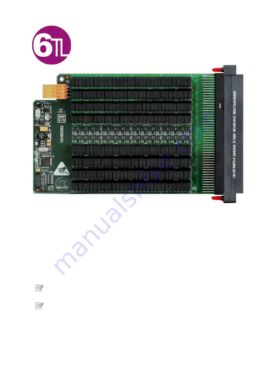
YAV90060


2-Pole 128 Cross points Matrix


This document is a technical description of the YAV90060 . 

Note

 Before you begin, complete the software and hardware installation procedures applicable to your 

application. 

Note

 the guidelines in this document are specific to the YAV90060 . The other components in the system 

might not meet the same safety ratings. Refer to the documentation of each component in the system to determine 
the safety and EMC ratings for the entire system. 

MORE INFORMATION ON OUR WEBTSITE: 

www.6tlengineering.com 


Summary of Contents for YAV90060

Page 1: ...re installation procedures applicable to your application Note the guidelines in this document are specific to the YAV90060 The other components in the system might not meet the same safety ratings Refer to the documentation of each component in the system to determine the safety and EMC ratings for the entire system MORE INFORMATION ON OUR WEBTSITE www 6tlengineering com ...

Page 2: ...T AND DIMENSIONS 4 5 MATRIX DISTRIBUTION 5 6 PINOUT FRONT 6 7 CONNECTOR PINOUT REAR 8 8 LED BEHAVIOUR 8 9 SWITCH CONFIGURATION 8 10 HARDWARE SPECIFICATIONS 9 11 OPERATION 10 11 1 PHI6 EXPLORER soft interface 10 11 2 MODE SELECTION 13 11 3 recommended matrix structures 14 12 LOW LEVEL CAN COMMANDS 15 13 ACCESSORIES 15 14 UNPACKAGING AND INSTALLING 15 ...

Page 3: ...erating failure of the lift when such failure is due to the parameters incorrect programming The product described in this manual can be configured to comply with the ruling of different countries The manufacturer does not hold any responsibility if the company installing it does not configure it according to the legal commercial or security prescriptions that may be in force in the place of insta...

Page 4: ...g two 2 Pole Matrix of 4 to 16 ports All pins are connected to a twin contact that makes it easy to configure the options of Two independent 4 x 16 Matrix One 8 x 16 Matrix One 4 x 32 Matrix Joining two or more YAV90060 modules the matrix can be increased until all test requirements are covered 4 LAYOUTAND DIMENSIONS All dimensions are in millimetres ...

Page 5: ...Pag 5 16 www 6tlengineering com 24 06 2022 YAV90060 5 MATRIX DISTRIBUTION ...

Page 6: ...04 10 Col 104 10 Col 104 10 Col 2104 10 Col 2104 11 Col 105 11 Col 105 11 Col 205 11 Col 205 12 Col 105 12 Col 105 12 Col 205 12 Col 205 13 Col 106 13 Col 106 13 Col 206 13 Col 206 14 Col 106 14 Col 106 14 Col 206 14 Col 206 15 Col 107 15 Col 107 15 Col 207 15 Col 207 16 Col 107 16 Col 107 16 Col 207 16 Col 207 17 17 17 17 18 18 18 18 19 19 19 19 20 20 20 20 21 Row A 21 Row A 21 Row E 21 Row E 22 ...

Page 7: ... 38 Col 110 38 Col 110 38 Col 210 38 Col 210 39 Col 111 39 Col 111 39 Col 211 39 Col 211 40 Col 111 40 Col 111 40 Col 211 40 Col 211 41 Col 112 41 Col 112 41 Col 212 41 Col 212 42 Col 113 42 Col 113 42 Col 213 42 Col 213 43 Col 113 43 Col 113 43 Col 213 43 Col 213 44 Col 113 44 Col 113 44 Col 213 44 Col 213 45 Col 114 45 Col 114 45 Col 214 45 Col 214 46 Col 114 46 Col 114 46 Col 214 46 Col 214 47 ...

Page 8: ...ED behaviour 9 SWITCH CONFIGURATION Switch Name Pin switch Definition of Behaviour SW1 1 2 Switches 1 and 2 set the CAN communication speed 3 to 8 The logic address is composed by 2 elements the module identification and the hardware address The module identification is set on firmware and cannot be changed The hardware address is selected by switches 3 to 8 being 3 the least significant bit LSB a...

Page 9: ... 750 mA CAN Bus operation speed 50 250 kbps Max number of active relays 80 Units Operation specifications Contact data Property Min Typ Max Units Maximum switching voltage 200 250 VDC VAC Rated current 2 A Switching power 60 62 5 W VA Minimum switching voltage 100 mV Operate time 1 3 ms Release time 3 5 ms Bounce time 1 5 ms Initial contact resistance 50 mΩ Relay contact specifications ...

Page 10: ...0060 11 OPERATION Through the PHI6 Explorer soft panel the user can interface with the YAV90060 board manually This tool is a very useful for table top debugging of test systems or system maintenance on site The image show configuration as dual 4x16 ...

Page 11: ...ww 6tlengineering com 24 06 2022 YAV90060 Configuring matrix Select the required matrix structure Two independent double pole 4 x 16 Double pole 4 x 32 Double pole 8 x 16 Configuration 4 x 32 Configuration 8 x 16 ...

Page 12: ...us in the panel will change Reset Reset button will put all relays in Open status Config tags We can give the name desired to each row column in the matrix with this function By clicking this button the panel will change its background color from grey to yellow and we will be able to change tags Exit Click this button to exit the Phi6 panel ...

Page 13: ...ee operation modes 1 Dual matrix 4x16 2 Single matrix 4x32 3 Single matrix 8x16 Operation in mode 1 keep isolated the two matrix and all the column and row tags are available to be written Operation in mode 2 will keep hidden the blocks column unions and the low row tags ...

Page 14: ...dden the blocks row unions and the lower column tags For a more efficient matrix application do not use the Y connections just the X axis The number of X access points will define the matrix dimensions and columns and the Y will be determined by the quantity of simultaneous connections ...

Page 15: ...20 24 AWG VP610138109 14 UNPACKAGINGAND INSTALLING The YAV90060 is supplied vacuum packed to avoid the intrusion of external agents during transport and storage and on an antistatic package To start using the product just remove vacuum bag carefully to avoid damage To install the YAV90060 simply insert the module on a VPC receiver vertical or horizontally according to the Receiver arrangement Once...

Page 16: ... YAV90060 module with two 4 40 UNC screws on each side of connector Tight them using a 3 32 Allen wrench at full revolutions Torque should be 0 45Nm max Finally connect the X1 rear plug of CAN bus and power supply 24VDC to start using the module ...

Reviews: