background image

Dimension GS-1008/GS-1016 Gigabit Ethernet Switch 

Troubleshooting  


3-1 

Chapter 3


Troubleshooting 

This section describes common problems you may encounter with the switch in 

your network and possible solutions.  

3.1 Introduction 

Troubleshoot the switch using the LEDs to detect problems. 

3.1.1 PWR LED 

The 

PWR

 LED on the front panel does not light up.  

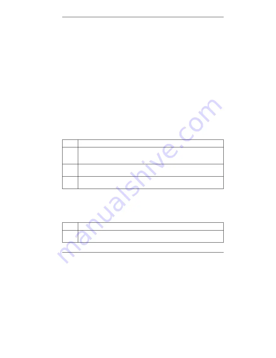
Table 3-1 Troubleshooting PWR LED 

STEPS CORRECTIVE 

ACTION 

Check the connections from your switch to the power source. Make sure you 
are using the supplied power cord and that you are using a 100 - 240V AC, 
50/60Hz power source.  

Make sure the power source is turned on and that the switch is receiving 
sufficient power. 

If these steps fail to correct the problem, contact your local distributor for 
assistance.  

3.1.2  LK/ACT or LNK/ACT LED  

The 

LK/ACT

 (or 

LNK/ACT

) LED does not light up when a device is connected.  

Table 3-2 Troubleshooting LK/ACT LED  

STEPS CORRECTIVE 

ACTION 

Verify that the attached device(s) is turned on and properly connected to your 
switch.  

Summary of Contents for ZyXEL Dimension GS-1008

Page 1: ...Dimension GS 1008 GS 1016 Gigabit Ethernet Switch User s Guide Version 1 0 May 2003 ...

Page 2: ...permission of ZyXEL Communications Corporation Published by ZyXEL Communications Corporation All rights reserved Disclaimer ZyXEL does not assume any liability arising out of the application or use of any products or software described herein Neither does it convey any license under its patent rights nor the patents rights of others ZyXEL further reserves the right to make changes in any products ...

Page 3: ... with damaged by an act of God or subjected to abnormal working conditions Note Repair or replacement as provided under this warranty is the exclusive remedy of the purchaser This warranty is in lieu of all other warranties express or implied including any implied warranty of merchantability or fitness for a particular use or purpose ZyXEL shall in no event be held liable for indirect or consequen...

Page 4: ... pursuant to Part 15 of the FCC Rules These limits are designed to provide reasonable protection against harmful interference in a commercial environment This equipment generates uses and can radiate radio frequency energy and if not installed and used in accordance with the instruction manual may cause harmful interference to radio communications Operation of this equipment in a residential area ...

Page 5: ...Dimension GS 1008 Gigabit Ethernet Switch Interference Statements and Warnings v Certifications Refer to the product page at www zyxel com ...

Page 6: ......

Page 7: ...WEB SITE FTP SITE REGULAR MAIL support zyxel com tw 886 3 578 3942 www zyxel com www europe zyxel com WORLDWIDE sales zyxel com tw 886 3 578 2439 ftp europe zyxel com ZyXEL Communications Corp 6 Innovation Road II Science Based Industrial Park Hsinchu 300 Taiwan support zyxel com 1 714 632 0882 800 255 4101 www zyxel com NORTH AMERICA sales zyxel com 1 714 632 0858 ftp zyxel com ZyXEL Communicatio...

Page 8: ......

Page 9: ...tting to Know the GS 1008 GS 1016 1 1 1 1 Features 1 1 1 2 Package Contents 1 2 1 3 Backbone Switch Network Application 1 2 Chapter 2 Hardware Description and Installation 2 1 2 1 Desktop Installation 2 1 2 2 Rack mounted Installation 2 2 2 3 Rear Panel 2 4 2 3 1 Rear Panel Power Connection 2 4 2 4 Front Panel 2 4 2 4 1 100 1000Mbps RJ 45 Auto negotiating Ports 2 5 2 4 2 Auto sensing Auto MDI MDIX...

Page 10: ... 2 4 4 Front Panel LEDs 2 6 Chapter 3 Troubleshooting 3 1 3 1 Introduction 3 1 3 1 1 PWR LED 3 1 3 1 2 LK ACT or LNK ACT LED 3 1 3 1 3 100 1000 LEDs 3 2 3 1 4 FD or FDX COL LED 3 2 3 2 Improper Network Cabling and Topology 3 2 Appendix A Product Specifications A Index C ...

Page 11: ...3 Figure 2 4 GS 1008 Rear Panel 2 4 Figure 2 5 GS 1016 Rear Panel 2 4 Figure 2 6 GS 1008 Front Panel 2 4 Figure 2 7 GS 1016 Front Panel 2 5 Figure 2 8 GS 1008 LEDs 2 6 Figure 2 9 GS 1016 LEDs 2 6 List of Tables Table 2 1 Network Cable Types 2 5 Table 2 2 Front Panel LED Descriptions 2 7 Table 3 1 Troubleshooting PWR LED 3 1 Table 3 2 Troubleshooting LK ACT LED 3 1 Table 3 3 Troubleshooting 100 100...

Page 12: ...mension GS 1008 GS 1016 Gigabit Ethernet Switch The GS 1008 GS 1016 is designed to improve your network performance with high speed data transmission over copper wire As an alternative to ATM the GS 1008 GS 1016 provides an ideal upgrade path for existing Ethernet based networks that need more bandwidth It can be installed as a backbone network while retaining existing investments in Ethernet hubs...

Page 13: ...or building environment as a high bandwidth backbone With the eight auto negotiating 100 1000Base T gigabit Ethernet ports on the GS 1008 16 on the GS 1016 you can connect the GS 1008 GS 1016 to existing Ethernet routers switches or hubs without additional expensive wiring or equipment installation Figure 1 1 GS 1008 1 1 Features Conforms to IEEE 802 3 802 3u 802 3ab and 802 3x standards Eight aut...

Page 14: ...missing or damaged please contact your local dealer Dimension Gigabit Ethernet switch Power cord Four self adhesive rubber feet This User s Guide Rack mount kit 1 3 Backbone Switch Network Application This section provides a sample of network topology in which the switch is used as a high bandwidth backbone The switch is an ideal upgrade for 100Mbps Ethernet networks You can connect existing switc...

Page 15: ...Dimension GS 1008 GS 1016 Gigabit Ethernet Switch Getting to Know the 1 3 Figure 1 2 Backbone Switch Application ...

Page 16: ......

Page 17: ...nches 8 cm at the back of the switch This is especially important for enclosed rack installations 2 1 Desktop Installation Step 1 Set the switch upside down on a study level space with a power outlet nearby Step 2 Make sure there is enough clearance around the switch to allow air circulation and the attachment of cables and the power cord Step 3 Remove the adhesive backing from the supplied rubber...

Page 18: ...hen stacking 2 2 Rack mounted Installation The switch can be mounted on an EIA standard size 19 inch rack or in a wiring closet with other equipment Follow the steps below to mount your switch on a standard EIA rack using the included rack mounting kit Step 1 Align one bracket with the holes on one side of the switch and secure it with the bracket screws Similarly attach the other bracket ...

Page 19: ...hing Mounting Brackets and Screws 2 After attaching both mounting brackets position the switch in the rack by lining up the holes in the brackets with the appropriate holes on the rack Secure the switch to the rack with the rack s mounting screws Figure 2 3 Mounting the Switch to an EIA Standard 19 inch Rack ...

Page 20: ... 4 GS 1008 Rear Panel Figure 2 5 GS 1016 Rear Panel 2 3 1 Rear Panel Power Connection Connect one end of the supplied power cord to the power receptacle on the back of the switch and the other end to the 100 240V AC 50 60Hz power source For the GS 1016 push the power switch to the ON position 2 4 Front Panel The following graphics show the front panels of the GS 1008 and the GS 1016 Figure 2 6 GS ...

Page 21: ...f duplex or full duplex mode depending on your Ethernet network 2 4 2 Auto sensing Auto MDI MDIX Ports You can connect each RJ 45 auto sensing port to a computer hub or switch using either a straight through or a crossover Ethernet cable 2 4 3 Front Panel Connections You can use unshielded twisted pair UTP or shielded twisted pair STP Ethernet cables for RJ 45 ports The following table describes t...

Page 22: ... Gigabit Ethernet Switch 2 6 Hardware Description and Installation 2 4 4 Front Panel LEDs The LEDs give real time status information The following table provides LED descriptions Figure 2 8 GS 1008 LEDs Figure 2 9 GS 1016 LEDs ...

Page 23: ...et device On A link to a 100Mbps Ethernet network is up 100 GS 1008 only Green Off The port is not connected to a 100Mbps Ethernet device On The port is connecting with an Ethernet device Blinking The port is receiving or transmitting data LK ACT or LNK ACT Green Off No Ethernet device is attached On The port is operating in full duplex mode Blinking GS 1016 The port is operating in half duplex mo...

Page 24: ......

Page 25: ...TION 1 Check the connections from your switch to the power source Make sure you are using the supplied power cord and that you are using a 100 240V AC 50 60Hz power source 2 Make sure the power source is turned on and that the switch is receiving sufficient power 3 If these steps fail to correct the problem contact your local distributor for assistance 3 1 2 LK ACT or LNK ACT LED The LK ACT or LNK...

Page 26: ...connection between the switch and your Ethernet device s 2 Verify that you are using the proper cable type and that its length does not exceed 100 meters For more information on network cable types see 2 4 3 Front Panel Connections 3 1 4 FD or FDX COL LED What is the duplex mode of the Ethernet device Table 3 4 Troubleshooting FD LED STEPS CORRECTIVE ACTION 1 The Ethernet device is connected at fu...

Page 27: ...nel Connections for more information on network cable types Cabling Length If you use longer cables than are needed transmission quality may be affected The network cables should not be longer than the limit of 100 meters Too many hubs between the computers in the network Too many hubs or repeaters between the connected computers in the network may increase the number of packet collisions or other...

Page 28: ......

Page 29: ...DI X Data Transfer Rate Fast Ethernet 100Mbps half duplex 200Mbps full duplex Gigabit Ethernet 2000Mbps full duplex Network Cables 100BASE T UTP Cat 5 100 m max EIA TIA 568 100 ohm STP 100m max 1000Base T 4 pair UTP STP Cat 5 cable EIA TIA 568 100 ohm 100m PERFORMANCE AND MANAGEMENT Back plane Non blocking full wire speed data rates GS 1008 16Gbps GS 1016 32Gbps Packet Forwarding Rate 148800PPS fo...

Page 30: ...LEDs 1000 LNK ACT Link Activity FDX COL Full duplex Per Unit Power Dimensions 440 W x 224 D x 44 H mm 19 in width rack mountable Power Supply 100 240V AC 50 60Hz internal universal power supply Power Consumption GS 1008 35W max GS 1016 60W max Operating Temperature 0ºC to 45ºC 32ºF to 113ºF Operational Humidity 10 to 90 Non condensing EMI FCC Class A CE Safety UL cUL ...

Page 31: ...port vii Copyright ii D Data path loop 3 3 Declaration of Conformity v Desktop Installation 2 1 Disclaimer ii F Faulty cables 3 3 FCC v FCC Rules iv Features 1 1 Federal Communications Commission FCC Interference Statement iv Flow Control 1 2 Front Panel 2 4 Front Panel Connections 2 5 Front Panel LED 2 6 Front Panel LED Descriptions 2 7 G Gigabit Ethernet xii H High Bandwidth Backbone 1 1 I IEEE ...

Page 32: ...ounted Installation 2 2 Rear Panel 2 4 Related Documentation xii Repair iii Return Material Authorization number iii RJ 45 ports 2 5 S Service iii Speed 3 2 Store and Forward Switching 1 2 Syntax Conventions xii T Trademarks ii Troubleshooting 100 1000 LEDs 3 2 FD LED 3 2 Troubleshooting Improper Network Cabling and Topology 3 3 LK ACT LED 3 1 PWR LED 3 1 V ventilation 2 1 Ventilation Fan 2 4 W Wa...

Reviews: