GS-4012F User’s Guide
40
Chapter 2 Hardware Installation and Connection
2.2 Mounting the Switch on a Rack
This section lists the rack mounting requirements and precautions and describes the
installation steps.
2.2.1 Rack-mounted Installation Requirements
• Two mounting brackets.
• Eight M3 flat head screws and a #2 Philips screwdriver.
• Four M5 flat head screws and a #2 Philips screwdriver.
Note:
Failure to use the proper screws may damage the unit.
2.2.1.1 Precautions
• Make sure the rack will safely support the combined weight of all the equipment it
contains.
• Make sure the position of the switch does not make the rack unstable or top-heavy. Take
all necessary precautions to anchor the rack securely before installing the unit.
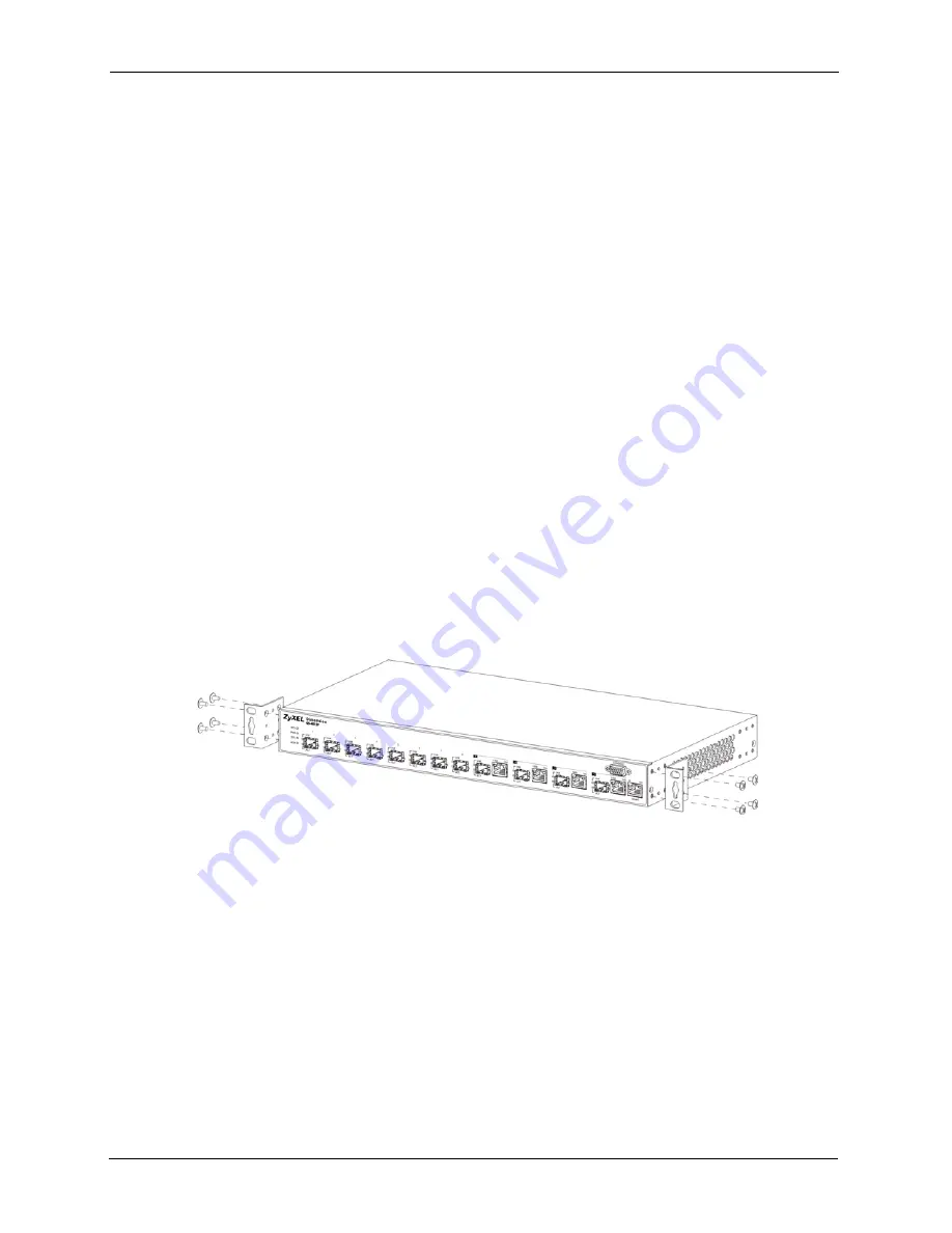
2.2.2 Attaching the Mounting Brackets to the Switch
1
Position a mounting bracket on one side of the switch, lining up the four screw holes on
the bracket with the screw holes on the side of the switch.
Figure 7
Attaching the Mounting Brackets
2
Using a #2 Philips screwdriver, install the M3 flat head screws through the mounting
bracket holes into the switch.
3
Repeat steps
to install the second mounting bracket on the other side of the
switch.
4
You may now mount the switch on a rack. Proceed to the next section.
2.2.3 Mounting the Switch on a Rack
1
Position a mounting bracket (that is already attached to the switch) on one side of the
rack, lining up the two screw holes on the bracket with the screw holes on the side of the
rack.
Summary of Contents for GS-4012F
Page 1: ...GS 4012F Ethernet Switch User s Guide Version 3 60 4 2005...
Page 19: ...GS 4012F User s Guide 18 Table of Contents...
Page 25: ...GS 4012F User s Guide 24 List of Figures...
Page 29: ...GS 4012F User s Guide 28 List of Tables...
Page 39: ...GS 4012F User s Guide 38 Chapter 1 Getting to Know Your Switch...
Page 43: ...GS 4012F User s Guide 42 Chapter 2 Hardware Installation and Connection...
Page 49: ...GS 4012F User s Guide 48 Chapter 3 Hardware Overview...
Page 63: ...GS 4012F User s Guide 62 Chapter 5 Initial Setup Example...
Page 69: ...GS 4012F User s Guide 68 Chapter 6 System Status and Port Statistics...
Page 101: ...GS 4012F User s Guide 100 Chapter 11 Spanning Tree Protocol...
Page 113: ...GS 4012F User s Guide 112 Chapter 15 Link Aggregation...
Page 117: ...GS 4012F User s Guide 116 Chapter 16 Port Authentication...
Page 125: ...GS 4012F User s Guide 124 Chapter 18 Classifier Figure 53 Classifier Example...
Page 131: ...GS 4012F User s Guide 130 Chapter 19 Policy Rule Figure 56 Policy Example...
Page 135: ...GS 4012F User s Guide 134 Chapter 20 Queuing Method...
Page 141: ...GS 4012F User s Guide 140 Chapter 21 VLAN Stacking...
Page 183: ...GS 4012F User s Guide 182 Chapter 30 VRRP...
Page 203: ...GS 4012F User s Guide 202 Chapter 32 Access Control...
Page 205: ...GS 4012F User s Guide 204 Chapter 33 Diagnostic...
Page 219: ...GS 4012F User s Guide 218 Chapter 38 Routing Table...
Page 267: ...GS 4012F User s Guide 266 Chapter 40 Command Examples...
Page 277: ...GS 4012F User s Guide 276 Chapter 41 IEEE 802 1Q Tagged VLAN Commands...
Page 287: ...GS 4012F User s Guide 286 Chapter 42 Troubleshooting...
Page 291: ...GS 4012F User s Guide 290 Product Specifications...


