background image

 Chapter 1 Getting to Know Your Switch

GS-2024 User’s Guide

31

1.1.4  IEEE 802.1Q VLAN Application Examples

A VLAN (Virtual Local Area Network) allows a physical network to be partitioned into 
multiple logical networks. Stations on a logical network belong to one group. A station can 
belong to more than one group. With VLAN, a station cannot directly talk to or hear from 
stations that are not in the same group(s) unless such traffic first goes through a router.
For more information on VLANs, refer to 

Chapter 8 on page 77

.

1.1.4.1  Tag-based VLAN Example

Ports in the same VLAN group share the same frame broadcast domain thus increase network 
performance through reduced broadcast traffic. VLAN groups can be modified at any time by 
adding, moving or changing ports without any re-cabling. 
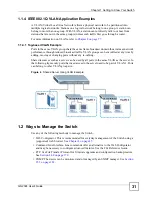
Shared resources such as a server can be used by all ports in the same VLAN as the server. In 
the following figure only ports that need access to the server need to be part of VLAN 1. Ports 
can belong to other VLAN groups too.

Figure 4   

Shared Server Using VLAN Example 

1.2  Ways to Manage the Switch

Use any of the following methods to manage the Switch.

• Web Configurator. This is recommended for everyday management of the Switch using a 

(supported) web browser. See 

Chapter 4 on page 45

.

• Command Line Interface. Line commands offer an alternative to the Web Configurator 

and may be necessary to configure advanced features. See the CLI Reference Guide.

• FTP. Use File Transfer Protocol for firmware upgrades and configuration backup/restore. 

See 

Section 24.8 on page 179

.

• SNMP. The device can be monitored and/or managed by an SNMP manager. See 

Section 

25.3 on page 182

.

Summary of Contents for Dimension GS-2024

Page 1: ...xel com GS 2024 Layer 2 Ethernet Switch User s Guide Version 3 80 06 2008 Edition 1 DEFAULT LOGIN IP Address http 192 168 0 1 Out of band MGMT port http 192 168 1 1 In band ports User Name admin Password 1234 ...

Page 2: ......

Page 3: ...or support documents ZyXEL Web Site Please refer to www zyxel com for additional support documentation and product certifications User Guide Feedback Help us help you Send all User Guide related comments questions or suggestions for improvement to the following address or use e mail instead Thank you The Technical Writing Team ZyXEL Communications Corp 6 Innovation Road II Science Based Industrial...

Page 4: ...eld choices are all in bold font A key stroke is denoted by square brackets and uppercase text for example ENTER means the enter or return key on your keyboard Enter means for you to type one or more characters and then press the ENTER key Select or choose means for you to use one of the predefined choices A right angle bracket within a screen name denotes a mouse click For example Maintenance Log...

Page 5: ...uide 5 Icons Used in Figures Figures in this User s Guide may use the following generic icons The Switch icon is not an exact representation of your device The Switch Computer Notebook computer Server DSLAM Firewall Telephone Switch Router ...

Page 6: ... correct ports Place connecting cables carefully so that no one will step on them or stumble over them Always disconnect all cables from this device before servicing or disassembling Use ONLY an appropriate power adaptor or cord for your device Connect it to the right supply voltage for example 110V AC in North America or 230V AC in Europe Do NOT allow anything to rest on the power adaptor or cord...

Page 7: ...Safety Warnings GS 2024 User s Guide 7 This product is recyclable Dispose of it properly ...

Page 8: ...Safety Warnings GS 2024 User s Guide 8 ...

Page 9: ...7 Basic Setting 63 Advanced Setup 75 VLAN 77 Static MAC Forward Setup 89 Spanning Tree Protocol 91 Bandwidth Control 105 Broadcast Storm Control 107 Mirroring 109 Link Aggregation 111 Port Authentication 117 Port Security 121 Queuing Method 123 Multicast 125 Authentication Accounting 139 Loop Guard 153 IP Application 157 Static Route 159 Differentiated Services 163 DHCP 167 Management 173 Maintena...

Page 10: ...ontents Overview GS 2024 User s Guide 10 MAC Table 211 ARP Table 213 Configure Clone 215 Troubleshooting Product Specifications 217 Troubleshooting 219 Product Specifications 223 Appendices and Index 231 ...

Page 11: ... 3 High Performance Switching Example 30 1 1 4 IEEE 802 1Q VLAN Application Examples 31 1 2 Ways to Manage the Switch 31 1 3 Good Habits for Managing the Switch 32 Chapter 2 Hardware Installation and Connection 33 2 1 Freestanding Installation 33 2 2 Mounting the Switch on a Rack 34 2 2 1 Rack mounted Installation Requirements 34 2 2 2 Attaching the Mounting Brackets to the Switch 34 2 2 3 Mountin...

Page 12: ...Lockout 51 4 6 Resetting the Switch 51 4 6 1 Reload the Configuration File 51 4 7 Logging Out of the Web Configurator 52 4 8 Help 52 Chapter 5 Initial Setup Example 53 5 1 Overview 53 5 1 1 Creating a VLAN 53 5 1 2 Setting Port VID 54 5 1 3 Configuring Switch Management IP Address 55 Chapter 6 System Status and Port Statistics 57 6 1 Overview 57 6 2 Port Status Summary 57 6 2 1 Status Port Details...

Page 13: ... a Static VLAN 81 8 5 4 Configure VLAN Port Settings 82 8 6 Port based VLAN Setup 84 8 6 1 Configure a Port based VLAN 84 Chapter 9 Static MAC Forward Setup 89 9 1 Overview 89 9 2 Configuring Static MAC Forwarding 89 Chapter 10 Spanning Tree Protocol 91 10 1 STP RSTP Overview 91 10 1 1 STP Terminology 91 10 1 2 How STP Works 92 10 1 3 STP Port States 92 10 1 4 Multiple STP 93 10 2 Spanning Tree Pr...

Page 14: ...n ID 112 14 3 Link Aggregation Status 112 14 4 Link Aggregation Setting 113 14 5 Link Aggregation Control Protocol 114 14 6 Static Trunking Example 115 Chapter 15 Port Authentication 117 15 1 Port Authentication Overview 117 15 1 1 IEEE 802 1x Authentication 117 15 2 Port Authentication Configuration 118 15 2 1 Activate IEEE 802 1x Security 118 Chapter 16 Port Security 121 16 1 About Port Security...

Page 15: ...up Configuration 134 18 8 1 MVR Configuration Example 135 Chapter 19 Authentication Accounting 139 19 1 Authentication Authorization and Accounting 139 19 1 1 Local User Accounts 139 19 1 2 RADIUS and TACACS 140 19 2 Authentication and Accounting Screens 140 19 2 1 RADIUS Server Setup 140 19 2 2 TACACS Server Setup 142 19 2 3 Authentication and Accounting Setup 144 19 2 4 Vendor Specific Attribute...

Page 16: ... 167 23 2 DHCP Status 167 23 3 DHCP Relay 168 23 3 1 DHCP Relay Agent Information 168 23 3 2 Configuring DHCP Global Relay 169 23 3 3 Global DHCP Relay Configuration Example 170 23 4 Configuring DHCP VLAN Settings 170 23 4 1 Example DHCP Relay for Two VLANs 172 Part V Management 173 Chapter 24 Maintenance 175 24 1 The Maintenance Screen 175 24 2 Load Factory Default 176 24 3 Save Configuration 176...

Page 17: ...tch 192 25 6 1 Requirements for Using SSH 192 25 7 Introduction to HTTPS 192 25 8 HTTPS Example 193 25 8 1 Internet Explorer Warning Messages 193 25 8 2 Netscape Navigator Warning Messages 194 25 8 3 The Main Screen 194 25 9 Service Port Access Control 195 25 10 Remote Management 196 Chapter 26 Diagnostic 199 26 1 Diagnostic 199 Chapter 27 Syslog 201 27 1 Syslog Overview 201 27 2 Syslog Setup 201 ...

Page 18: ...15 31 1 Configure Clone 215 Part VI Troubleshooting Product Specifications 217 Chapter 32 Troubleshooting 219 32 1 Power Hardware Connections and LEDs 219 32 2 Switch Access and Login 220 Chapter 33 Product Specifications 223 Part VII Appendices and Index 231 Appendix A Pop up Windows JavaScripts and Java Permissions 233 Appendix B IP Addresses and Subnetting 241 Appendix C Legal Information 249 A...

Page 19: ... Web Configurator Logout Screen 52 Figure 19 Initial Setup Network Example VLAN 53 Figure 20 Initial Setup Network Example Port VID 54 Figure 21 Initial Setup Example Management IP Address 55 Figure 22 Status 57 Figure 23 Status Port Details 59 Figure 24 Basic Setting System Info 64 Figure 25 Basic Setting General Setup 65 Figure 26 Basic Setting Switch Setup 68 Figure 27 Basic Setting IP Setup 70...

Page 20: ... Application Port Authentication 118 Figure 58 Advanced Application Port Authentication 802 1x 119 Figure 59 Advanced Application Port Security 122 Figure 60 Advanced Application Queuing Method 124 Figure 61 Advanced Application Multicast 126 Figure 62 Advanced Application Multicast Multicast Setting 127 Figure 63 Advanced Application Multicast Multicast Setting IGMP Snooping VLAN 129 Figure 64 Ad...

Page 21: ...ss Control 181 Figure 102 SNMP Management Model 182 Figure 103 Management Access Control SNMP 186 Figure 104 Management Access Control SNMP Trap Group 188 Figure 105 Management Access Control Logins 190 Figure 106 SSH Communication Example 191 Figure 107 How SSH Works 191 Figure 108 HTTPS Implementation 193 Figure 109 Security Alert Dialog Box Internet Explorer 193 Figure 110 Security Certificate ...

Page 22: ...ternet Options Privacy 235 Figure 131 Pop up Blocker Settings 235 Figure 132 Internet Options Security 236 Figure 133 Security Settings Java Scripting 237 Figure 134 Security Settings Java 237 Figure 135 Java Sun 238 Figure 136 Mozilla Firefox Tools Options 239 Figure 137 Mozilla Firefox Content Security 239 Figure 138 Network Number and Host ID 242 Figure 139 Subnetting Example Before Subnetting ...

Page 23: ...rding 90 Table 20 STP Path Costs 92 Table 21 STP Port States 92 Table 22 Advanced Application Spanning Tree Protocol Configuration 96 Table 23 Advanced Application Spanning Tree Protocol RSTP 97 Table 24 Advanced Application Spanning Tree Protocol Status RSTP 99 Table 25 Advanced Application Spanning Tree Protocol MSTP 101 Table 26 Advanced Application Spanning Tree Protocol Status MSTP 103 Table ...

Page 24: ...Guard 155 Table 54 IP Application Static Routing 160 Table 55 Default DSCP IEEE 802 1p Mapping 164 Table 56 IP Application DiffServ 165 Table 57 IP Application DHCP Status 168 Table 58 Relay Agent Information 168 Table 59 IP Application DHCP Global 169 Table 60 IP Application DHCP VLAN 171 Table 61 Management Maintenance 175 Table 62 Filename Conventions 179 Table 63 General Commands for GUI based...

Page 25: ...itching Specifications 226 Table 90 Standards Supported 227 Table 91 Console Dial Backup Port Pin Assignments 229 Table 92 Ethernet Cable Pin Assignments 229 Table 93 IP Address Network Number and Host ID Example 242 Table 94 Subnet Masks 243 Table 95 Maximum Host Numbers 243 Table 96 Alternative Subnet Mask Notation 243 Table 97 Subnet 1 245 Table 98 Subnet 2 246 Table 99 Subnet 3 246 Table 100 S...

Page 26: ...List of Tables GS 2024 User s Guide 26 ...

Page 27: ...27 PART I Introduction Getting to Know Your Switch 29 Hardware Installation and Connection 33 Hardware Overview 37 ...

Page 28: ...28 ...

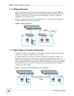
Page 29: ... terminal emulator program on the console port or third party SNMP management See Chapter 33 on page 223 for a full list of software features available on the Switch 1 1 1 Backbone Application The Switch is an ideal solution for small networks where rapid growth can be expected in the near future The Switch can be used standalone for a group of heavy traffic users You can connect computers and ser...

Page 30: ...ridging Application 1 1 3 High Performance Switching Example The Switch is ideal for connecting two networks that need high bandwidth In the following example use trunking to connect these two networks Switching to higher speed LANs such as ATM Asynchronous Transmission Mode is not feasible for most people due to the expense of replacing all existing Ethernet cables and adapter cards restructuring...

Page 31: ...y time by adding moving or changing ports without any re cabling Shared resources such as a server can be used by all ports in the same VLAN as the server In the following figure only ports that need access to the server need to be part of VLAN 1 Ports can belong to other VLAN groups too Figure 4 Shared Server Using VLAN Example 1 2 Ways to Manage the Switch Use any of the following methods to man...

Page 32: ...of characters such as numbers and letters Write down the password and put it in a safe place Back up the configuration and make sure you know how to restore it Restoring an earlier working configuration may be useful if the device becomes unstable or even crashes If you forget your password you will have to reset the Switch to its factory default settings If you backed up an earlier configuration ...

Page 33: ...ables Make sure there is a power outlet nearby 3 Make sure there is enough clearance around the Switch to allow air circulation and the attachment of cables and the power cord 4 Remove the adhesive backing from the rubber feet 5 Attach the rubber feet to each corner on the bottom of the Switch These rubber feet help protect the Switch from shock or vibration and ensure space between devices when s...

Page 34: ...ead screws and a 2 Philips screwdriver 1 Failure to use the proper screws may damage the unit 2 2 1 1 Precautions Make sure the rack will safely support the combined weight of all the equipment it contains Make sure the position of the Switch does not make the rack unstable or top heavy Take all necessary precautions to anchor the rack securely before installing the unit 2 2 2 Attaching the Mounti...

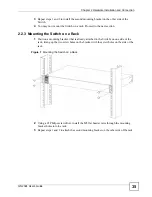
Page 35: ...g the Switch on a Rack 1 Position a mounting bracket that is already attached to the Switch on one side of the rack lining up the two screw holes on the bracket with the screw holes on the side of the rack Figure 7 Mounting the Switch on a Rack 2 Using a 2 Philips screwdriver install the M5 flat head screws through the mounting bracket holes into the rack 3 Repeat steps 1 and 2 to attach the secon...

Page 36: ...Chapter 2 Hardware Installation and Connection GS 2024 User s Guide 36 ...

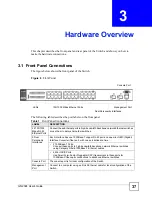
Page 37: ... ports to high bandwidth backbone network Ethernet switches or use them to daisy chain other switches 2 Dual Personality Interfaces Each interface has one 1000Base T copper RJ 45 port and one mini GBIC Gigabit Interface Converter fiber port with one port active at a time 2 1000Base T Ports Connect these ports to high bandwidth backbone network Ethernet switches using Category 5 5e 6 1000Base T Eth...

Page 38: ...uto negotiation or turns off this feature the Switch determines the connection speed by detecting the signal on the cable and using half duplex mode When the Switch s auto negotiation is turned off a Gigabit port uses the pre configured speed and duplex mode when making a connection thus requiring you to make sure that the settings of the peer Ethernet port are the same in order to connect 3 1 1 1...

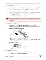
Page 39: ... switches with different types of fiber optic connectors Type SFP connection interface Connection speed 1 Gigabit per second Gbps 1 To avoid possible eye injury do not look into an operating fiber optic module s connectors 3 1 2 1 1 Transceiver Installation Use the following steps to install a mini GBIC transceiver SFP or XFP module 1 Insert the transceiver into the slot with the exposed section o...

Page 40: ...bits 1 stop bit No flow control Connect the male 9 pin end of the RS 232 console cable to the console port of the Switch Connect the female end to a serial port COM1 COM2 or other COM port of your computer 3 1 4 Management Port The MGMT management port is used for local management Connect directly to this port using an Ethernet cable You can configure the Switch via Telnet or the web configurator ...

Page 41: ... Green On The system is turned on Off The system is off SYS Green Blinking The system is rebooting and performing self diagnostic tests On The system is on and functioning properly Off The power is off or the system is not ready or is malfunctioning ALM Red On There is a hardware failure Off The system is functioning normally Gigabit Ports LNK ACT Green Blinking The system is transmitting receivin...

Page 42: ... to from an Ethernet device On The port is connected at 10Mbps Off The port is not connected at 10Mbps or to an Ethernet device 100 Amber Blinking The system is transmitting receiving to from an Ethernet device On The port is connected at 100Mbps Off The port is not connected at 100Mbps or to an Ethernet device Table 2 LED Descriptions continued LED COLOR STATUS DESCRIPTION ...

Page 43: ...43 PART II Basic Configuration The Web Configurator 45 Initial Setup Example 53 System Status and Port Statistics 57 Basic Setting 63 ...

Page 44: ...44 ...

Page 45: ...wser pop up windows from your device Web pop up blocking is enabled by default in Windows XP SP Service Pack 2 JavaScript enabled by default Java permissions enabled by default 4 2 System Login 1 Start your web browser 2 Type http and the IP address of the Switch for example the default management IP address is 192 168 1 1 through an in band non MGMT port and 192 168 0 1 through the MGMT port in t...

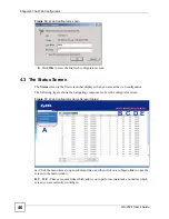
Page 46: ...s when you access the web configurator The following figure shows the navigating components of a web configurator screen Figure 15 Web Configurator Home Screen Status A Click the menu items to open submenu links and then click on a submenu link to open the screen in the main window B C D E These are quick links which allow you to perform certain tasks no matter which screen you are currently worki...

Page 47: ...n 24 3 on page 176 for information on saving your settings to a specific configuration file C Click this link to go to the status page of the Switch D Click this link to log out of the web configurator E Click this link to display web help pages The help pages provide descriptions for all of the configuration screens In the navigation panel click a main link to reveal a list of submenu links Table...

Page 48: ...Static Routing DiffServ DHCP Status DHCP Relay VLAN Setting Maintenance Firmware Upgrade Restore Configuration Backup Configuration Access Control SNMP Trap Group Logins Service Access Control Remote Management Diagnostic Syslog Setup Syslog Server Setup Clustering Management Status Clustering Management Configuration MAC Table ARP Table Configure Clone Table 5 Navigation Panel Links LINK DESCRIPT...

Page 49: ...gure various multicast features and create multicast VLANs Auth and Acct This link takes you to screens where you can configure authentication and accounting services via external servers The external servers can be either RADIUS Remote Authentication Dial In User Service or TACACS Terminal Access Controller Access Control System Plus Loop Guard This link takes you to a screen where you can config...

Page 50: ...ttings in the run time memory are lost when the Switch s power is turned off Click the Save link in the upper right hand corner of the web configurator to save your configuration to nonvolatile memory Nonvolatile memory refers to the Switch s storage that remains even if the Switch s power is turned off Use the Save link when you are done with a configuration session ARP Table This link takes you ...

Page 51: ...ration file or reset the Switch back to the factory defaults 4 6 1 Reload the Configuration File Uploading the factory default configuration file replaces the current configuration file with the factory default configuration file This means that you will lose all previous configurations and the speed of the console port will be reset to the default of 9600 bps with 8 data bit no parity one stop bi...

Page 52: ...n for security reasons Figure 18 Web Configurator Logout Screen 4 8 Help The web configurator s online help has descriptions of individual screens and some supplementary information Click the Help link from a web configurator screen to view an online help description of that screen Bootbase Version V0 6 05 18 2004 15 28 28 AM Size 32 Mbytes DRAM POST Testing 32768K OK DRAM Test SUCCESS FLASH Intel...

Page 53: ...D Configure the switch IP management address 5 1 1 Creating a VLAN VLANs confine broadcast frames to the VLAN group in which the port s belongs You can do this with port based VLAN or tagged static VLAN with fixed port members In this example you want to configure port 10 as a member of VLAN 2 Figure 19 Initial Setup Network Example VLAN 1 Click Advanced Application and VLAN in the navigation pane...

Page 54: ...t 10 to be a permanent member of the VLAN only 4 To ensure that VLAN unaware devices such as computers and hubs can receive frames properly clear the TX Tagging check box to set the switch to remove VLAN tags before sending 5 Click Add to save the settings 5 1 2 Setting Port VID Use PVID to add a tag to incoming untagged frames received on that port so that the frames are forwarded to the VLAN gro...

Page 55: ...nt IP address of the switch is 192 168 1 1 You can configure another IP address in a different subnet for management purposes The following figure shows an example Figure 21 Initial Setup Example Management IP Address 1 Connect your computer to any Ethernet port on the switch Make sure your computer is in the same subnet as the switch 2 Open your web browser and enter 192 168 1 1 the default IP ad...

Page 56: ...e the related fields in the IP Setup screen For the VLAN2 network enter 192 168 2 1 as the IP address and 255 255 255 0 as the subnet mask 5 In the VID field enter the ID of the VLAN group to which you want this management IP address to belong This is the same as the VLAN ID you configure in the Static VLAN screen 6 Click Add ...

Page 57: ...ing statistical details 6 2 Port Status Summary To view the port statistics click Status in all web configurator screens to display the Status screen as shown next Figure 22 Status The following table describes the labels in this screen Table 6 Status LABEL DESCRIPTION Port This identifies the Ethernet port Click a port number to display the Port Details screen refer to Figure 23 on page 59 Name T...

Page 58: ...plays FORWARDING if the link is up otherwise it displays STOP LACP This fields displays whether LACP Link Aggregation Control Protocol has been enabled on the port TxPkts This field shows the number of transmitted frames on this port RxPkts This field shows the number of received frames on this port Errors This field shows the number of received errors on this port Tx KB s This field shows the tra...

Page 59: ...r H for half duplex It also shows the cable type Copper or Fiber State If STP Spanning Tree Protocol is enabled this field displays the STP state of the port See Section 10 1 3 on page 92 for more information If STP is disabled this field displays FORWARDING if the link is up otherwise it displays STOP LACP This field shows if LACP is enabled on this port or not TxPkts This field shows the number ...

Page 60: ...owing fields display information on collisions while transmitting Single This is a count of successfully transmitted packets for which transmission is inhibited by exactly one collision Multiple This is a count of successfully transmitted packets for which transmission was inhibited by more than one collision Excessive This is a count of packets for which transmission failed due to excessive colli...

Page 61: ...is field shows the number of packets including bad packets received that were between 512 and 1023 octets in length 1024 1518 This field shows the number of packets including bad packets received that were between 1024 and 1518 octets in length Giant This field shows the number of packets dropped because they were bigger than the maximum frame size Table 7 Status Port Details continued LABEL DESCR...

Page 62: ...Chapter 6 System Status and Port Statistics GS 2024 User s Guide 62 ...

Page 63: ...o allows you to set the system time manually or get the current time and date from an external server when you turn on your Switch The real time is then displayed in the Switch logs The Switch Setup screen allows you to set up and configure global Switch features The IP Setup screen allows you to configure a Switch IP address in each routing domain subnet mask s and DNS domain name server for mana...

Page 64: ...perature CPU PHY and MAC refer to the location of the temperature sensors on the Switch printed circuit board Current This shows the current temperature at this sensor MAX This field displays the maximum temperature measured at this sensor MIN This field displays the minimum temperature measured at this sensor Threshold This field displays the upper temperature limit at this sensor Status This fie...

Page 65: ... is functioning above the minimum speed Error indicates that this fan is functioning below the minimum speed Voltage V The power supply for each voltage has a sensor that is capable of detecting and reporting if the voltage falls out of the tolerance range Current This is the current voltage reading MAX This field displays the maximum voltage measured at this point MIN This field displays the mini...

Page 66: ...ked for 60 seconds Please wait Current Time This field displays the time you open this menu or refresh the menu New Time hh min ss Enter the new time in hour minute and second format The new time then appears in the Current Time field after you click Apply Current Date This field displays the date you open this menu New Date yyyy mm dd Enter the new date in year month and day format The new date t...

Page 67: ...tup in the navigation panel to display the screen as shown The VLAN setup screens change depending on whether you choose 802 1Q or Port Based in the VLAN Type field in this screen Refer to the chapter on VLAN End Date Configure the day and time when Daylight Saving Time ends if you selected Daylight Saving Time The time field uses the 24 hour format Here are a couple of examples Daylight Saving Ti...

Page 68: ... Timer sets the duration of the Join Period timer for GVRP in milliseconds Each port has a Join Period timer The allowed Join Time range is between 100 and 65535 milliseconds the default is 200 milliseconds See Chapter 8 on page 77 for more background information Leave Timer Leave Time sets the duration of the Leave Period timer for GVRP in milliseconds Each port has a single Leave Period timer Le...

Page 69: ...fic that is especially sensitive to jitter jitter is the variations in delay Level 5 Typically used for video that consumes high bandwidth and is sensitive to jitter Level 4 Typically used for controlled load latency sensitive traffic such as SNA Systems Network Architecture transactions Level 3 Typically used for excellent effort or better than best effort and would include important business tra...

Page 70: ...Chapter 7 Basic Setting GS 2024 User s Guide 70 Figure 27 Basic Setting IP Setup ...

Page 71: ... 192 168 1 1 IP Subnet Mask Enter the IP subnet mask of your Switch in dotted decimal notation for example 255 255 255 0 Default Gateway Enter the IP address of the default outgoing gateway in dotted decimal notation for example 192 168 1 254 VID Enter the VLAN identification number associated with the Switch IP address VID is the VLAN ID of the CPU and is used for management only The default is 1...

Page 72: ...o save the new rule to the Switch s run time memory It then displays in the summary table at the bottom of the screen Cancel Click Cancel to reset the fields Index This field displays the index number of an entry Click an index number to edit the rule IP Address This field displays the IP address IP Subnet Mask This field displays the subnet mask VID This field displays the VLAN identification num...

Page 73: ... speed by detecting the signal on the cable and using half duplex mode When the Switch s auto negotiation is turned off a port uses the pre configured speed and duplex mode when making a connection thus requiring you to make sure that the settings of the peer port are the same in order to connect Flow Control A concentration of traffic on a port decreases port bandwidth and overflows buffer memory...

Page 74: ...Chapter 7 Basic Setting GS 2024 User s Guide 74 ...

Page 75: ...Forward Setup 89 Spanning Tree Protocol 91 Bandwidth Control 105 Broadcast Storm Control 107 Mirroring 109 Link Aggregation 111 Port Authentication 117 Port Security 121 Queuing Method 123 Multicast 125 Authentication Accounting 139 Loop Guard 153 ...

Page 76: ...76 ...

Page 77: ...The remaining twelve bits define the VLAN ID giving a possible maximum number of 4 096 VLANs Note that user priority and VLAN ID are independent of each other A frame with VID VLAN Identifier of null 0 is called a priority frame meaning that only the priority level is significant and the default VID of the ingress port is given as the VID of the frame Of the 4096 possible VIDs a VID of 0 is used t...

Page 78: ...VLAN groups beyond the local Switch Please refer to the following table for common IEEE 802 1Q VLAN terminology Table 13 IEEE 802 1Q VLAN Terminology VLAN PARAMETER TERM DESCRIPTION VLAN Type Permanent VLAN This is a static VLAN created manually Dynamic VLAN This is a VLAN configured by a GVRP registration deregistration process VLAN Administrative Control Registration Fixed Fixed registration por...

Page 79: ...er with VLAN Trunking enabled on a port s in each intermediary switch you only need to create VLAN groups in the end devices A and B C D and E automatically allow frames with VLAN group tags 1 and 2 VLAN groups that are unknown to those switches to pass through their VLAN trunking port s Figure 29 Port VLAN Trunking 8 4 Select the VLAN Type Select a VLAN type in the Basic Setting Switch Setup scre...

Page 80: ...re 32 Advanced Application VLAN VLAN Detail Table 14 Advanced Application VLAN VLAN Status LABEL DESCRIPTION The Number of VLAN This is the number of VLANs configured on the Switch Index This is the VLAN index number Click on an index number to view more VLAN details VID This is the VLAN identification number that was configured in the Static VLAN screen Elapsed Time This field shows how long it h...

Page 81: ...Detail LABEL DESCRIPTION VLAN Status Click this to go to the VLAN Status screen VID This is the VLAN identification number that was configured in the Static VLAN screen Port Number This column displays the ports that are participating in a VLAN A tagged port is marked as T an untagged port is marked as U and ports not participating in a VLAN are marked as Elapsed Time This field shows how long it ...

Page 82: ... Changes in this row are copied to all the ports as soon as you make them Control Select Normal for the port to dynamically join this VLAN group using GVRP This is the default selection Select Fixed for the port to be a permanent member of this VLAN group Select Forbidden if you want to prohibit the port from joining this VLAN group Tagging Select TX Tagging if you want the port to tag all outgoin...

Page 83: ...ied to all the ports as soon as you make them Ingress Check If this check box is selected for a port the Switch discards incoming frames for VLANs that do not include this port in its member set Clear this check box to disable ingress filtering PVID Enter a number between 1and 4094 as the port VLAN ID GVRP Select this check box to allow GVRP on this port Acceptable Frame Type Specify the type of f...

Page 84: ...nt port forms a VLAN with all Ethernet ports 8 6 1 Configure a Port based VLAN Select Port Based as the VLAN Type in the Switch Setup screen and then click VLAN from the navigation panel to display the following screen Select either All Connected or Port Isolated from the drop down list depending on your VLAN and VLAN security requirements If VLAN members need to communicate directly with each oth...

Page 85: ...Chapter 8 VLAN GS 2024 User s Guide 85 Figure 35 Advanced Application VLAN Port Based VLAN Setup All Connected The following screen shows users on a port based port isolated VLAN configuration ...

Page 86: ... outgoing port is selected This option is the most limiting but also the most secure After you make your selection click Apply top right of screen to display the screens as mentioned above You can still customize these settings by adding deleting incoming or outgoing ports but you must also click Apply at the bottom of the screen Incoming These are the ingress ports an ingress port is an incoming ...

Page 87: ...VLAN with all Ethernet ports If it does not form a VLAN with a particular port then the Switch cannot be managed from that port Apply Click Apply to save your changes to the Switch s run time memory The Switch loses these changes if it is turned off or loses power so use the Save link on the top navigation panel to save your changes to the non volatile memory when you are done configuring Cancel C...

Page 88: ...Chapter 8 VLAN GS 2024 User s Guide 88 ...

Page 89: ...C address table Static MAC addresses do not age out When you set up static MAC address rules you are setting static MAC addresses for a port This may reduce the need for broadcasting Static MAC address forwarding together with port security allows only computers in the MAC address table on a port to access the Switch See Chapter 16 on page 121 for more information on port security Click Advanced A...

Page 90: ...loses power so use the Save link on the top navigation panel to save your changes to the non volatile memory when you are done configuring Cancel Click Cancel to begin configuring this screen afresh Clear Click Clear to reset the fields to the factory defaults Index Click an index number to modify a static MAC address rule for a port Active This field displays whether this static MAC address forwa...

Page 91: ...ches in your network to ensure that only one path exists between any two stations on the network The Switch uses IEEE 802 1w RSTP Rapid Spanning Tree Protocol that allows faster convergence of the spanning tree than STP while also being backwards compatible with STP only aware bridges In RSTP topology change information is directly propagated throughout the network from the device that generates t...

Page 92: ...re switches exchange Bridge Protocol Data Units BPDUs periodically When the bridged LAN topology changes a new spanning tree is constructed Once a stable network topology has been established all bridges listen for Hello BPDUs Bridge Protocol Data Units transmitted from the root bridge If a bridge does not get a Hello BPDU after a predefined interval Max Age the bridge assumes that the link to the...

Page 93: ...e spanning tree Load balancing is possible as traffic from different VLANs can use distinct paths in a region 10 1 4 1 MSTP Network Example The following figure shows a network example where two VLANs are configured on the two switches If the switches are using STP or RSTP the link for VLAN 2 will be blocked as STP and RSTP allow only one link in the network and block the redundant link Figure 38 ...

Page 94: ...ased by one Internal path cost of paths within this region is increased by one when BPDUs traverse the region Devices that belong to the same MST region are configured to have the same MSTP configuration identification settings These include the following parameters Name of the MST region Revision level as the unique number for the MST region VLAN to MST Instance mapping 10 1 4 3 MST Instance An M...

Page 95: ...mbers of an MST instance are members of the CIST In an MSTP enabled network there is only one CIST that runs between MST regions and single spanning tree devices A network may contain multiple MST regions and other network segments running RSTP Figure 41 MSTP and Legacy RSTP Network Example 10 2 Spanning Tree Protocol Status Screen The Spanning Tree Protocol status screen changes depending on what...

Page 96: ...ing table describes the labels in this screen 10 4 Configure Rapid Spanning Tree Protocol Use this screen to configure RSTP settings see Section 10 1 on page 91 for more information on RSTP Click RSTP in the Advanced Application Spanning Tree Protocol screen Table 22 Advanced Application Spanning Tree Protocol Configuration LABEL DESCRIPTION Spanning Tree Mode You can activate one of the STP modes...

Page 97: ...o enable RSTP on the Switch Bridge Priority Bridge priority is used in determining the root switch root port and designated port The switch with the highest priority lowest numeric value becomes the STP root switch If all switches have the same priority the switch with the lowest MAC address will then become the root switch Select a value from the drop down list box The lower the numeric value you...

Page 98: ... 4 to 30 seconds As a general rule Note 2 Forward Delay 1 Max Age 2 Hello Time 1 Port This field displays the port number Settings in this row apply to all ports Use this row only if you want to make some settings the same for all ports Use this row first to set the common settings and then make adjustments on a port by port basis Note Changes in this row are copied to all the ports as soon as you...

Page 99: ...e for Root and Our Bridge if the Switch is the root switch Hello Time second This is the time interval in seconds at which the root switch transmits a configuration message The root bridge determines Hello Time Max Age and Forwarding Delay Max Age second This is the maximum time in seconds a switch can wait without receiving a configuration message before attempting to reconfigure Forwarding Delay...

Page 100: ...Chapter 10 Spanning Tree Protocol GS 2024 User s Guide 100 Figure 46 Advanced Application Spanning Tree Protocol MSTP ...

Page 101: ...tarts to forward frames In addition each port needs time to listen for conflicting information that would make it return to a blocking state otherwise temporary data loops might result The allowed range is 4 to 30 seconds As a general rule Note 2 Forward Delay 1 Max Age 2 Hello Time 1 Maximum hops Enter the number of hops between 1 and 255 in an MSTP region before the BPDU is discarded and the por...

Page 102: ... you make them Active Select this check box to add this port to the MST instance Priority Configure the priority for each port here Priority decides which port should be disabled when more than one port forms a loop in the Switch Ports with a higher priority numeric value are disabled first The allowed range is between 0 and 255 and the default value is 128 Path Cost Path cost is the cost of trans...

Page 103: ...ge is this Switch This Switch may also be the root bridge Bridge ID This is the unique identifier for this bridge consisting of bridge priority plus MAC address This ID is the same for Root and Our Bridge if the Switch is the root switch Hello Time second This is the time interval in seconds at which the root switch transmits a configuration message Max Age second This is the maximum time in secon...

Page 104: ...spanning tree was last reconfigured Instance These fields display the MSTI to VLAN mapping In other words which VLANs run on each spanning tree instance Instance This field displays the MSTI ID VLAN This field displays which VLANs are mapped to an MSTI MSTI Select the MST instance settings you want to view Bridge Root refers to the base of the MST instance Our Bridge is this Switch This Switch may...

Page 105: ...th Control screen 11 1 Bandwidth Control Overview Bandwidth control means defining a maximum allowable bandwidth for incoming traffic flows on a port 11 2 Bandwidth Control Setup Click Advanced Application Bandwidth Control in the navigation panel to bring up the screen as shown next Figure 48 Advanced Application Bandwidth Control ...

Page 106: ...ver the maximum allowable bandwidth on a port A concentration of traffic on a port decreases port bandwidth and overflows buffer memory causing packet discards and frame losses Flow Control is used to regulate transmission of signals to match the bandwidth of the receiving port The switch uses IEEE802 3x flow control in full duplex mode and backpressure flow control in half duplex mode IEEE802 3x ...

Page 107: ...kets the Switch receives per second on the ports When the maximum number of allowable broadcast multicast and or DLF packets is reached per second the subsequent packets are discarded Enable this feature to reduce broadcast multicast and or DLF packets in your network You can specify limits for each packet type on each port Click Advanced Application Broadcast Storm Control in the navigation panel...

Page 108: ... type s that the Switch accepts each second Port This field displays a port number Settings in this row apply to all ports Use this row only if you want to make some settings the same for all ports Use this row first to set the common settings and then make adjustments on a port by port basis Note Changes in this row are copied to all the ports as soon as you make them Active Select this to contro...

Page 109: ...ox to activate port mirroring on the Switch Clear this check box to disable the feature Monitor Port The monitor port is the port you copy the traffic to in order to examine it in more detail without interfering with the traffic flow on the original port Type the port number of the monitor port Direction Specify the direction of the traffic to mirror by selecting from the drop down list box Choice...

Page 110: ...Chapter 13 Mirroring GS 2024 User s Guide 110 ...

Page 111: ...egation In a properly planned network it is recommended to implement static link aggregation only This ensures increased network stability and control over the trunk groups on your Switch See Section 14 6 on page 115 for a static port trunking example 14 2 Dynamic Link Aggregation The Switch adheres to the IEEE 802 3ad standard for static and dynamic LACP port trunking The IEEE 802 3ad standard de...

Page 112: ...s The following table describes the labels in this screen Table 30 Link Aggregation ID Local Switch SYSTEM PRIORITY MAC ADDRESS KEY PORT PRIORITY PORT NUMBER 0000 00 00 00 00 00 00 0000 00 0000 Table 31 Link Aggregation ID Peer Switch SYSTEM PRIORITY MAC ADDRESS KEY PORT PRIORITY PORT NUMBER 0000 00 00 00 00 00 00 0000 00 0000 1 Port Priority and Port Number are 0 as it is the aggregator ID for th...

Page 113: ...and port number Refer to Section 14 2 1 on page 112 for more information on this field Status This field displays how these ports were added to the trunk group It displays Static if the ports are configured as static members of a trunk group LACP if the ports are configured to join a trunk group via LACP Table 32 Advanced Application Link Aggregation Status continued LABEL DESCRIPTION Table 33 Adv...

Page 114: ...ive Select this option to activate a trunk group Port This field displays the port number Group Select the trunk group to which a port belongs Apply Click Apply to save your changes to the Switch s run time memory The Switch loses these changes if it is turned off or loses power so use the Save link on the top navigation panel to save your changes to the non volatile memory when you are done confi...

Page 115: ...higher the priority level Group ID The field identifies the link aggregation group that is one logical link containing multiple ports LACP Active Select this option to enable LACP for a trunk Port This field displays the port number Settings in this row apply to all ports Use this row only if you want to make some settings the same for all ports Use this row first to set the common settings and th...

Page 116: ... Link Aggregation Link Aggregation Setting In this screen activate trunking group T1 and select the ports that should belong to this group as shown in the figure below Click Apply when you are done Figure 55 Trunking Example Configuration Screen Your trunk group 1 T1 configuration is now complete you do not need to go to any additional screens A B example ...

Page 117: ...col to validate users See Section 19 1 2 on page 140 for more information on configuring your RADIUS server settings 15 1 1 IEEE 802 1x Authentication The following figure illustrates how a client connecting to a IEEE 802 1x authentication enabled port goes through a validation process The Switch prompts the client for login information in the form of a user name and password When the client provi...

Page 118: ... Setup screen To activate a port authentication method click Advanced Application Port Authentication in the navigation panel Select a port authentication method in the screen that appears Figure 57 Advanced Application Port Authentication 15 2 1 Activate IEEE 802 1x Security Use this screen to activate IEEE 802 1x security In the Port Authentication screen click 802 1x to display the configuratio...

Page 119: ...rt basis Note Changes in this row are copied to all the ports as soon as you make them Active Select this to permit 802 1x authentication on this port You must first allow 802 1x authentication on the Switch before configuring it on each port Reauthentication Specify if a subscriber has to periodically re enter his or her username and password to stay connected to the port Reauthentication Timer S...

Page 120: ...Chapter 15 Port Authentication GS 2024 User s Guide 120 ...

Page 121: ...with no limit on individual ports other than the sum cannot exceed 16K For maximum port security enable this feature disable MAC address learning and configure static MAC address es for a port It is not recommended you disable port security together with MAC address learning as this will result in many broadcasts By default MAC address learning is still enabled even though the port security is not...

Page 122: ...s Note Changes in this row are copied to all the ports as soon as you make them Active Select this check box to enable the port security feature on this port The Switch forwards packets whose MAC address es is in the MAC address table on this port Packets with no matching MAC address es are dropped Clear this check box to disable the port security feature The Switch forwards all packets on this po...

Page 123: ...wer priority queues never gets sent SP does not automatically adapt to changing network requirements 17 1 2 Weighted Round Robin Scheduling WRR Round Robin Scheduling services queues on a rotating basis and is activated only when a port has more traffic than it can handle A queue is given an amount of bandwidth irrespective of the incoming traffic on that port This queue then moves to the back of ...

Page 124: ...d Q0 the lowest Weighted Round Robin Scheduling services queues on a rotating basis based on their queue weight the number you configure in the queue Weight field Queues with larger weights get more service than queues with smaller weights Q0 Q3 Weight This field is applicable only when you select WRR When you select WRR enter the queue weight here Bandwidth is divided across the different traffic...

Page 125: ...IP addresses in the Class D range 224 0 0 0 to 239 255 255 255 are used for IP multicasting Certain IP multicast numbers are reserved by IANA for special purposes see the IANA website for more information 18 1 2 IGMP Filtering With the IGMP filtering feature you can control which IGMP groups a subscriber on a port can join This allows you to control the distribution of multicast services such as c...

Page 126: ...ed on This is referred to as fixed mode In fixed mode the Switch does not learn multicast group membership of any VLANs other than those explicitly added as an IGMP snooping VLAN 18 2 Multicast Status Click Advanced Applications Multicast to display the screen as shown This screen shows the multicast group information See Section 18 1 on page 125 for more information on multicasting Figure 61 Adva...

Page 127: ... 1 to 16 711 450 in seconds This defines how many seconds the Switch waits for an IGMP report before removing an IGMP snooping membership entry when an IGMP leave message is received from a host 802 1p Priority Select a priority level 0 7 to which the Switch changes the priority in outgoing IGMP control packets Otherwise select No Change to not replace the priority IGMP Filtering Select Active to ...

Page 128: ...MP Filtering Profile Select the name of the IGMP filtering profile to use for this port Otherwise select Default to prohibit the port from joining any multicast group You can create IGMP filtering profiles in the Multicast Multicast Setting IGMP Filtering Profile screen IGMP Querier Mode The Switch treats an IGMP query port as being connected to an IGMP multicast router or server The Switch forwar...

Page 129: ...GMP snooping in the Multicast Setting screen first Apply Click Apply to save your changes to the Switch s run time memory The Switch loses these changes if it is turned off or loses power so use the Save link on the top navigation panel to save your changes to the non volatile memory when you are done configuring Cancel Click Cancel to begin configuring this screen afresh VLAN Use this section of ...

Page 130: ... in the table Name This field displays the descriptive name for this VLAN group VID This field displays the ID number of the VLAN group Delete Check the rule s that you want to remove in the Delete column then click the Delete button Cancel Click Cancel to clear the Delete check boxes Table 40 Advanced Application Multicast Multicast Setting IGMP Snooping VLAN LABEL DESCRIPTION Table 41 Advanced A...

Page 131: ...rce port is a port on the Switch that can send and receive multicast traffic in a multicast VLAN while a receiver port can only receive multicast traffic Once configured the Switch maintains a forwarding table that matches the multicast stream to the associated multicast group Add Click Add to save the profile to the Switch s run time memory The Switch loses these changes if it is turned off or lo...

Page 132: ...t to the Switch to join the appropriate multicast group If the IGMP report matches one of the configured MVR multicast group addresses on the Switch an entry is created in the forwarding table on the Switch This maps the subscriber VLAN to the list of forwarding destinations for the specified multicast traffic When the subscriber changes the channel or turns off the computer an IGMP leave message ...

Page 133: ...o be shared among different subscriber VLANs on the network Name Enter a descriptive name up to 32 printable ASCII characters for identification purposes Multicast VLAN ID Enter the VLAN ID 1 to 4094 of the multicast VLAN 802 1p Priority Select a priority level 0 7 with which the Switch replaces the priority in outgoing IGMP control packets belonging to this multicast VLAN Mode Specify the MVR mod...

Page 134: ...raffic None Select this option to set the port not to participate in MVR No MVR multicast traffic is sent or received on this port Tagging Select this checkbox if you want the port to tag the VLAN ID in all outgoing frames transmitted Add Click Add to save your changes to the Switch s run time memory The Switch loses these changes if it is turned off or loses power so use the Save link on the top ...

Page 135: ...ion 18 1 1 on page 125 for more information on IP multicast addresses End Address Enter the ending IP multicast address of the multicast group in dotted decimal notation Enter the same IP address as the Start Address field if you want to configure only one IP address for a multicast group Refer to Section 18 1 1 on page 125 for more information on IP multicast addresses Add Click Add to save your ...

Page 136: ...MVR screen and set the receiver and source ports Figure 70 MVR Configuration Example To set the Switch to forward the multicast group traffic to the subscribers configure multicast group settings in the Group Configuration screen The following figure shows an example where two multicast groups News and Movie are configured for the multicast VLAN 200 example ...

Page 137: ...Chapter 18 Multicast GS 2024 User s Guide 137 Figure 71 MVR Group Configuration Example Figure 72 MVR Group Configuration Example example example ...

Page 138: ...Chapter 18 Multicast GS 2024 User s Guide 138 ...

Page 139: ...itch itself or it can use an external server to authorize a large number of users Accounting is the process of recording what a user is doing The Switch can use an external server to track when users log in log out execute commands and so on Accounting can also record system related actions such as boot up and shut down times of the Switch The external servers that perform authentication authoriza...

Page 140: ...irst configure your authentication server settings RADIUS TACACS or both and then set up the authentication priority and accounting settings Click Advanced Application Auth and Acct in the navigation panel to display the screen as shown Figure 74 Advanced Application Auth and Acct 19 2 1 RADIUS Server Setup Use this screen to configure your RADIUS server settings See Section 19 1 2 on page 140 for...

Page 141: ...t the Switch waits for an authentication request response from the RADIUS server If you are using index priority for your authentication and you are using two RADIUS servers then the timeout value is divided between the two RADIUS servers For example if you set the timeout value to 30 seconds then the Switch waits for a response from the first RADIUS server for 15 seconds and then tries the second...

Page 142: ...ccounting server Index This is a read only number representing a RADIUS accounting server entry IP Address Enter the IP address of an external RADIUS accounting server in dotted decimal notation UDP Port The default port of a RADIUS accounting server for accounting is 1813 You need not change this value unless your network administrator instructs you to do so Shared Secret Specify a password up to...

Page 143: ...lternate between the TACACS servers that it sends authentication requests to Timeout Specify the amount of time in seconds that the Switch waits for an authentication request response from the TACACS server If you are using index priority for your authentication and you are using two TACACS servers then the timeout value is divided between the two TACACS servers For example if you set the timeout ...

Page 144: ...Timeout Specify the amount of time in seconds that the Switch waits for an accounting request response from the TACACS server Index This is a read only number representing a TACACS accounting server entry IP Address Enter the IP address of an external TACACS accounting server in dotted decimal notation TCP Port The default port of a TACACS accounting server is 49 You need not change this value unl...

Page 145: ...unts via commands see the CLI reference guide for local authentication The TACACS and RADIUS are external servers Before you specify the priority make sure you have set up the corresponding database correctly first You can specify up to three methods for the Switch to authenticate the access privilege level of administrators The Switch checks the methods in the order you configure them first Metho...

Page 146: ...ting is enabled system accounting is disabled Exec Configure the Switch to send information when an administrator logs in and logs out via the console port telnet or SSH Dot1x Configure the Switch to send information when an IEEE 802 1x client begins a session authenticates via the Switch ends a session as well as interim updates of a session Commands Configure the Switch to send information when ...

Page 147: ... the IANA Internet Assigned Numbers Authority ZyXEL s vendor ID is 890 Vendor Type A vendor specified attribute identifying the setting you want to modify Vendor data A value you want to assign to the setting Refer to the documentation that comes with your RADIUS server on how to configure VSAs for users authenticating via the RADIUS server The following table describes the VSAs supported on the S...

Page 148: ...entication Refer to RFC 2866 and RFC 2869 for RADIUS attributes used for accounting This section lists the attributes used by authentication and accounting functions on the Switch In cases where the attribute has a specific format associated with it the format is specified Egress Bandwidth Assignment Vendor Id 890 Vendor Type 2 Vendor data egress rate Kbps in decimal format Privilege Assignment Ve...

Page 149: ...NAS IP Address 19 3 1 3 Attributes Used by the IEEE 802 1x Authentication User Name NAS Identifier NAS IP Address NAS Port NAS Port Type This value is set to Ethernet 15 on the Switch Calling Station Id Frame MTU EAP Message State Message Authenticator 19 3 2 Attributes Used for Accounting The following sections list the attributes sent from the Switch to the RADIUS server when performing authenti...

Page 150: ...PDATE STOP User Name a a a NAS Identifier a a a NAS IP Address a a a Service Type a a a Acct Status Type a a a Acct Delay Time a a a Acct Session Id a a a Acct Authentic a a a Acct Session Time a a Acct Terminate Cause a Table 51 RADIUS Attributes Exec Events via Telnet SSH ATTRIBUTE START INTERIM UPDATE STOP User Name a a a NAS Identifier a a a NAS IP Address a a a Service Type a a a Calling Stat...

Page 151: ...a a a Acct Session Id a a a Acct Authentic a a a Acct Input Octets a a Acct Output Octets a a Acct Session Time a a Acct Input Packets a a Acct Output Packets a a Acct Terminate Cause a Acct Input Gigawords a a Acct Output Gigawords a a Table 52 RADIUS Attributes Exec Events via Console ATTRIBUTE START INTERIM UPDATE STOP ...

Page 152: ...Chapter 19 Authentication Accounting GS 2024 User s Guide 152 ...

Page 153: ...blems on the edge of your network This can occur when a port is connected to a Switch that is in a loop state Loop state occurs as a result of human error It happens when two ports on a switch are connected with the same cable When a switch in loop state sends out broadcast messages the messages loop back to the switch and are re broadcast again and again causing a broadcast storm If a switch not ...

Page 154: ... enabled port N on switch A sending a probe packet P to switch B Since switch B is in loop state the probe packet P returns to port N on A The Switch then shuts down port N to ensure that the rest of the network is not affected by the switch in loop state Figure 80 Loop Guard Probe Packet The Switch also shuts down port N if the probe packet returns to switch A on any other port In other words loo...

Page 155: ...ee Protocol RSTP MRSTP or MSTP enabled Figure 82 Advanced Application Loop Guard The following table describes the labels in this screen Table 53 Advanced Application Loop Guard LABEL DESCRIPTION Active Select this option to enable loop guard on the Switch The Switch generates syslog internal log messages as well as SNMP traps when it shuts down a port via the loop guard feature Port This field di...

Page 156: ...e the Switch will shut down this port Clear this check box to disable the loop guard feature Apply Click Apply to save your changes to the Switch s run time memory The Switch loses these changes if it is turned off or loses power so use the Save link on the top navigation panel to save your changes to the non volatile memory when you are done configuring Cancel Click Cancel to begin configuring th...

Page 157: ...157 PART IV IP Application Static Route 159 Differentiated Services 163 DHCP 167 ...

Page 158: ...158 ...

Page 159: ...end data to a server or device that is not reachable through the default gateway for example when sending SNMP traps or using ping to test IP connectivity This figure shows a Telnet session coming in from network N1 The Switch sends reply traffic to default gateway R1 which routes it back to the manager s computer The Switch needs a static route to tell it to use router R2 to send traffic to an SN...

Page 160: ... metric represents the cost of transmission for routing purposes IP routing uses hop count as the measurement of cost with a minimum of 1 for directly connected networks Enter a number that approximates the cost for this link The number need not be precise but it must be between 1 and 15 In practice 2 or 3 is usually a good number Add Click Add to insert a new static route to the Switch s run time...

Page 161: ...iate neighbor of your Switch that will forward the packet to the destination Metric This field displays the cost of transmission for routing purposes Delete Click Delete to remove the selected entry from the summary table Cancel Click Cancel to clear the Delete check boxes Table 54 IP Application Static Routing continued LABEL DESCRIPTION ...

Page 162: ...Chapter 21 Static Route GS 2024 User s Guide 162 ...

Page 163: ... remember state information for every flow In addition applications do not have to request a particular service or give advanced notice of where the traffic is going 22 1 1 DSCP and Per Hop Behavior DiffServ defines a new DS Differentiated Services field to replace the Type of Service ToS field in the IP header The DS field contains a 6 bit DSCP field which can define up to 64 service levels and t...

Page 164: ...ow are more likely to be dropped when congestion occurs than the packets in the Platinum traffic flow as they move across the DiffServ network Figure 86 DiffServ Network 22 2 DSCP to IEEE 802 1p Priority Settings You can configure the DSCP to IEEE 802 1p mapping to allow the Switch to prioritize all traffic based on the incoming DSCP value according to the DiffServ to IEEE 802 1p mapping table The...

Page 165: ...ing 0 63 This is the DSCP classification identification number To set the IEEE 802 1p priority mapping select the priority level from the drop down list box Apply Click Apply to save your changes to the Switch s run time memory The Switch loses these changes if it is turned off or loses power so use the Save link on the top navigation panel to save your changes to the non volatile memory when you ...

Page 166: ...Chapter 22 Differentiated Services GS 2024 User s Guide 166 ...

Page 167: ... DHCP relay agent If there is already a DHCP server on your network then you can configure the Switch as a DHCP relay agent When the Switch receives a request from a computer on your network it contacts the DHCP server for the necessary IP information and then relays the assigned information back to the computer 23 1 2 DHCP Configuration Options The DHCP configuration on the Switch is divided into...

Page 168: ... Information This helps provide authentication about the source of the requests The DHCP server can then provide an IP address based on this information Please refer to RFC 3046 for more details The DHCP Relay Agent Information feature adds an Agent Information field to the Option 82 field The Option 82 field is in the DHCP headers of client DHCP request frames that the Switch relays to a DHCP ser...

Page 169: ...s check box to enable DHCP relay Remote DHCP Server 1 3 Enter the IP address of a DHCP server in dotted decimal notation Relay Agent Information Select the Option 82 check box to have the Switch add information slot number port number and VLAN ID to client DHCP requests that it relays to a DHCP server Information This read only field displays the system name you configure in the General Setup scre...

Page 170: ...re you select the Option 82 check box to set the Switch to send additional information such as the VLAN ID together with the DHCP requests to the DHCP server This allows the DHCP server to assign the appropriate IP address according to the VLAN ID Figure 91 DHCP Relay Configuration Example 23 4 Configuring DHCP VLAN Settings Use this screen to configure your DHCP settings based on the VLAN domain ...

Page 171: ... client DHCP requests that it relays to a DHCP server Information This read only field displays the system name you configure in the General Setup screen Select the check box for the Switch to add the system name to the client DHCP requests that it relays to a DHCP server Add Click Add to save your changes to the Switch s run time memory The Switch loses these changes if it is turned off or loses ...

Page 172: ...0 Requests from the academic buildings VLAN 2 are sent to the other DHCP server with an IP address of 172 23 10 100 Figure 93 DHCP Relay for Two VLANs For the example network configure the VLAN Setting screen as shown Figure 94 DHCP Relay for Two VLANs Configuration Example Delete Select the configuration entries you want to remove and click Delete to remove them Cancel Click Cancel to clear the D...

Page 173: ...173 PART V Management Maintenance 175 Access Control 181 Diagnostic 199 Syslog 201 Cluster Management 205 MAC Table 211 ARP Table 213 Configure Clone 215 ...

Page 174: ...174 ...

Page 175: ... Maintenance The following table describes the labels in this screen Table 61 Management Maintenance LABEL DESCRIPTION Current This field displays which configuration Configuration 1 or Configuration 2 is currently operating on the Switch Firmware Upgrade Click Click Here to go to the Firmware Upgrade screen Restore Configuration Click Click Here to go to the Restore Configuration screen Backup Co...

Page 176: ...configuration settings permanently to Configuration 1 on the Switch Click Config 2 to save the current configuration settings to Configuration 2 on the Switch Alternatively click Save on the top right hand corner in any screen to save the configuration changes to the current configuration Clicking the Apply or Add button does NOT save the changes permanently All unsaved changes are erased after yo...

Page 177: ...d configuration two on the Switch 24 5 Firmware Upgrade Make sure you have downloaded and unzipped the correct model firmware and version to your computer before uploading to the device 1 Be sure to upload the correct model firmware as uploading the wrong model firmware may damage your device From the Maintenance screen display the Firmware Upgrade screen as shown next Figure 98 Management Mainten...

Page 178: ...cally renamed when you restore using this screen 24 7 Backup a Configuration File Backing up your Switch configurations allows you to create various snapshots of your device from which you may restore at a later date Back up your current Switch configuration to a computer using the Backup Configuration screen Figure 100 Management Maintenance Backup Configuration Follow the steps below to back up ...

Page 179: ...t configuration to a file called config cfg on your computer If your T FTP client does not allow you to have a destination filename different than the source you will need to rename them as the Switch only recognizes config and ras Be sure you keep unaltered copies of both files for later use 1 Be sure to upload the correct model firmware as uploading the wrong model firmware may damage your devic...

Page 180: ...P clients 24 8 4 FTP Restrictions FTP will not work when FTP service is disabled in the Service Access Control screen The IP address es in the Remote Management screen does not match the client IP address If it does not match the Switch will disallow the FTP session Table 63 General Commands for GUI based FTP Clients COMMAND DESCRIPTION Host Address Enter the address of the host server Login Type ...

Page 181: ...l sessions are allowed A console port access control session and Telnet access control session cannot coexist when multi login is disabled See the CLI reference guide for more information on disabling multi login 25 2 The Access Control Main Screen Click Management Access Control in the navigation panel to display the main screen as shown Figure 101 Management Access Control Table 64 Access Contro...

Page 182: ...nt functions It executes applications that control and monitor managed devices The managed devices contain object variables managed objects that define each piece of information to be collected about a Switch Examples of variables include number of packets received node port status and so on A Management Information Base MIB is a collection of managed objects SNMP allows a manager and agents to co...

Page 183: ...2 MIB for UDP 25 3 3 SNMP Traps The Switch sends traps to an SNMP manager when an event occurs The following tables outline the SNMP traps by category An OID Object ID that begins with 1 3 6 1 4 1 890 1 5 8 is defined in private MIBs Otherwise it is a standard MIB OID Table 66 SNMP System Traps OPTION OBJECT LABEL OBJECT ID DESCRIPTION coldstart coldStart 1 3 6 1 6 3 1 1 5 1 This trap is sent when...

Page 184: ...e Switch gets the time and date from a time server intrusionloc k IntrusionLockEventOn 1 3 6 1 4 1 890 1 5 8 15 28 2 1 This trap is sent when intrusion lock occurs on a port loopguard LoopguardEventOn 1 3 6 1 4 1 890 1 5 8 15 28 2 1 This trap is sent when loopguard shuts down a port Table 66 SNMP System Traps continued OPTION OBJECT LABEL OBJECT ID DESCRIPTION Table 67 SNMP Interface Traps OPTION ...

Page 185: ...5 8 15 28 2 2 This trap is sent when the RADIUS accounting server can be reached Table 69 SNMP IP Traps OPTION OBJECT LABEL OBJECT ID DESCRIPTION ping pingProbeFailed 1 3 6 1 2 1 80 0 1 This trap is sent when a single ping probe fails pingTestFailed 1 3 6 1 2 1 80 0 2 This trap is sent when a ping test consisting of a series of ping probes fails pingTestCompleted 1 3 6 1 2 1 80 0 3 This trap is se...

Page 186: ...1 This trap is sent when more than 99 of the MAC table is used MacTableFullEventClear 1 3 6 1 4 1 890 1 5 8 15 28 2 2 This trap is sent when less than 95 of the MAC table is used rmon RmonRisingAlarm 1 3 6 1 4 1 890 1 5 1 1 16 0 1 This trap is sent when a variable goes over the RMON rising threshold RmonFallingAlarm 1 3 6 1 4 1 890 1 5 1 1 16 0 2 This trap is sent when the variable falls below the...

Page 187: ...ing SNMP version 2c or lower Trap Community Enter the Trap Community string which is the password sent with each trap to the SNMP manager The Trap Community string is only used by SNMP managers using SNMP version 2c or lower Trap Destination Use this section to configure where to send SNMP traps from the Switch Version Specify the version of the SNMP trap messages IP Enter the IP addresses of up t...

Page 188: ...y level or higher than the security level settings on the Switch Authentication Select an authentication algorithm MD5 Message Digest 5 and SHA Secure Hash Algorithm are hash algorithms used to authenticate SNMP data SHA authentication is generally considered stronger than MD5 but is slower Privacy Specify the encryption method for SNMP communication from this user You can choose one of the follow...

Page 189: ...gers You must first configure a trap destination IP address in the SNMP Setting screen Use the rest of the screen to select which traps the Switch sends to that SNMP manager Type Select the categories of SNMP traps that the Switch is to send to the SNMP manager Options Select the individual SNMP traps that the Switch is to send to the SNMP station See Section 25 3 3 on page 183 for individual trap...

Page 190: ...e your new system password for confirmation Edit Logins You may configure passwords for up to four users These users have read only access You can give users higher privileges via the CLI For more information on assigning privileges see the CLI reference guide User Name Set a user name up to 32 ASCII characters long Password Enter your new system password Retype to confirm Retype your new system p...

Page 191: ... How SSH works The following table summarizes how a secure connection is established between two remote hosts Figure 107 How SSH Works 1 Host Identification The SSH client sends a connection request to the SSH server The server identifies itself with a host key The client encrypts a randomly generated session key with the host key and server key and sends the result back to the server The client a...

Page 192: ...b protocol that encrypts and decrypts web pages Secure Socket Layer SSL is an application level protocol that enables secure transactions of data by ensuring confidentiality an unauthorized party cannot read the transferred data authentication one party can identify the other party and data integrity you know if data has been changed It relies upon certificates public keys and private keys HTTPS o...

Page 193: ...dress is the IP address or domain name of the Switch you wish to access 25 8 1 Internet Explorer Warning Messages When you attempt to access the Switch HTTPS server a Windows dialog box pops up asking if you trust the server certificate Click View Certificate if you want to verify that the certificate is from the Switch You see the following Security Alert screen in Internet Explorer Select Yes to...

Page 194: ...itch If Accept this certificate temporarily for this session is selected then click OK to continue in Netscape Select Accept this certificate permanently to import the Switch s certificate into the SSL client Figure 110 Security Certificate 1 Netscape Figure 111 Security Certificate 2 Netscape 25 8 3 The Main Screen After you accept the certificate and enter the login username and password the Swi...

Page 195: ...cess Control allows you to decide what services you may use to access the Switch You may also change the default service port and configure trusted computer s for each service in the Remote Management screen discussed later Click Access Control to go back to the main Access Control screen Figure 113 Management Access Control Service Access Control ...

Page 196: ... Timeout Type how many minutes a management session via the web configurator can be left idle before the session times out After it times out you have to log in with your password again Very long idle timeouts may have security risks Apply Click Apply to save your changes to the Switch s run time memory The Switch loses these changes if it is turned off or loses power so use the Save link on the t...

Page 197: ... Apply to save your changes to the Switch s run time memory The Switch loses these changes if it is turned off or loses power so use the Save link on the top navigation panel to save your changes to the non volatile memory when you are done configuring Cancel Click Cancel to begin configuring this screen afresh Table 75 Management Access Control Remote Management continued LABEL DESCRIPTION ...

Page 198: ...Chapter 25 Access Control GS 2024 User s Guide 198 ...

Page 199: ...owing table describes the labels in this screen Table 76 Management Diagnostic LABEL DESCRIPTION System Log Click Display to display a log of events in the multi line text box Click Clear to empty the text box and reset the syslog entry IP Ping Type the IP address of a device that you want to ping in order to test a connection Click Ping to have the Switch ping the IP address in the field to the l...

Page 200: ...Chapter 26 Diagnostic GS 2024 User s Guide 200 ...

Page 201: ...o the documentation of your syslog program for details The following table describes the syslog severity levels 27 2 Syslog Setup Click Management Syslog in the navigation panel to display this screen The syslog feature sends logs to an external syslog server Use this screen to configure the device s system logging settings Table 77 Syslog Severity Levels CODE SEVERITY 0 Emergency The system is un...

Page 202: ...mn displays the names of the categories of logs that the device can generate Active Select this option to set the device to generate logs for the corresponding category Facility The log facility allows you to send logs to different files in the syslog server Refer to the documentation of your syslog program for more details Apply Click Apply to save your changes to the Switch s run time memory The...

Page 203: ...ime memory The Switch loses these changes if it is turned off or loses power so use the Save link on the top navigation panel to save your changes to the non volatile memory when you are done configuring Cancel Click Cancel to begin configuring this screen afresh Clear Click Clear to return the fields to the factory defaults Index This is the index number of a syslog server entry Click this number...

Page 204: ...Chapter 27 Syslog GS 2024 User s Guide 204 ...

Page 205: ...other In the following example switch A in the basement is the cluster manager and the other switches on the upper floors of the building are cluster members Table 80 ZyXEL Clustering Management Specifications Maximum number of cluster members 24 Cluster Member Models Cluster member models must be compatible with ZyXEL cluster management implementation Cluster Manager The cluster manager is the Sw...

Page 206: ...ide 206 Figure 118 Clustering Application Example 28 2 Cluster Management Status Click Management Cluster Management in the navigation panel to display the following screen A cluster can only have one manager Figure 119 Management Cluster Management ...

Page 207: ...anager None neither a manager nor a member of a cluster Manager This field displays the cluster manager switch s hardware MAC address The Number of Member This field displays the number of switches that make up this cluster The following fields describe the cluster member switches Index You can manage cluster member switches via the cluster manager switch Each number in the Index column is a hyper...

Page 208: ... rw 1 owner group 393216 Jul 01 12 00 config w w w 1 owner group 0 Jul 01 12 00 fw 00 a0 c5 01 23 46 rw rw rw 1 owner group 0 Jul 01 12 00 config 00 a0 c5 01 23 46 226 File sent OK ftp 297 bytes received in 0 00Seconds 297000 00Kbytes sec ftp bin 200 Type I OK ftp put 370lt0 bin fw 00 a0 c5 01 23 46 200 Port command okay 150 Opening data connection for STOR fw 00 a0 c5 01 23 46 226 File received O...

Page 209: ...tus screen and a warning icon appears in the member summary list below Name Type a name to identify the Clustering Manager You may use up to 32 printable characters spaces are allowed VID This is the VLAN ID and is only applicable if the Switch is set to 802 1Q VLAN All switches must be directly connected and in the same VLAN group to belong to the same cluster Switches that are not in the same VL...

Page 210: ...If multiple devices have the same password then hold SHIFT and click those switches to select them Then enter their common web configurator password Add Click Add to save your changes to the Switch s run time memory The Switch loses these changes if it is turned off or loses power so use the Save link on the top navigation panel to save your changes to the non volatile memory when you are done con...

Page 211: ...warding screen The Switch uses the MAC Table to determine how to forward frames See the following figure 1 The Switch examines a received frame and learns the port from which this source MAC address came 2 The Switch checks to see if the frame s destination MAC address matches a source MAC address already learned in the MAC Table If the Switch has already learned the port for this MAC address then...

Page 212: ...ayed in the summary table below MAC Click this button to display and arrange the data according to MAC address VID Click this button to display and arrange the data according to VLAN group Port Click this button to display and arrange the data according to port number Index This is the incoming frame index number MAC Address This is the MAC address of the device from which this incoming frame came...

Page 213: ...the device If no entry is found for the IP address ARP broadcasts the request to all the devices on the LAN The Switch fills in its own MAC and IP address in the sender address fields and puts the known IP address of the target in the target IP address field In addition the Switch puts all ones in the target MAC field FF FF FF FF FF FF is the Ethernet broadcast address The replying device which is...

Page 214: ...dex This is the ARP Table entry number IP Address This is the learned IP address of a device connected to a Switch port with the corresponding MAC address below MAC Address This is the MAC address of the device with the corresponding IP address above Type This shows whether the MAC address is dynamic learned by the Switch or static manually entered in the Static MAC Forwarding screen ...

Page 215: ...u can copy the settings of one port onto other ports 31 1 Configure Clone Cloning allows you to copy the basic and advanced settings from a source port to a destination port or ports Click Management Configure Clone to open the following screen Figure 126 Management Configure Clone ...

Page 216: ...e 2 4 6 indicates that ports 2 4 and 6 are the destination ports 2 6 indicates that ports 2 through 6 are the destination ports Basic Setting Select which port settings configured in the Basic Setting menus should be copied to the destination port s Advanced Application Select which port settings configured in the Advanced Application menus should be copied to the destination ports Apply Click App...

Page 217: ...217 PART VI Troubleshooting Product Specifications Troubleshooting 219 Product Specifications 223 ...

Page 218: ...218 ...

Page 219: ...appropriate power source Make sure the power source is turned on 3 Disconnect and re connect the power adaptor or cord to the Switch 4 If the problem continues contact the vendor V The ALARM ALM LED is on 1 Disconnect and re connect the power adaptor to the Switch 2 If the problem continues contact the vendor V One of the LEDs does not behave as expected 1 Make sure you understand the normal behav...

Page 220: ...d the IP address and have forgotten it see the troubleshooting suggestions for I forgot the IP address for the Switch 2 Check the hardware connections and make sure the LEDs are behaving as expected See Section 3 3 on page 41 3 Make sure your Internet browser does not block pop up windows and has JavaScripts and Java enabled See Appendix A on page 233 4 Make sure your computer is in the same subne...

Page 221: ...to the Switch 4 If this does not work you have to reset the device to its factory defaults See Section 32 1 on page 219 V I cannot access the SMT I cannot Telnet to the Switch 1 You may have exceeded the maximum number of concurrent Telnet sessions See Section 25 1 on page 181 If you have exceeded the maximum number close other Telnet sessions or try connecting again later 2 See the troubleshootin...

Page 222: ...Chapter 32 Troubleshooting GS 2024 User s Guide 222 ...

Page 223: ...CE connector for console port One RJ 45 connector for 10 100Mbps out of band management port Ethernet Ports Auto negotiating 10 Mbps or 100 Mbps in either half duplex or full duplex mode 1000 Mbps in full duplex Auto crossover Use either crossover or straight through Ethernet cables Auto MDIX Compliant with IEEE 802 3ad u x Back pressure flow control for half duplex Flow control for full duplex IE...

Page 224: ...c flow Queuing Queuing is used to help solve performance degradation when there is network congestion These scheduling services are supported Strict Priority Queuing SPQ and Weighted Round Robin WRR This allows the Switch to maintain separate queues for packets from each individual source or flow and prevent a source from monopolizing the bandwidth Port Mirroring Port mirroring allows you to copy ...

Page 225: ...ut it on the Switch Note Only upload firmware for your specific model Configuration Backup Restoration Make a copy of the Switch s configuration and put it back on the Switch later if you decide you want to revert back to an earlier configuration Cluster Management Cluster management also known as iStacking allows you to manage switches through one switch called the cluster manager The switches mu...

Page 226: ... compliant 4 queues per output port in priority weight round robin algorithm DiffServ DSCP to output queue mapping IGMP snooping IGMP v1 v2 v3 16 VLAN maximum user configurable VLAN Port based VLAN 802 1Q VLAN full 4K groups support 256 static VLAN GVRP for dynamic registration VLAN ingress filtering Acceptable frame type for all tag only untag only PVID ranging from 1 to 4094 Link Aggregation Sup...

Page 227: ...ng time support RMON group 1 2 3 9 ICMP echo echo reply System log 1000 entries Out of band Ethernet IP host only non VLAN aware SNMP v2c v3 MIBS RFC1213 RFC1157 RFC1493 bridge MIB RFC1643 Ethernet MIB RFC1757 RMON group 1 2 3 9 RFC2674 bridge MIB extension SNMP traps 4 destination syslog Loop guard Accounting by RADIUS Accounting by TACACS Both cluster manager and client supported Up to 24 client...

Page 228: ...ial In User Service RFC 2139 RADIUS Accounting RFC 2236 Internet Group Management Protocol Version 2 RFC 2865 RADIUS Vendor Specific Attribute RFC 2674 P BRIDGE MIB Q BRIDGE MIB RFC 3046 DHCP Relay RFC 3164 Syslog RFC 3376 Internet Group Management Protocol Version 3 IEEE 802 1x Port Based Network Access Control IEEE 802 1D MAC Bridges IEEE 802 1p Traffic Types Packet Priority IEEE 802 1Q Tagged V...

Page 229: ...GND Pin 6 DTE DSR Pin 7 DTE RTS Pin 8 DTE CTS PIN 9 NON The CON AUX port also has these pin assignments The CON AUX switch changes the setting in the firmware only and does not change the CON AUX port s pin assignments Switchs with a CON AUX port also have a 9 pin adaptor for the console cable with these pin assignments on the male end Table 92 Ethernet Cable Pin Assignments WAN LAN ETHERNET CABLE...

Page 230: ...Chapter 33 Product Specifications GS 2024 User s Guide 230 ...

Page 231: ...231 PART VII Appendices and Index Pop up Windows JavaScripts and Java Permissions 233 IP Addresses and Subnetting 241 Legal Information 249 Customer Support 253 Index 259 ...

Page 232: ...232 ...

Page 233: ...net Explorer Pop up Blockers You may have to disable pop up blocking to log into your device Either disable pop up blocking enabled by default in Windows XP SP Service Pack 2 or allow pop up blocking and create an exception for your device s IP address Disable Pop up Blockers 1 In Internet Explorer select Tools Pop up Blocker and then select Turn Off Pop up Blocker Figure 128 Pop up Blocker You ca...

Page 234: ...eb pop up blockers you may have enabled Figure 129 Internet Options Privacy 3 Click Apply to save this setting Enable Pop up Blockers with Exceptions Alternatively if you only want to allow pop up windows from your device see the following steps 1 In Internet Explorer select Tools Internet Options and then the Privacy tab 2 Select Settings to open the Pop up Blocker Settings screen ...

Page 235: ...e 235 Figure 130 Internet Options Privacy 3 Type the IP address of your device the web page that you do not want to have blocked with the prefix http For example http 192 168 167 1 4 Click Add to move the IP address to the list of Allowed sites Figure 131 Pop up Blocker Settings ...

Page 236: ...ay properly in Internet Explorer check that JavaScripts are allowed 1 In Internet Explorer click Tools Internet Options and then the Security tab Figure 132 Internet Options Security 2 Click the Custom Level button 3 Scroll down to Scripting 4 Under Active scripting make sure that Enable is selected the default 5 Under Scripting of Java applets make sure that Enable is selected the default 6 Click...

Page 237: ...ings Java Scripting Java Permissions 1 From Internet Explorer click Tools Internet Options and then the Security tab 2 Click the Custom Level button 3 Scroll down to Microsoft VM 4 Under Java permissions make sure that a safety level is selected 5 Click OK to close the window Figure 134 Security Settings Java ...

Page 238: ...d then the Advanced tab 2 Make sure that Use Java 2 for applet under Java Sun is selected 3 Click OK to close the window Figure 135 Java Sun Mozilla Firefox Mozilla Firefox 2 0 screens are used here Screens for other versions may vary You can enable Java JavaScripts and pop ups in one screen Click Tools then click Options in the screen that appears ...

Page 239: ...cripts and Java Permissions GS 2024 User s Guide 239 Figure 136 Mozilla Firefox Tools Options Click Content to show the screen below Select the check boxes as shown in the following screen Figure 137 Mozilla Firefox Content Security ...

Page 240: ...Appendix A Pop up Windows JavaScripts and Java Permissions GS 2024 User s Guide 240 ...

Page 241: ...are a common street name the hosts on a network share a common network number Similarly as each house has its own house number each host on the network has its own unique identifying number the host ID Routers use the network number to send packets to the correct network while the host ID determines to which host on the network the packets are delivered Structure An IP address is made up of four p...

Page 242: ... part of the host ID The following example shows a subnet mask identifying the network number in bold text and host ID of an IP address 192 168 1 2 in decimal By convention subnet masks always consist of a continuous sequence of ones beginning from the leftmost bit of the mask followed by a continuous sequence of zeros for a total number of 32 bits Subnet masks can be referred to by the size of th...

Page 243: ...d by a continuous number of zeros for the remainder of the 32 bit mask you can simply specify the number of ones instead of writing the value of each octet This is usually specified by writing a followed by the number of bits in the mask after the address For example 192 1 1 0 25 is equivalent to saying 192 1 1 0 with subnet mask 255 255 255 128 The following table shows some possible subnet masks...

Page 244: ...ows the company network before subnetting Figure 139 Subnetting Example Before Subnetting You can borrow one of the host ID bits to divide the network 192 168 1 0 into two separate sub networks The subnet mask is now 25 bits 255 255 255 128 or 25 The borrowed host ID bit can have a value of either 0 or 1 allowing two subnets 192 168 1 0 25 and 192 168 1 128 25 The following figure shows the compan...

Page 245: ... 1 254 Example Four Subnets The previous example illustrated using a 25 bit subnet mask to divide a 24 bit address into two subnets Similarly to divide a 24 bit address into four subnets you need to borrow two host ID bits to give four possible combinations 00 01 10 and 11 The subnet mask is 26 bits 11111111 11111111 11111111 11000000 or 255 255 255 192 Each subnet contains 6 host ID bits giving 2...

Page 246: ...et 3 IP SUBNET MASK NETWORK NUMBER LAST OCTET BIT VALUE IP Address 192 168 1 128 IP Address Binary 11000000 10101000 00000001 10000000 Subnet Mask Binary 11111111 11111111 11111111 11000000 Subnet Address 192 168 1 128 Lowest Host ID 192 168 1 129 Broadcast Address 192 168 1 191 Highest Host ID 192 168 1 190 Table 100 Subnet 4 IP SUBNET MASK NETWORK NUMBER LAST OCTET BIT VALUE IP Address 192 168 1...

Page 247: ... BITS SUBNET MASK NO SUBNETS NO HOSTS PER SUBNET 1 255 255 255 128 25 2 126 2 255 255 255 192 26 4 62 3 255 255 255 224 27 8 30 4 255 255 255 240 28 16 14 5 255 255 255 248 29 32 6 6 255 255 255 252 30 64 2 7 255 255 255 254 31 128 1 Table 103 16 bit Network Number Subnet Planning NO BORROWED HOST BITS SUBNET MASK NO SUBNETS NO HOSTS PER SUBNET 1 255 255 128 0 17 2 32766 2 255 255 192 0 18 4 16382...

Page 248: ... You don t need to change the subnet mask computed by the Switch unless you are instructed to do otherwise Private IP Addresses Every machine on the Internet must have a unique address If your networks are isolated from the Internet running only between two branch offices for example you can assign any IP addresses to the hosts without problems However the Internet Assigned Numbers Authority IANA ...

Page 249: ...ftware described herein Neither does it convey any license under its patent rights nor the patent rights of others ZyXEL further reserves the right to make changes in any products described herein without notice This publication is subject to change without notice Trademarks ZyNOS ZyXEL Network Operating System is a registered trademark of ZyXEL Communications Inc Other trademarks mentioned in thi...

Page 250: ...xpressly approved by the party responsible for compliance could void the user s authority to operate the equipment This Class A digital apparatus complies with Canadian ICES 003 Cet appareil numérique de la classe A est conforme à la norme NMB 003 du Canada CLASS 1 LASER PRODUCT APPAREIL A LASER DE CLASS 1 PRODUCT COMPLIES WITH 21 CFR 1040 10 AND 1040 11 PRODUIT CONFORME SELON 21 CFR 1040 10 ET 10...

Page 251: ...irect or consequential damages of any kind to the purchaser To obtain the services of this warranty contact ZyXEL s Service Center for your Return Material Authorization number RMA Products must be returned Postage Prepaid It is recommended that the unit be insured when shipped Any returned products without proof of purchase or those with an out dated warranty will be repaired or replaced at the d...

Page 252: ...Appendix C Legal Information GS 2024 User s Guide 252 ...

Page 253: ...ail support zyxel com tw Sales E mail sales zyxel com tw Telephone 886 3 578 3942 Fax 886 3 578 2439 Web www zyxel com www europe zyxel com FTP ftp zyxel com ftp europe zyxel com Regular Mail ZyXEL Communications Corp 6 Innovation Road II Science Park Hsinchu 300 Taiwan Costa Rica Support E mail soporte zyxel co cr Sales E mail sales zyxel co cr Telephone 506 2017878 Fax 506 2015098 Web www zyxel ...

Page 254: ...448 Web www zyxel fi Regular Mail ZyXEL Communications Oy Malminkaari 10 00700 Helsinki Finland France E mail info zyxel fr Telephone 33 4 72 52 97 97 Fax 33 4 72 52 19 20 Web www zyxel fr Regular Mail ZyXEL France 1 rue des Vergers Bat 1 C 69760 Limonest France Germany Support E mail support zyxel de Sales E mail sales zyxel de Telephone 49 2405 6909 69 Fax 49 2405 6909 99 Web www zyxel de Regula...

Page 255: ...gawa ku Tokyo 141 0022 Japan Kazakhstan Support http zyxel kz support Sales E mail sales zyxel kz Telephone 7 3272 590 698 Fax 7 3272 590 689 Web www zyxel kz Regular Mail ZyXEL Kazakhstan 43 Dostyk Ave Office 414 Dostyk Business Centre 050010 Almaty Republic of Kazakhstan Malaysia Support E mail support zyxel com my Sales E mail sales zyxel com my Telephone 603 8076 9933 Fax 603 8076 9833 Web htt...

Page 256: ...rzei 1A 03 715 Warszawa Poland Russia Support http zyxel ru support Sales E mail sales zyxel ru Telephone 7 095 542 89 29 Fax 7 095 542 89 25 Web www zyxel ru Regular Mail ZyXEL Russia Ostrovityanova 37a Str Moscow 117279 Russia Singapore Support E mail support zyxel com sg Sales E mail sales zyxel com sg Telephone 65 6899 6678 Fax 65 6899 8887 Web http www zyxel com sg Regular Mail ZyXEL Singapor...

Page 257: ...l ZyXEL Thailand Co Ltd 1 1 Moo 2 Ratchaphruk Road Bangrak Noi Muang Nonthaburi 11000 Thailand Ukraine Support E mail support ua zyxel com Sales E mail sales ua zyxel com Telephone 380 44 247 69 78 Fax 380 44 494 49 32 Web www ua zyxel com Regular Mail ZyXEL Ukraine 13 Pimonenko Str Kiev 04050 Ukraine United Kingdom Support E mail support zyxel co uk Sales E mail sales zyxel co uk Telephone 44 134...

Page 258: ...Appendix D Customer Support GS 2024 User s Guide 258 ...

Page 259: ...Data Units 92 Bridge Protocol Data Units BPDUs 92 bridging 226 C certifications 249 notices 250 viewing 250 CFI Canonical Format Indicator 77 changing the password 50 CIST 95 CIST Common and Internal Spanning Tree 93 Class of Service CoS 163 cloning a port See port cloning 216 cluster management 205 and switch passwords 210 cluster manager 205 209 cluster member 205 210 cluster member firmware upg...

Page 260: ...rt 87 Ethernet broadcast address 213 Ethernet port test 199 Ethernet ports 38 default settings 38 external authentication server 140 F fan speed 64 FCC interference statement 249 feature summary 48 file transfer using FTP command example 179 filename convention configuration 179 filtering database MAC table 211 firmware 64 upgrade 177 208 flow control 73 back pressure 73 IEEE802 3x 73 forwarding d...

Page 261: ...ation Control Protocol LACP 111 lockout 51 log 199 login 45 password 50 login account Administrator 189 non administrator 189 login accounts 189 configuring via web configurator 189 multiple 189 number of 189 login password 190 loop guard 153 how it works 154 port shut down 155 probe packet 154 loop guard vs STP 153 M MAC Media Access Control 64 MAC address 64 213 MAC address learning 68 89 MAC ta...

Page 262: ...le Spanning Tree Instance See MSTI 93 Multiple Spanning Tree Protocol See MSTP 91 Multiple STP see MSTP 93 MVR 131 configuration 132 group configuration 134 network example 131 MVR Multicast VLAN Registration 131 N NAT 248 network management system NMS 182 NTP RFC 1305 66 P password 50 administrator 190 PHB Per Hop Behavior 163 ping test connection 199 port authentication 117 and RADIUS 140 IEEE80...

Page 263: ...l 195 service port 196 Simple Network Management Protocol see SNMP 182 SNMP 31 182 agent 182 and MIB 182 authentication 188 communities 187 management model 182 manager 182 MIB 183 network components 182 object variables 182 protocol operations 182 security 188 setup 186 traps 188 version 3 and security 183 versions supported 182 SNMP traps 183 supported 183 184 185 Spanning Tree Protocol See STP ...

Page 264: ...ocol 66 format 66 trademarks 249 transceiver installation 39 removal 39 traps destination 187 trunk group 111 trunking 111 226 example 115 Tunnel Protocol Attribute and RADIUS 148 Type of Service ToS 163 U user profiles 139 V Vendor Specific Attribute See VSA 147 ventilation holes 33 VID 77 80 81 number of possible VIDs 77 priority frame 77 VID VLAN Identifier 77 VLAN 67 77 226 acceptable frame ty...

Page 265: ...Index GS 2024 User s Guide 265 weight queuing 123 Weighted Round Robin Scheduling WRR 123 WFQ Weighted Fair Queuing 123 WRR Weighted Round Robin Scheduling 123 Z ZyNOS ZyXEL Network Operating System 179 ...

Page 266: ...Index GS 2024 User s Guide 266 ...

Reviews: